M. H. TAVAKOLI, T. N. MOSTAGIR
Copyright © 2012 SciRes. CSTA
120
From the computational results described above, we can
conclude:
The spatial structure of electromagnetic fields and
generated heat is a complex function of several pa-
rameters such as setup geometry and driving current
shape;
The electromagnetic fields distribution within the cru-
cible and afterheater as well as the RF-coil is not uni-
form. This electromagnetic fields nonuniformity causes
a nonuniform heating pattern in the crucible and af-
terheater, which in turn leads to a nonuniform tem-
perature profile in the growth system.
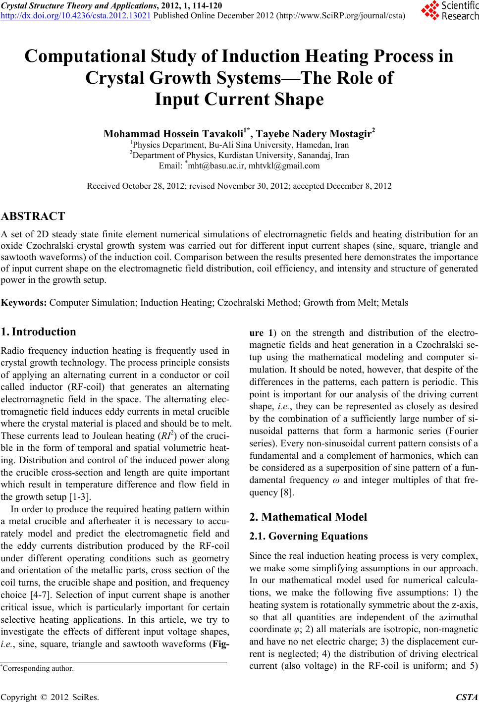
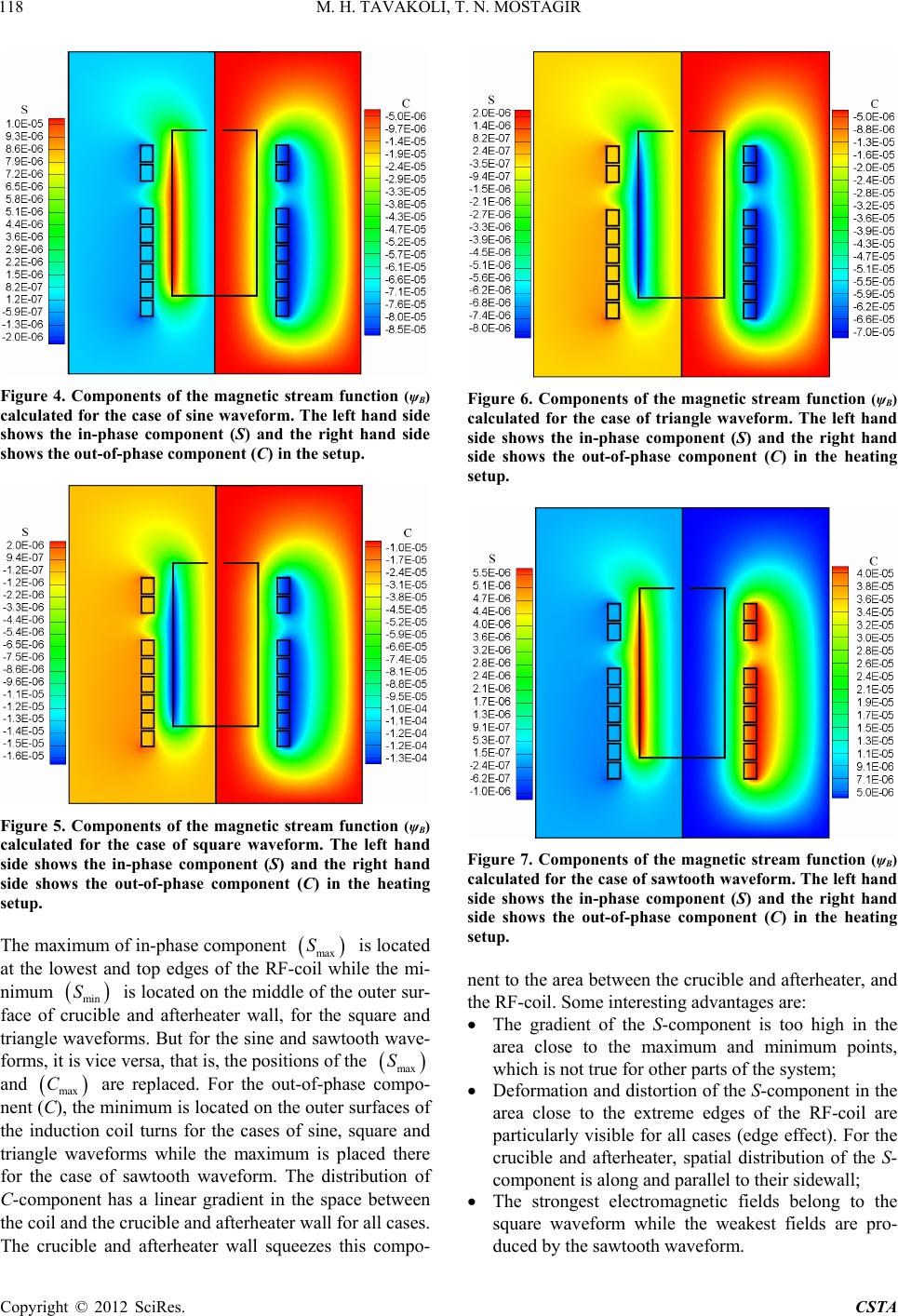
A square input current results in a high intense heating
of the crucible and afterheater while a sawtooth wave-
form leads to a low heating intensity in that part of the
system. Different amount of produced energy in the setu
is due to differences in the intensity and distribution of
the electromagnetic fields. Understanding the physics of
these n-
No. 3-4, 1989, pp. 792-826.
doi:10.1 (8
p
properties is important during designing of an i
duction system for certain crystal growth applications.
REFERENCES
[1] J. J. Derby, L. J. Atherton and P. M. Gresho, “An Integra-
ted Process Model for the Growth of Oxide Crystals by
the Czochralski Method,” Journal of Crystal Growth, Vol.
97,
016/0022-0248 9)90583-6
[ Pulli the M-
lag, Berlieidelberg, 19
/978
2] D. T. J. Hurle, “Crystalng fromelt,” Springer
Vern, H93.
doi:10.1007 -3-642-78208-4
ent[3] ein and Philip, “Transi Numerical
f Induc Heating durSublimationth of
O. Kl P. Investiga-
tion otioning Grow
Silicon Carbide Single Crystals,” Journal of Crystal Growth,
Vol. 247, No. 1-2, 2003, pp. 219-235.
doi:10.1016/S0022-0248(02)01903-6
[4] M. H. Tavakoli, F. Samavat and M. Babaiepour, “Influen
of Active Afterheater on the Induction Heating Process
ce
in
Oxide Czochralski Systems,” Crystal Research and Tech-
nology, Vol. 451. 3, No. 2, 2008, pp. 145-1
doi:10.1002/crat.200710993
[5] M. H. Tavakoli, A. Ojaghi, E. Mohammadi-Manesh and
M. Mansour, “Influence of Coil Geometry on the Induc-
tion Heating Process in Crystal Growth Systems,” Jour-
nal of Crystal Growth, Vol. 311, No
1599. doi:10.1016/j.jcrysgro.2009.01
. 6, 2009, pp. 1594-
.092
[6] M. H. Tavakoli, E. Mohammadi-Manes and A. Ojaghi, “In-
fluence of Crucible Geometry and P
tion Heating Process in Crystal G
osition on the Induc-
rowth Systems,” Jour-
nal of Crystal Growth, Vol. 311, No. 17, 2009, pp. 4281-
4288. doi:10.1016/j.jcrysgro.2009.07.013
[7] M. H. Tavakoli, H. Karbaschi, F. Samavat and E. Moham-
madi-Manesh, “Numerical Study of Induction
Melt Growth Systems—Frequency Se
Heating in
lection,” Journal of
Crystal Growth, Vol. 312, No. 21, 2010, pp. 3198-3203.
doi:10.1016/j.jcrysgro.2010.07.035
[8] G. H. Hardy and W. W. Rogosinski, “Fourier Series,” Do-
ver, 1999.
[9] M. H. Tavakoli, “Modeling of Induction Heating in Oxide
Czochralski Systems Advantages and Problems,” Crystal
Growth Design, Vol. 8, No. 2, 2007, pp. 483-488.
doi:10.1021/cg070378+
[10] S. Zinn and S. L. Semiatin, “Elements of Induction Heat-
ing,” ASM International, Cleveland, 1988.
[11] V. Rudnev, D. Loveles, R. Cook and M. Black, “Handbook
of Induction Heating,” CRC Press, New York, 2003.