Circuits and Systems
Vol.07 No.11(2016), Article ID:70639,13 pages
10.4236/cs.2016.711317
Performance Metric of Z Source CHB Multilevel Inverter FED IM for Selective Harmonic Elimination and THD Reduction
V. Maheswari1*, V. Nandagopal1, C. Kannan2
1Department of Electrical and Electronics Engineering, Sreenivasa Institute of Technology and Management Studies, Murukambattu Chittoor, India
2Department of Electrical and Electronics Engineering, Arunai Engineering College, Tiruvannamalai, India

Copyright © 2016 by authors and Scientific Research Publishing Inc.
This work is licensed under the Creative Commons Attribution International License (CC BY 4.0).
http://creativecommons.org/licenses/by/4.0/


Received: May 6, 2016; Accepted: May 20, 2016; Published: September 16, 2016
ABSTRACT
This paper focuses on a Z source cascaded multilevel inverter which is designed to minimize harmonics in the output voltage. A balanced dc-link peak voltage can be achieved. The power generation module is built by PV panels which are connected to Z-Source Cascade H-bridge inverter. Cascaded multilevel inverter can achieve the distributed maximum power point tracking to increase the system efficiency and achieve high voltage/high power grid tie without a transformer. This paper analyzes the different PWM switching scheme and the operating states of a ZSI module and comparison is made with different PWM and total harmonic distortion of various PWM schemes.
Keywords:
Z Source Inverter, Cascade H Bridge Multilevel Inverter, Photovoltaic System

1. Introduction
Alternate energy sources such as solar, fuel cell, and wind have a wide voltage change range due to the nature of these sources. Photovoltaic cell voltage varies with temperature and irradiation. Fuel cell stack voltage drops greatly with load current. And wind generator voltage varies with wind speed and control. The traditional voltage source inverter that has been the power conversion technology for these energy sources cannot cope with the wide voltage change and often requires additional voltage boost by additional dc-dc converter, which increases cost, system complexity, and power loss. The Z-source converter/inverter systems can solve this problem. This single stage power conversion technology provides a great alternative with lower cost, higher reliability, and higher efficiency. System configurations, operating principles, features and results will be presented for advanced power conditioning of alternate energy systems. For any grid connected applications we need to use inverters and converters. Especially for renewable energy sources we use energy conversions. Figure 1 shows the conventional Z- source inverter.
A number of technical papers for minimization of THD have been reported for fundamental frequency operation using the most common multilevel (ML) inverter topologies [1] . The cascaded multilevel configuration has independent dc sources that have same voltage levels. Those dc sources might be capacitors, and have experienced strong development over the past few years. This study deals with the conversion line for a grid-connected photo voltaic system. It is assumed that the PV technology used is a crystalline one, because of its large spreading on the current market [2] [3] .
Space vector modulation and carrier based modulation are proposed [4] . To reduce conventional losses transformer less MLI is proposed [5] . A single-phase multistring five-level photovoltaic (PV) inverter topology for grid-connected PV systems with a novel pulse width-modulated (PWM) control scheme is proposed [6] . Fuzzy controller for cascade MLI is adopted [7] - [9] . Comparisons have made with SVM and carrier based modulation [10] . It focused on harmonic elimination in non equal dc voltage source [11] [12] .
These devices, with their strong building integration and their development in urban zones can be subjected to severe shadows. Under these conditions, the PV field works under mismatching conditions that can lead to important power losses. Due to the climatic conditions and location, the solar panels produce different power output. Therefore while cascading PV power loss and string current exist. To minimize the string current, string current diverter should be used. The proposed system should decrease the drawbacks and keep the system reliable. This work focuses on total harmonics minimization efficient conversion. An asymmetric topology of this inverter is proposed here.

Figure 1. Conventional Z source inverter.
2. Proposed System
ZSI based Solar Power Generation System fed induction motor drive, where a unique impedance network is introduced to couple the inverter main circuit to the power source. A ZSI based Solar Power Generation System fed induction motor drive system has four major parts: a PV array-Source of DC voltage, Z-Source network containing two series inductors and two equal diagonally connected capacitors, a three-phase IGBT/Diode based inverter bridge and a three-phase induction motor drive. For feeding the required DC voltage to the Z-source Network, a PV array is used to generate the DC voltage with proper series and parallel combination of PV cells. Reverse current flow can be prevented by connecting a diode in series with the load circuit. The L1, L2, C1 and C2 are forming the Z-Source network. The boost function of the generated DC voltage is achieved by this Z-source network. The ZSI Bridge can boost the DC capacitors (C1 and C2) voltage to any value that is the above the average DC value of the PV array. The output voltage is always obtainable regardless of the line voltage with the help of Z-source Bridge. Comparing the Z-source inverters with the traditional inverters, a shoot through state that the upper and lower switches of any one phase leg are shorten and this is the added state besides the zero state and active state. Figure 2 shows the proposed Z source cascade H bridge inverter.
3. PWM Strategies
3.1. Phase Disposition (PD) PWM
In this method all the carriers are have the same frequency, same amplitude and same phase. All carriers selected above and below the zero reference are in same phase and amplitude of each carrier is chosen as 1. Figure 3 shows the carrier arrangement for PDPWM strategy with sine reference and Figure 4 shows the carrier arrangement for PDPWM strategy with trapezoidal reference. Since all carriers are in same phase it is named as Phase Disposition PWM PDPWM). Amplitude Modulation for this strategy is defined as:

Figure 2. Proposed Z source cascade H bridge.

Figure 3. Carrier arrangement for PDPWM strategy with sine reference.

Figure 4. Carrier arrangement for PDPWM strategy with trapezoidal reference.

where n is the number of carriers.
3.2. Phase Opposition and Disposition (POD) PWM
This technique employs a number of carriers (m − 1) which are all in phase above and below the zero reference. For example in 5-level converters all the four carrier waves are phase shifted by 180 degrees between the ones above and below zero reference. The reference signal is compared with all four carrier waves thereby gate pulses are generated and are associated to each switching devices. The carrier arrangement for this scheme with respect to the sine and trapezoidal reference wave is shown in the following Figure 5 and Figure 6.
3.3. Alternative Phase Opposition and Disposition (APOD) PWM
In this strategy, carries are seem to be invert their phase in turns from previous one so it is named as Alternate Phase Opposition Disposition PWM (APODPWM) strategy. Carrier set placed above the zero reference with Amplitude. The carrier arrangement for this scheme with respect to the sine and trapezoidal reference wave is shown in the following Figure 7 and Figure 8.

Figure 5. Carrier arrangement for PODPWM strategy with sine reference.
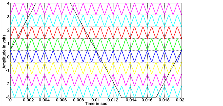
Figure 6. Carrier arrangement for PODPWM strategy with trapezoidal reference.

Figure 7. Carrier arrangement for APODPWM strategy with sine reference.

Figure 8. Carrier arrangement for APODPWM strategy with trapezoidal reference.
4. Simulation Results
The simulation results of various PWM schemes of corresponding ZS cascaded H bridge multilevel inverter fed with motor load is shown in figures below. The total harmonic distortion obtained for sinusoidal PDPWM scheme is dissipated in Figure 9, which the fundamental frequency 50 Hz, the fundamental voltage obtained 67.9 V and the total harmonic distortion is 14.52%.
Figure 10 shows the motor speed and torque obtained for nine level inverter for sinusoidal PDPWM strategy in which the motor attains the maximum speed in three seconds.
The total harmonic distortion obtained for Trapezoidal PDPWM scheme is dissipated in Figure 11, which the fundamental frequency 50 Hz, the fundamental voltage

Figure 9. FFT Plot analysis of sinusoidal PDPWM scheme.

Figure 10. Motor speed and torque of Z source integrated nine level inverter for sinusoidal PDPWM strategy.

Figure 11. FFT plot analysis of trapezoidal PDPWM scheme.
obtained 74.96 V and the total harmonic distortion is 12.38%.
Figure 12 shows the motor speed and torque obtained for nine level inverter for trapezoidal PDPWM strategy in which the motor attains the maximum speed in two and half seconds.
The total harmonic distortion obtained for sinusoidal PODPWM scheme is dissipated in Figure 13, which the fundamental frequency 50 Hz, the fundamental voltage obtained 67.86 V and the total harmonic distortion is 16.98%.
It also shows the THD analysis of PDPOD and APOD sinusoidal PWM strategies.
Figure 14 shows the motor speed and torque obtained for nine level inverter for sinusoidal POD PWM strategy in which the motor attains the maximum speed in two and half seconds.
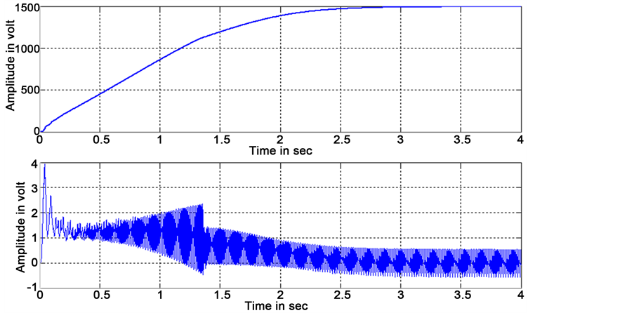
Figure 12. Motor speed and torque of Z-source integrated nine level inverter for trapezoidal PDPWM strategy.

Figure 13. FFT plot analysis of sinusoidal POD PWM scheme.

Figure 14. Motor speed and torque of Z-source integrated nine level inverter for sinusoidal PODPWM strategy.
The total harmonic distortion obtained for Trapezoidal PODPWM scheme is dissipated in Figure 15, which the fundamental frequency 50 Hz, the fundamental voltage obtained 67.86 V and the total harmonic distortion is 11.61%.
Figure 16 shows the motor speed and torque obtained for nine level inverter for trapezoidal POD PWM strategy in which the motor attains the maximum speed in two and half seconds.
The total harmonic distortion obtained for sinusoidal APODPWM scheme is dissipated in Figure 17, which the fundamental frequency 50 Hz, the fundamental voltage obtained 67.95 V and the total harmonic distortion is 14.66%.
Figure 18 shows the motor speed and torque obtained for nine level inverter for sinusoidal APOD PWM strategy in which the motor attains the maximum speed in three seconds.
The total harmonic distortion obtained for trapezoidal APODPWM scheme is dissipated in Figure 19, which the fundamental frequency 50 Hz, the fundamental voltage obtained 67.95 V and the total harmonic distortion is 14.66%.
Figure 20 shows the motor speed and torque obtained for nine level inverter for trapezoidal APOD PWM strategy in which the motor attains the maximum speed in three seconds.
The output voltage of Z source integrated nine level inverter with motor load is show in Figure 21. The output wave form obtained 67 V.
Table 1 comparison of THD for different PWM strategies with sine reference.
Table 2 comparison of THD for different PWM strategies with trapezoidal reference.
The comparison for three different PWM schemes is charted below with the total harmonic distortion tabulated in graph which is shown in Figure 22.

Figure 15. FFT plot analysis of trapezoidal PODPWM scheme.
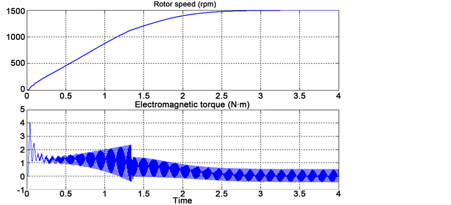
Figure 16. Motor speed and torque of Z-source integrated nine level inverter for trapezoidal PODPWM strategy.

Figure 17. FFT plot analysis of sinusoidal APODPWM scheme.

Figure 18. Motor speed and torque of Z-source integrated nine level inverter for sinusoidal APODPWM strategy.

Figure 19. FFT plot analysis of trapezoidal APODPWM scheme.
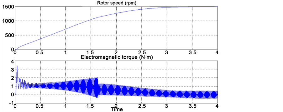
Figure 20. Motor speed and torque of Z-source integrated nine level inverter for trapezoidal APODPWM strategy.

Figure 21. Output voltage of Z-source integrated nine level inverter with motor load.

Figure 22. THD for different PWM strategies with sine reference and trapezoidal reference.

Table 1. %THD for different PWM strategies with sine reference.
Table 2. %THD for different PWM strategies with trapezoidal reference.
5. Conclusion
A cascaded multilevel inverter fed with ZSI has been proposed to overcome the shortcoming of the existing solutions in PV power system. The proposed circuit has fewer power semiconductors compared with the existing three-phase seven-level cascaded multilevel inverter. There are only eight power switches in the proposed nine-level multilevel inverter configuration. The passive component ratings are reduced to eliminate harmonics which exists in ZSI module. The balanced dc-link peak voltage is achieved by the control schemes. Simulations with different PWM techniques were carried out to verify the THD of proposed model. It is obtained that the trapezoidal PODPWM strategy has better %THD.
Cite this paper
Maheswari, V., Nan- dagopal, V. and Kannan, C. (2016) Performance Metric of Z Source CHB Multilevel Inverter FED IM for Selective Harmonic Eli- mination and THD Reduction. Circuits and Systems, 7, 3794-3806. http://dx.doi.org/10.4236/cs.2016.711317
References
- 1. Pilehvar, M.S., Mardaneh, M. and Rajaei, A. (2015) Formulation of Phase Voltage and Calculation of Its Total Harmonic Distortion in Multilevel Z-Source Inverter. IET Power Electronics, 8, 1509-1518.
http://dx.doi.org/10.1049/iet-pel.2014.0512 - 2. Lu, Z.-G., Zhao, L.-L., Zhu, W.-P. and Wu, C.-J. (2013) Research on Cascaded Three- Phase-Bridge Multilevel Converter Based on CPS-PWM. IET Power Electronics, 6, 1088- 1099.
http://dx.doi.org/10.1049/iet-pel.2012.0510 - 3. Du, Z., Tolbert, L.M., Ozpineci, B. and Chiasson, J.N. (2009) Fundamental Frequency Switching Strategies of a Seven-Level Hybrid Cascaded H-Bridge Multilevel Inverter. IEEE Transactions on Power Electronics, 28, 25-33.
http://dx.doi.org/10.1109/TPEL.2008.2006678 - 4. Effah, F.B., Wheeler, P., Clare, J. and Watson, A. (2012) Space-Vector-Modulated Three- Level Inverters with a Single Z-Source Network. IEEE Transactions on Power Electronics, 28, 2806-2815.
http://dx.doi.org/10.1109/TPEL.2012.2219627 - 5. Liao, Y.-H. and Lai, C.-M. (2011) Newly-Constructed Simplified Single-Phase Multistring Multilevel Inverter Topology for Distributed Energy Resources. IEEE Transactions on Power Electronics, 26, 2386-2392.
http://dx.doi.org/10.1109/TPEL.2011.2157526 - 6. Rahim, N.A. and Selvaraj, J. (2010) Multistring Five-Level Inverter with Novel PWM Control Scheme for PV Application. IEEE Transactions on Industrial Electronics, 57, 2111- 2123.
http://dx.doi.org/10.1109/TIE.2009.2034683 - 7. Cecati, C., Ciancetta, F. and Siano, P. (2010) A Multilevel Inverter for Photovoltaic Systems with Fuzzy Logic Control. IEEE Transactions on Industrial Electronics, 57, 4115-4125.
http://dx.doi.org/10.1109/TIE.2010.2044119 - 8. Bayindir, R., Colak, I., Kabalci, E. and Irmak, E. (2009) The Fuzzy Logic Control of a Multilevel Converter in a Variable Speed Wind Turbine. International Conference on Machine Learning and Applications, 787-790.
- 9. Corzine, K.A., Wielebski, M.W., Peng, F.Z. and Wang, J. (2004) Control of Cascaded Multilevel Inverters. IEEE Transactions on Power Electronics, 19, 732-738.
http://dx.doi.org/10.1109/TPEL.2004.826495 - 10. Yao, W., Hu, H. and Lu, Z. (2008) Comparisons of Space-Vector Modulation and Carrier- Based Modulation of Multilevel Inverter. IEEE Transactions on Power Electronics, 23, 45- 51.
http://dx.doi.org/10.1109/TPEL.2007.911865 - 11. Tolbert, L.M., Chiasson, J.N., Du, Z. and McKenzie, K.J. (2005) Elimination of Harmonics in a Multilevel Converter with Nonequal DC Sources. IEEE Transactions on Industry Applications, 41, 75-82.
http://dx.doi.org/10.1109/TIA.2004.841162 - 12. Chiasson, J.N., Tolbert, L.M., McKenzie, K.J. and Du, Z. (2005) Elimination of Harmonics in a Multilevel Converter Using the Theory of Symmetric Polynomials and Resultants. IEEE Transactions on Control Systems Technology, 13, 216-223.
http://dx.doi.org/10.1109/TCST.2004.839556