Paper Menu >>
Journal Menu >>
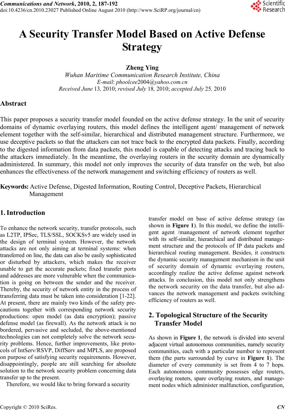 Communications and Network, 2010, 2, 187-192 doi:10.4236/cn.2010.23027 Published Online August 2010 (http://www.SciRP.org/journal/cn) Copyright © 2010 SciRes. CN A Security Transfer Model Based on Active Defense Strategy Zheng Ying Wuhan Maritime Communication Research Institute, China E-mail: phoolcee2004@yahoo.com.cn Received June 13, 2010; revised July 18, 2010; accepted July 25, 2010 Abstract This paper proposes a security transfer model founded on the active defense strategy. In the unit of security domains of dynamic overlaying routers, this model defines the intelligent agent/ management of network element together with the self-similar, hierarchical and distributed management structure. Furthermore, we use deceptive packets so that the attackers can not trace back to the encrypted data packets. Finally, according to the digested information from data packets, this model is capable of detecting attacks and tracing back to the attackers immediately. In the meantime, the overlaying routers in the security domain are dynamically administered. In summary, this model not only improves the security of data transfer on the web, but also enhances the effectiveness of the network management and switching efficiency of routers as well. Keywords: Active Defense, Digested Information, Routing Control, Deceptive Packets, Hierarchical Management 1. Introduction To enhance the network security, transfer protocols, such as L2TP, IPSec, TLS/SSL, SOCKSv5 are widely used in the design of terminal system. However, the network attacks are not only aiming at terminal systems: when transferred on line, the data can also be easily sophisticated or disturbed by attackers, which makes the receiver unable to get the accurate packets; fixed transfer ports and addresses are more vulnerable when the communica- tion is going on between the sender and the receiver. Thereby, the security of network entity in the process of transferring data must be taken into consideration [1-22]. At present, there are mainly two kinds of the safety pre- cautions together with corresponding network security productions: open model (as data encryption); passive defense model (as firewall). As the network attack is no bordered, pervasive and secluded, the above-mentioned technologies can not completely solve the network secu- rity problems. Hence, further improvements, like proto- cols of IntServ/RSVP, DiffServ and MPLS, are proposed on purpose of satisfying security requirements. However, disappointingly, people are still searching for absolute solution to the network security problem concerning data transfer up to the present. Therefore, we would like to bring forward a security transfer model on base of active defense strategy (as shown in Figure 1). In this model, we define the intelli- gent agent /management of network element together with its self-similar, hierarchical and distributed manage- ment structure and the protocols of IP data packets and hierarchical routing management. Besides, it constructs the dynamic security management mechanism in the unit of security domain of dynamic overlaying routers, accordingly realize the active defense against network attacks. In conclusion, this model not only strengthens the network security on the data transfer, but also ad- vances the network management and packets switching efficiency of routers as well. 2. Topological Structure of the Security Transfer Model As shown in Figure 1, the network is divided into several adjacent virtual autonomous communities, namely security communities, each with a particular number to represent them (the parts surrounded by curve in Figure 1). The diameter of every community is set from 4 to 7 hops. Each autonomous community possesses edge routers, overlaying routers, spare overlaying routers, and manage- ment nodes which administer malfunction, configuration, 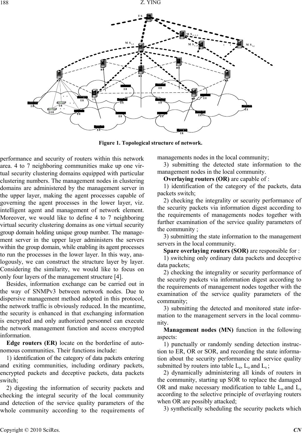 Z. YING 188 ER ER ER ER ER ER ER ER ER ER ER ER ER ER OR . SOR . .. MN MN MN MN MN MN MN . . MS i,1 MS i ,2MS i,j . . . MS i+ 1 ,1 TS Figure 1. Topological structure of network. performance and security of routers within this network area. 4 to 7 neighboring communities make up one vir- tual security clustering domains equipped with particular clustering numbers. The management nodes in clustering domains are administered by the management server in the upper layer, making the agent processes capable of governing the agent processes in the lower layer, viz. intelligent agent and management of network element. Moreover, we would like to define 4 to 7 neighboring virtual security clustering domains as one virtual security group domain holding unique group number. The manage- ment server in the upper layer administers the servers within the group domain, while enabling its agent processes to run the processes in the lower layer. In this way, ana- logously, we can construct the structure layer by layer. Considering the similarity, we would like to focus on only four layers of the management structure [4]. Besides, information exchange can be carried out in the way of SNMPv3 between network nodes. Due to dispersive management method adopted in this protocol, the network traffic is obviously reduced. In the meantime, the security is enhanced in that exchanging information is encrypted and only authorized personnel can execute the network management function and access encrypted information. Edge routers (ER) locate on the borderline of auto- nomous communities. Their functions include: 1) identification of the category of data packets entering and exiting communities, including ordinary packets, encrypted packets and deceptive packets, data packets switch; 2) digesting the information of security packets and checking the integral security of the local community and detection of the service quality parameters of the whole community according to the requirements of managements nodes in the local community; 3) submitting the detected state information to the management nodes in the local community. Overlaying routers (OR) are capable of : 1) identification of the category of the packets, data packets switch; 2) checking the integrality or security performance of the security packets via information digest according to the requirements of managements nodes together with further examination of the service quality parameters of the community ; 3) submitting the state information to the management servers in the local community. Spare overlaying routers (SOR) are responsible for : 1) switching only ordinary data packets and deceptive data packets; 2) checking the integrality or security performance of the security packets via information digest according to the requirements of management nodes together with the examination of the service quality parameters of the community; 3) submitting the detected and monitored state infor- mation to the management servers in the local commu- nity. Management nodes (MN) function in the following aspects: 1) punctually or randomly sending detection instruc- tion to ER, OR or SOR, and recording the state informa- tion about the security performance and service quality submitted by routers into table Le, Lo and Ls ; 2) dynamically administering all kinds of routers in the community, starting up SOR to replace the damaged OR and make necessary modification to table Lo and Ls according to the selective principle of overlaying routers when OR are possibly attacked; 3) synthetically scheduling the security packets which C opyright © 2010 SciRes. CN 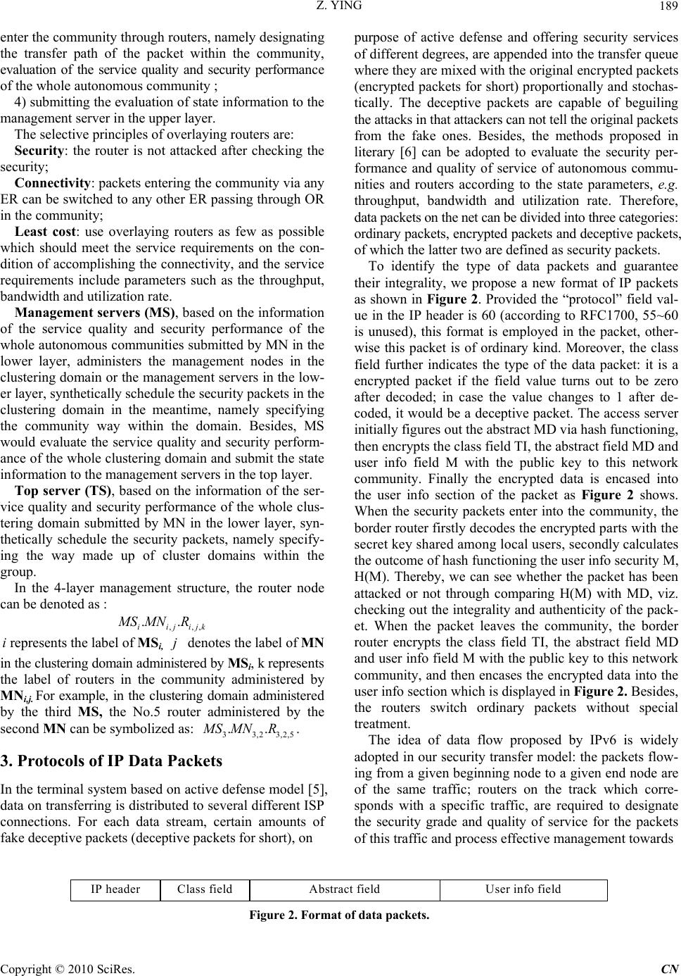 Z. YING189 k enter the community through routers, namely designating the transfer path of the packet within the community, evaluation of the service quality and security performance of the whole autonomous community ; 4) submitting the evaluation of state information to the management server in the upper layer. The selective principles of overlaying routers are: Security: the router is not attacked after checking the security; Connectivity: packets entering the community via any ER can be switched to any other ER passing through OR in the community; Least cost: use overlaying routers as few as possible which should meet the service requirements on the con- dition of accomplishing the connectivity, and the service requirements include parameters such as the throughput, bandwidth and utilization rate. Management servers (MS), based on the information of the service quality and security performance of the whole autonomous communities submitted by MN in the lower layer, administers the management nodes in the clustering domain or the management servers in the low- er layer, synthetically schedule the security packets in the clustering domain in the meantime, namely specifying the community way within the domain. Besides, MS would evaluate the service quality and security perform- ance of the whole clustering domain and submit the state information to the management servers in the top layer. Top server (TS), based on the information of the ser- vice quality and security performance of the whole clus- tering domain submitted by MN in the lower layer, syn- thetically schedule the security packets, namely specify- ing the way made up of cluster domains within the group. In the 4-layer management structure, the router node can be denoted as : ,,, .. iijij M SMN R irepresents the label of MSi, denotes the label of MN in the clustering domain administered by MSi, k represents the label of routers in the community administered by MNi,j. For example, in the clustering domain administered by the third MS, the No.5 router administered by the second MN can be symbolized as: . j 33,23,2 ..MS MNR,5 3. Protocols of IP Data Packets In the terminal system based on active defense model [5], data on transferring is distributed to several different ISP connections. For each data stream, certain amounts of fake deceptive packets (deceptive packets for short), on purpose of active defense and offering security services of different degrees, are appended into the transfer queue where they are mixed with the original encrypted packets (encrypted packets for short) proportionally and stochas- tically. The deceptive packets are capable of beguiling the attacks in that attackers can not tell the original packets from the fake ones. Besides, the methods proposed in literary [6] can be adopted to evaluate the security per- formance and quality of service of autonomous commu- nities and routers according to the state parameters, e.g. throughput, bandwidth and utilization rate. Therefore, data packets on the net can be divided into three categories: ordinary packets, encrypted packets and deceptive packets, of which the latter two are defined as security packets. To identify the type of data packets and guarantee their integrality, we propose a new format of IP packets as shown in Figure 2. Provided the “protocol” field val- ue in the IP header is 60 (according to RFC1700, 55~60 is unused), this format is employed in the packet, other- wise this packet is of ordinary kind. Moreover, the class field further indicates the type of the data packet: it is a encrypted packet if the field value turns out to be zero after decoded; in case the value changes to 1 after de- coded, it would be a deceptive packet. The access server initially figures out the abstract MD via hash functioning, then encrypts the class field TI, the abstract field MD and user info field M with the public key to this network community. Finally the encrypted data is encased into the user info section of the packet as Figure 2 shows. When the security packets enter into the community, the border router firstly decodes the encrypted parts with the secret key shared among local users, secondly calculates the outcome of hash functioning the user info security M, H(M). Thereby, we can see whether the packet has been attacked or not through comparing H(M) with MD, viz. checking out the integrality and authenticity of the pack- et. When the packet leaves the community, the border router encrypts the class field TI, the abstract field MD and user info field M with the public key to this network community, and then encases the encrypted data into the user info section which is displayed in Figure 2. Besides, the routers switch ordinary packets without special treatment. The idea of data flow proposed by IPv6 is widely adopted in our security transfer model: the packets flow- ing from a given beginning node to a given end node are of the same traffic; routers on the track which corre- sponds with a specific traffic, are required to designate the security grade and quality of service for the packets of this traffic and process effective management towards Class fieldAbstract fieldIP headerUser info field Figure 2. Format of data packets. Copyright © 2010 SciRes. CN 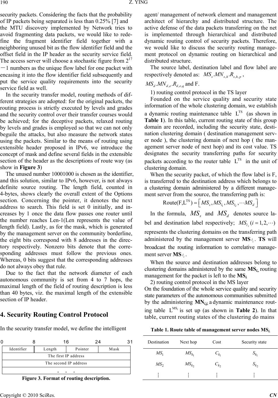 Z. YING 190 security packets. Considering the facts that the probability of IP packets being separated is less than 0.25% [7] and the MTU discovery implemented by Network tries to avoid fragmenting data packets, we would like to rede- fine the fragment identifier field together with a neighboring unused bit as the flow identifier field and the offset field in the IP header as the security service field. The access server will choose a stochastic figure from 217 -1 numbers as the unique flow label for one packet with encasing it into the flow identifier field subsequently and put the service quality requirements into the security service field as well. In the security transfer model, routing methods of dif- ferent strategies are adopted: for the original packets, the routing process is strictly executed by levels and grades and the security control over their transfer courses would be achieved; for the deceptive packets, relaxed routing by levels and grades is employed so that we can not only beguile the attacks, but also measure the network states using the packets. Similar to the means of routing using extensible header proposed in IPv6, we introduce the concept of mask and define several fields in the extensible section of the header as the descriptions of route way (as show in Figure 3) The unused number 10001000 is chosen as the identifier, and this solution, similar to IPv6, however, is not always definite source routing. The length field, counted in 4-bytes, shows clearly the overall extent of the Options section. Concerning the pointer, it denotes the next address to search. This field is set 0 initially, and in- creases by 1 once the data flow passes one router until the number reaches Len-1(Len represents the value of length field). Lastly, as for the mask, which is generated by the management server on the community borderline, the eight bits correspond with 8 addresses in the direc- tory respectively. Nonzero bits denote that the corre- sponding addresses must follow the previous ones. Whereas, 0 bits suggest that the corresponding addresses do not always obey that rule. Due to the fact that the network diameter of each autonomous community is set from 4 to 7 hops, the maximal length of the field of routing description is less than 40 bytes, viz. the maximal length of the extensible section of IP header. 4. Security Routing Control Protocol In the security transfer model, we define the intelligent 0 Identifier Length Pointer Mask The first IP address The second IP address ... 816 24 agent/ management of network element and management architect of hierarchy and distributed structure. The active defense of the data packets transferring on the net is implemented through hierarchical and distributed dynamic routing control of security packets. Therefore, we would like to discuss the security routing manage- ment protocol on dynamic routing on hierarchical and distributed structure. The source label, destination label and flow label are respectively denoted as: ,,, .. s sh shp MS MNR, ,,, .. ddede MS MNRq and F. 1) routing control protocol in the TS layer Founded on the service quality and security state information of the whole clustering domain, we establish a dynamic routing maintenance table (as shown in Table 1). In this table, current routing state of this group domain are recorded, including the security state, desti- nation clustering domain ( destination management serv- er node ), the clustering domain of next hop ( the man- agement server node of next hop) and its cost value. TS designates the security transferring paths for security packets according to the router table in the unit of clustering domain. TS L TS L When the security packet, of which the flow label is F, is transferred to the destination address which belongs to a clustering domain administered by a different manage- ment server from the source, the transferring path is: 12 TS Route(F,L ),,, sl ld M SMS MSMS In the formula, s M S and d M S denotes source la- bel and destination label respectively; (1,2,) i l MS i i l represents the clustering domains on the transferring path administered by the management server MS. TS will broadcast the routing information to correlative manage- ment server MS . i l When the source and destination addresses belong to clustering domains administered by the same MSi,, routing management for the packet is left to the MSi. 2) routing control protocol in the MS layer On the foundation of the whole service quality and security state parameters of the autonomous communities submitted by the administering MNi,j, a dynamic maintenance rout- ing table is set up (as shown in Table 2). In that table, current routing states of the clustering do mains MS Li Table 1. Route table of management server nodes MSi. 31 Figure 3. Format of routing description. Destination Next hop Cost Security state 1 M S 1 k M S 1 k C 1 k S 2 M S 2 k M S 2 k C 2 k S ┆ ┆ ┆ ┆ C opyright © 2010 SciRes. CN 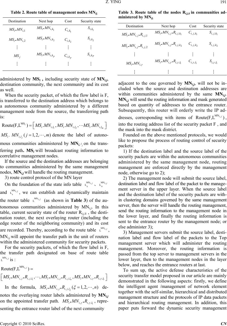 Z. YING191 Table 2. Route table of management nodes MNij. Destination Next hop Cost Security state ,1 . ii M SMN 1 , . iik MS MN 1 ,ik C 1 ,ik S ,2 . ii M SMN 2 , . iik MS MN 2 ,ik C 2 ,ik S ┆ ┆ ┆ ┆ j M S , . p iik MS MN , p ik C , P ik S ┆ ┆ ┆ ┆ administered by MSi , including security state of MNi,j, destination community, the next community and its cost as well. When the security packet, of which the flow label is F, is transferred to the destination address which belongs to a autonomous community administered by a different management node from the source, the transferring path is: 12 MS ,, Route(F,L ).,.,. i m iil iiliil MS MNMS MNMS MN , . i M S,(1,2,, j il ) M Nj mdenote the label of autono- mous communities administered by MNi, j lon the trans- ferring path. MSi will broadcast routing information to correlative management nodes. If the source and the destination addresses are belonging to communities administered by the same management nodes, MNi,j will handle the routing management. 3) route control protocol of the MN layer On the foundation of the state info table 、 and , we can establish and dynamically maintain the router table (as shown in Table 3) of the au- tonomous communities administered by MNi,j. In this table, current security state of the router Ri,j,k , the desti- nation router, the next overlaying router (including the edge router of the neighboring community) and its cost are recorded. Thereby, according to the route table , MNi,j will appoint the transfer path in the unit of routers within the administered community for security packets. MN , e Lij MN, o Lij MN , Lij MN , s Lij MN , Lij For the security packets, of which the flow label is F, the transfer path designated on base of route table is : MN , Lij , 1 MN ,,,,,, ,,, Route(F,L ) ,, , .... .. ij n i ijijli ijijliiil MS MNRMS MNRMS MNR 1 ) In the formula, ,,, (1,2,,.. iijijl M SMN Rn de- notes the overlaying router labels administered by MNi,j on the appointed transfer path. 1 ,,, .. iiil MS MNR , repre- senting the entrance router label of the next community Table 3. Route table of the nodes Ri,j,k in communities ad- ministered by MNij. Destination Next hop Cost Security state ,,, .. iijij MS MNR11 ,,, .. iijijk MS MNR 1 ,,ijk C 1 ,,ijk S ,,, .. iijij MS MNR22 ,,, .. iijijk MS MNR 2 ,,ijk C 2 ,,ijk S ┆ ┆ ┆ ┆ , . ii M SMN 1 ,,, .. iiil MS MNR 1 ,,il C 1 ,,il S ┆ ┆ ┆ ┆ adjacent to the one governed by MNi,j, will not be in- cluded when the source and destination addresses are within communities administered by the same MNi,j. MNi,j will send the routing information and mask generated based on quantity of addresses to the entrance router. Subsequently, this router will orderly write the IP ad- dresses, corresponding with items of , into the routing address list of the security packet F , and the mask into the mask district. , MN Route(F,L ) ij Founded on the above mentioned protocols, we would like to propose the process of routing control of security packets: 1) If the destination label and the source label of the security packets are within the autonomous communities administered by the same management node, routing management are enforced directly by the management node, otherwise go to 2); 2) The management node will submit the source label, destination label and flow label of the packet to the manage- ment server in the upper layer. When the source label and the destination label of the security packets are with- in clustering domains governed by the same management server, then the server will handle the routing management, send the routing information to the management node in the lower layer, and finally the routing information is sent to the entrance router by the management node; or else administer 3); 3) Management servers submit the source label, desti- nation label and flow label of the packets to the Top management server which will administer the routing management. Moreover, the routing information is passed from the top server to management servers in the lower layer, then to the management nodes in the layer below, and reaches the entrance routers at last. To sum up, the active defense characteristics of the security transfer model proposed in our article are mainly demonstrated in the following aspects: firstly, we define the intelligent agent /management of network element together with the self-similar, hierarchical and distributed management structure and the protocols of IP data packets and hierarchical routing management. In addition, this paper puts forward the dynamic security management Copyright © 2010 SciRes. CN 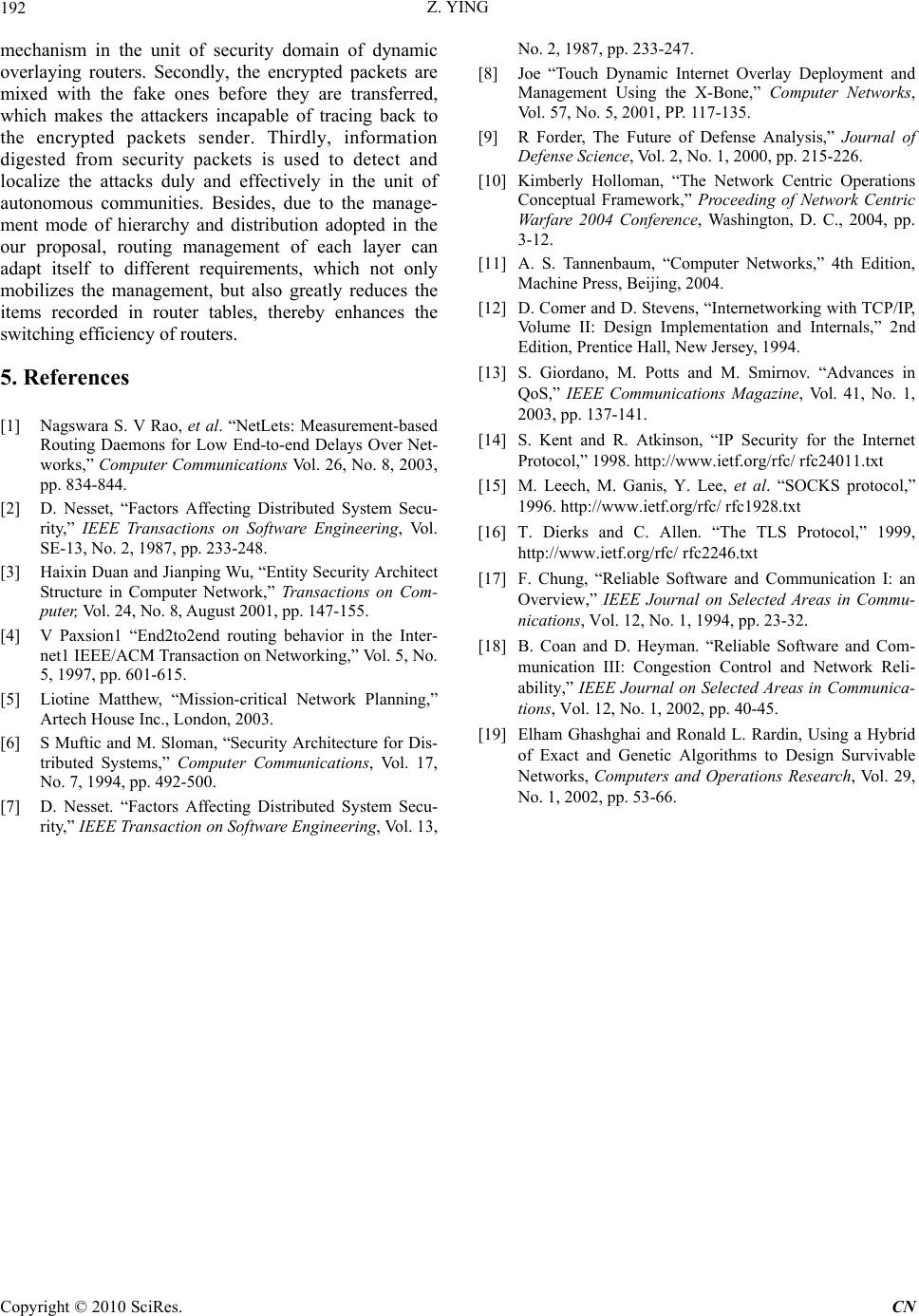 Z. YING Copyright © 2010 SciRes. CN 192 mechanism in the unit of security domain of dynamic overlaying routers. Secondly, the encrypted packets are mixed with the fake ones before they are transferred, which makes the attackers incapable of tracing back to the encrypted packets sender. Thirdly, information digested from security packets is used to detect and localize the attacks duly and effectively in the unit of autonomous communities. Besides, due to the manage- ment mode of hierarchy and distribution adopted in the our proposal, routing management of each layer can adapt itself to different requirements, which not only mobilizes the management, but also greatly reduces the items recorded in router tables, thereby enhances the switching efficiency of routers. 5. References [1] Nagswara S. V Rao, et al. “NetLets: Measurement-based Routing Daemons for Low End-to-end Delays Over Net- works,” Computer Communications Vol. 26, No. 8, 2003, pp. 834-844. [2] D. Nesset, “Factors Affecting Distributed System Secu- rity,” IEEE Transactions on Software Engineering, Vol. SE-13, No. 2, 1987, pp. 233-248. [3] Haixin Duan and Jianping Wu, “Entity Security Architect Structure in Computer Network,” Transactions on Com- puter, Vol. 24, No. 8, August 2001, pp. 147-155. [4] V Paxsion1 “End2to2end routing behavior in the Inter- net1 IEEE/ACM Transaction on Networking,” Vol. 5, No. 5, 1997, pp. 601-615. [5] Liotine Matthew, “Mission-critical Network Planning,” Artech House Inc., London, 2003. [6] S Muftic and M. Sloman, “Security Architecture for Dis- tributed Systems,” Computer Communications, Vol. 17, No. 7, 1994, pp. 492-500. [7] D. Nesset. “Factors Affecting Distributed System Secu- rity,” IEEE Transaction on Software Engineering, Vol. 13, No. 2, 1987, pp. 233-247. [8] Joe “Touch Dynamic Internet Overlay Deployment and Management Using the X-Bone,” Computer Networks, Vol. 57, No. 5, 2001, PP. 117-135. [9] R Forder, The Future of Defense Analysis,” Journal of Defense Science, Vol. 2, No. 1, 2000, pp. 215-226. [10] Kimberly Holloman, “The Network Centric Operations Conceptual Framework,” Proceeding of Network Centric Warfare 2004 Conference, Washington, D. C., 2004, pp. 3-12. [11] A. S. Tannenbaum, “Computer Networks,” 4th Edition, Machine Press, Beijing, 2004. [12] D. Comer and D. Stevens, “Internetworking with TCP/IP, Volume II: Design Implementation and Internals,” 2nd Edition, Prentice Hall, New Jersey, 1994. [13] S. Giordano, M. Potts and M. Smirnov. “Advances in QoS,” IEEE Communications Magazine, Vol. 41, No. 1, 2003, pp. 137-141. [14] S. Kent and R. Atkinson, “IP Security for the Internet Protocol,” 1998. http://www.ietf.org/rfc/ rfc24011.txt [15] M. Leech, M. Ganis, Y. Lee, et al. “SOCKS protocol,” 1996. http://www.ietf.org/rfc/ rfc1928.txt [16] T. Dierks and C. Allen. “The TLS Protocol,” 1999, http://www.ietf.org/rfc/ rfc2246.txt [17] F. Chung, “Reliable Software and Communication I: an Overview,” IEEE Journal on Selected Areas in Commu- nications, Vol. 12, No. 1, 1994, pp. 23-32. [18] B. Coan and D. Heyman. “Reliable Software and Com- munication III: Congestion Control and Network Reli- ability,” IEEE Journal on Selected Areas in Communica- tions, Vol. 12, No. 1, 2002, pp. 40-45. [19] Elham Ghashghai and Ronald L. Rardin, Using a Hybrid of Exact and Genetic Algorithms to Design Survivable Networks, Computers and Operations Research, Vol. 29, No. 1, 2002, pp. 53-66. |