Paper Menu >>
Journal Menu >>
 Communications and Network, 2010, 2, 166-182 doi:10.4236/cn.2010.23025 Published Online August 2010 (http://www.SciRP.org/journal/cn) Copyright © 2010 SciRes. CN Comparison of 4 Multi-User Passive Network Topologies for 3 Different Quantum Key Distribution Fabio Garzia, Roberto Cusani INFOCOM Department, SAPIENZA – Universi t y of Rome , Rome, Italy E-mail: fabio.garzia@uniroma1.it Received March 30, 2010; revised May 7, 2010; accepted J une 1, 2010 Abstract The purpose of this paper is to compare the performance of four passive optical network topologies in im- plementing multi-user quantum key distribution, using 3 protocols proposed by quantum cryptography (B92, EPR, and SSP). The considered networks are the passive-star network, the optical-ring network based on the Signac interferometer, the wavelength-routed network, and the wavelength-addressed bus network. The quantum bit-error rate and sifted key rate for each of these topologies are analysed to determine their suit- ability for providing quantum key distribution-service to networks of various sizes. The efficiency of the three considered protocols is also determined. Keywords: Quantum Cryptography, Quantum Key Distribution 1. Introduction The quantum cryptography term repres ents the s et of the techniques which allow two entities, Alice and Bob, to exchange reserved information by means of a quantum channel. A qu antum ch anne l is an op tic a l channel gover ned by the quantum mechanics. The job in cryptographic field of the quantum mechanics allows results impossible to be obtained with the only mathematics. More precisely, talking about quantum key distribution (QKD) is oppor- tune: the quantum channel is used to transmit a sequence of bits, well known only to Alice and Bob and then able to constitute the secret key of a cryptographic system. Therefore the next communications which are ciphered with such key can be made on a conventional channel (not quantum). Quantum key distribution is a method for securely distributing one-time-use encryption keys that are used for secure communications. These quantum systems are based on the theorem of Heisenberg [1], according to which the measurement of a quantum sys- tem generally perturbs it and gives an incomplete piece of information on his state preceding the measurement, and on the quantum no-cloning theorem [2], which for- bids the perfect copying of two non-orthogonal quantum states. Therefore the quantum nature of a channel makes sure that any interception is noticed. Hence an eavesdropper, Eve, cannot get any information about the communica- tion without i ntroducing pertur bati ons whic h would reveal her presence. To share a secret key, Alice and Bob must follow a protocol (BB84, B92, EPR, SSP). Once developed the procedure requested by the protocol, if any eavesdropper were not noticed, Alice and Bob share a secret key, which exchanged themselves without having to turn to a third reliable part and initially sharing no information, except that the one necessary to authenticate their com- munications part. The frequency used by Alice and Bob to share the sifted secret key is denominated sifted key rate (RSIFT). To reveal the presence of an eavesdropper, Eve, Alice and Bob monitor the quantum bit error rate (QBER). If the QBER exceeds a certain threshold the made communication is just considered as not safe and therefore the secret key is discarded. The security threshold depends on the used protocol. The QBER and the RSIFT are considered the fundamental parameters to evaluate the performances of a quantum channel. This analysis has already been done for BB84 protocol [3]. The purpose of this paper is to extend the mentioned analysis to other three common protocols that are B92, EPR and SSP. The remainder of this paper is organized as follows. Section II provides a review of 3 protocols used in addi- tion to BB84 protocol [3]. Section III outlines the four network topologies to be compared. The security thresh- old for every used protocol is determined in the Section IV. Section V provides a review of the physical princi- ples used for the simulations for each protocol. The re- 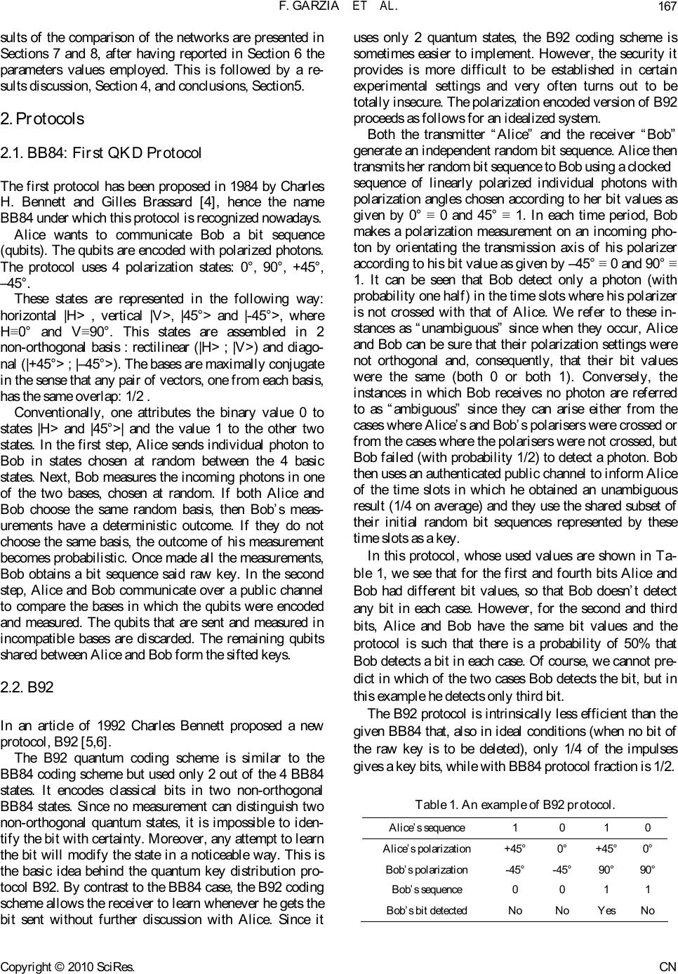 F. GARZIA ET AL.167 sults of the comparison of the networks are presented in Sections 7 and 8, after having reported in Section 6 the parameters values employed. This is followed by a re- sults discussion, Section 4, and conclusions, Section5. 2. Protocols 2.1. BB84: First QKD Protocol The first protocol has been proposed in 1984 by Charles H. Bennett and Gilles Brassard [4], hence the name BB84 unde r w hi c h t hi s pr ot o c ol is recognized nowa day s . Alice wants to communicate Bob a bit sequence (qubits). The qubits are encoded with polarized photons. The protocol uses 4 polarization states: 0°, 90°, +45°, –45°. These states are represented in the following way: horizontal |H> , vertical |V>, |45°> and |-45°>, where H≡0° and V≡90°. This states are assembled in 2 non-orthogonal basis : rectilinear (|H> ; |V>) and diago- nal (|+45°> ; |–45°>). The bases are maximally conjugate in the sense that any pair of vectors, one from each basis, has the same overlap: 1/2 . Conventionally, one attributes the binary value 0 to states |H> and |45°>| and the value 1 to the other two states. In the first step, Alice sends individual photon to Bob in states chosen at random between the 4 basic states. Next, Bob measures the incoming photons in one of the two bases, chosen at random. If both Alice and Bob choose the same random basis, then Bob’s meas- urements have a deterministic outcome. If they do not choose the same basis, the outcome of his measurement becomes probabilistic. Once made all the measurements, Bob obtains a bit sequence said raw key. In the second step, Alice and Bob communicate over a public channel to compare the bases in which the qubits were encoded and measured. The qubits that are sent and measured in incompatible bases are discarded. The remaining qubits shared between Alice and Bob form the sifted keys. 2.2. B92 In an article of 1992 Charles Bennett proposed a new protocol, B92 [5,6]. The B92 quantum coding scheme is similar to the BB84 coding scheme but used only 2 out of the 4 BB84 states. It encodes classical bits in two non-orthogonal BB84 states. Since no measurement can distinguish two non-orthogonal quantum states, it is impossible to iden- tify the bit with certainty. Moreover, any atte mpt to learn the bit will modify the state in a noticeable way. This is the basic idea behind the quantum key distribution pro- tocol B92. By contrast to the BB84 case, the B92 coding scheme allows the receiver to learn whenever he gets the bit sent without further discussion with Alice. Since it uses only 2 quantum states, the B92 coding scheme is sometimes easier to implement. However, the security it provides is more difficult to be established in certain experimental settings and very often turns out to be to tally in secu re. Th e polar izatio n en code d version of B92 proceeds as follows for an idealized system. Both the transmitter “Alice” and the receiver “Bob” generate an independent random bit sequence. Alice then transmits her random bit sequence t o Bob using a clocked sequence of linearly polarized individual photons with polarization angles chosen according to her bit values as given by 0° ≡ 0 and 45° ≡ 1. In each time period, Bob makes a polarization measurement on an incoming pho- ton by orientating the transmission axis of his polarizer according to his bit value as given by –45° ≡ 0 and 90° ≡ 1. It can be seen that Bob detect only a photon (with probability one half) in the time slots where h is polarizer is not crossed with that of Alice. We refer to these in- stances as “unambiguous” since when they occur, Alice and Bob can be sure that their polarization settings were not orthogonal and, consequently, that their bit values were the same (both 0 or both 1). Conversely, the instances in which Bob receives no photon are referred to as “ambiguous” since they can arise either from the cases where Alice’s and Bob’s polarisers were crossed or from the cases where the polarisers were not crossed, but Bob failed (with probability 1 /2) to detect a photon. Bob then uses an authen ticated public ch ann el to info rm Alice of the time slots in which he obtained an unambiguous result (1/4 on average) and they use the shared subset of their initial random bit sequences represented by these time slots as a key. In this protocol, whose used values are shown in Ta- ble 1, we see that for the first and fourth bits Alice and Bob had different bit values, so that Bob doesn’t detect any bit in each case. However, for the second and third bits, Alice and Bob have the same bit values and the protocol is such that there is a probability of 50% that Bob detects a bit in each case. Of course, we cannot pre- dict in which of the two cases Bob detects the bit, but in this example he detects only third bit. The B92 protocol is intrinsically less efficient than the given BB84 that, also in ideal conditions (when no bit of the raw key is to be deleted), only 1/4 of the impulses gives a key bits, whil e wi th B B 84 p rot ocol fraction is 1/ 2. Table 1. An example of B92 protocol. Alice’s sequence 1 0 1 0 Alice’s polarization +45° 0° +45°0° Bob’s polarization -45° -45° 90° 90° Bob’s sequence 0 0 1 1 Bob’s bit detected No No Yes No Copyright © 2010 SciRes. CN 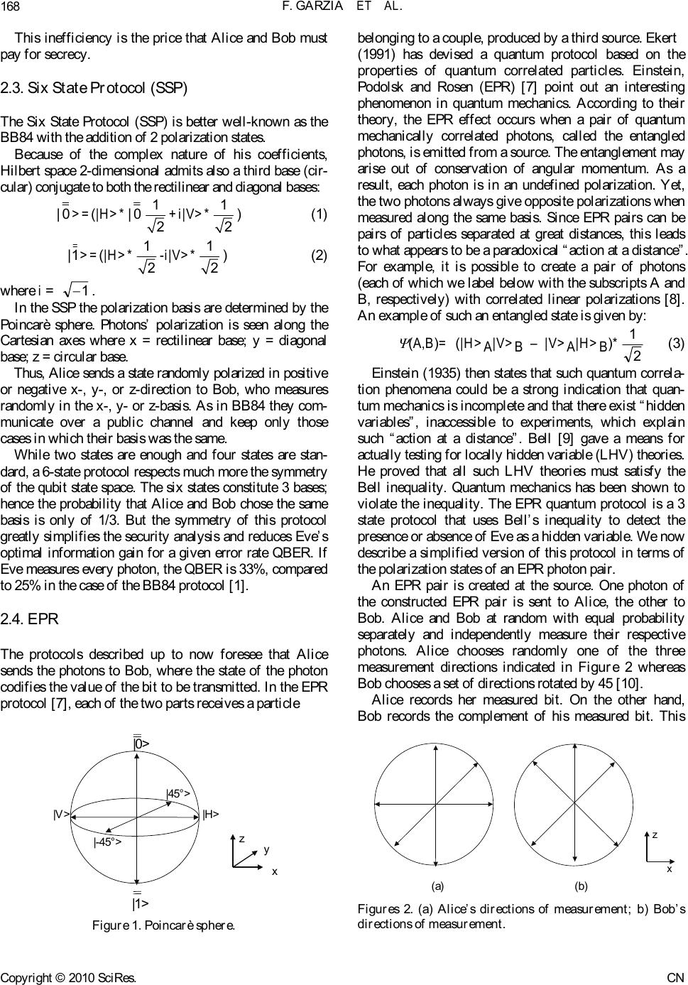 F. GARZIA ET AL. 168 This inefficiency is the price that Alice and Bob must pay for secrecy. 2.3. Six State Protocol (SSP) The Six State Protocol (SSP) is better well-known as the BB84 with the addi t i on of 2 polarization states. Because of the complex nature of his coefficients, Hilbert space 2-dimensional admits also a third base (cir- cular) conjugate to both the rectilinear and diagonal bases: |0>=(|H>*|0 1 2+i|V>* 1 2) (1) 1| >=(|H>* 1 2-i|V>* 1 2) (2) where i = 1. In the SSP the polarization basis are determined by the Poincarè sphere. Photons’ polarization is seen along the Cartesian axes where x = rectilinear base; y = diagonal base; z = circular base. Thus, Alice sends a state randomly polarized in positive or negative x-, y-, or z-direction to Bob, who measures randomly in the x-, y- or z-basis. As in BB84 they com- municate over a public channel and keep only those cases in which their basis was the same. While two states are enough and four states are stan- dard, a 6-state protocol respects much more the symmetry of the qubit state space. The six states constitute 3 bases; hence the probability that Alice and Bob chose the same basis is only of 1/3. But the symmetry of this protocol greatly simplifies the security analysis and reduces Eve’s optimal information gain for a given error rate QBER. If Eve measures every photon, the QBER is 33%, compared to 25% in the case of the BB8 4 protocol [ 1]. 2.4. EPR The protocols described up to now foresee that Alice sends the photons to Bob, where the state of the photon codifies the value of the bit to be transmitted. In the EPR protocol [7], each of the two parts receives a particle |H>|V> |0> |1> |-45°> |45°> z x y Figure 1. Poincarè sphere. belonging to a couple, produc ed by a third sou rce. Ekert (1991) has devised a quantum protocol based on the properties of quantum correlated particles. Einstein, Podolsk and Rosen (EPR) [7] point out an interesting phenomenon in quantum mechanics. According to their theory, the EPR effect occurs when a pair of quantum mechanically correlated photons, called the entangled photons, is emitted from a source. The entanglement may arise out of conservation of angular momentum. As a result, each photon is in an undefined polarization. Yet, the two photons always give opposite polar izations when measured along the same basis. Since EPR pairs can be pairs of particles separated at great distances, this leads to what appears to be a paradoxical “action at a distance”. For example, it is possible to create a pair of photons (each of which we label below with the subscripts A and B, respectively) with correlated linear polarizations [8]. An example of such an entangled state is given by: (A,B)= (|H>A|V>B – |V>A|H>B)*2 1 (3) Einstein (1935) then states that such quantum correla- tion phenomena could be a strong indication that quan- tum mechanics is incomplete and that there exist “hidden variables”, inaccessible to experiments, which explain such “action at a distance”. Bell [9] gave a means for actually tes ting for local ly hidden variab le (LHV) theor i es . He proved that all such LHV theories must satisfy the Bell inequality. Quantum mechanics has been shown to violate the inequality. The EPR quantum protocol is a 3 state protocol that uses Bell’s inequality to detect the presence or absence of Eve as a hidden variable. We now describe a simplified version of this protocol in terms of the polarization states of an EPR photon pair. An EPR pair is created at the source. One photon of the constructed EPR pair is sent to Alice, the other to Bob. Alice and Bob at random with equal probability separately and independently measure their respective photons. Alice chooses randomly one of the three measurement directions indicated in Figure 2 whereas Bob chooses a set of directions rotated by 45 [10]. Alice records her measured bit. On the other hand, Bob records the complement of his measured bit. This z x (a) (b) Figures 2. (a) Alice’s directions of measurement; b) Bob’s directions of measurement. Copyright © 2010 SciRes. CN 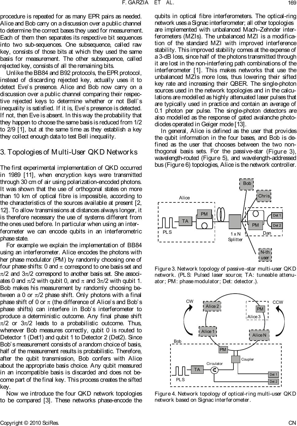 F. GARZIA ET AL.169 procedure is repeated for as many EPR pairs as needed. Alice and Bob carry on a discussion over a public channel to determine the correct bases they used for measurement. Each of them then separates its respective bit sequences into two sub-sequences. One subsequence, called raw key, consists of those bits at which they used the same basis for measurement. The other subsequence, called rejected key, consists of all the remaining bits. Unlike the BB84 and B92 protocols, the EPR protocol, instead of discarding rejected key, actually uses it to detect Eve’s presence. Alice and Bob now carry on a discussion over a public channel comparing their respec- tive rejected keys to determine whether or not Bell’s inequality is satisfied. If it is, Eve’s presence is detected. If not, then Eve is absent. In this way the probability that they happen to choose the same b asis is r educed from 1/2 to 2/9 [1], but at the same time as they establish a key they collect enough data to test Bell inequality. 3. Topologies of Multi-User QKD Networks The first experimental implementation of QKD occurred in 1989 [11], when encryption keys were transmitted through 30 cm of air using polarization-encoded photons. It was shown that the use of orthogonal states on more than 10 km of optical fibre is impossible, according to the characteristics of the sources available at present [2, 12]. To allow transmissions at distances always longer, it is therefore necessary the use of systems different from the ones used before. In particular when using an inter- ferometer we can encode qubits in an interferometric phase state. For example we explain the implementation of BB84 using an interferometer. Alice encodes the photons with her phase modulator (PM) by randomly choosing one of four phase shifts: 0 and correspond to one basis set and /2 and 3/2 correspond to another basis set. She associ- ates 0 and /2 with qubit 0, and and 3/2 with qubit 1. Bob makes his measurement by randomly choosing be- tween a 0 or /2 phase shift. Only photons with a final phase shift of 0 or (the difference of Alice’s and Bob’s phase shifts) can interfere in Bob’s interferometer to produce a deterministic outcome. Any final phase shift /2 or 3/2 leads to a probabilistic outcome. Thus, whenever Bob measures correctly, qubit 0 is routed to Detector 1 (Det1) and qubit 1 to Detector 2 (Det2). Since Bob’s measurement consists of a random choice of basis, half of the measurement results is probabilistic. Therefore, after the qubit transmission, Bob confers with Alice about the appropriate basis choice. Any qubit measured in an incompatible basis is discarded and does not be- come part of the final key. This process creates the sifted key. Now we introduce the four QKD network topologies to be compared [3]. These networks phase-encode the qubits in optical fibre interferometers. The optical-ring network uses a Signac interferometer; all other topologies are implemented with unbalanced Mach–Zehnder inter- ferometers (MZIs). The unbalanced MZI is a modifica- tion of the standard MZI with improved interference sta bility. This improved stability comes at the expense of a 3-dB loss, since half of the photons transmitted through it are lost in the non-interfering path combinations of the interferometer [1]. This makes networks that use the unbalanced MZIs more loss, thus lowering their sifted key rate and increasing their QBER. The single-photon sources used in the network topologies and in the calcu- lations are modelled as highly attenuated laser pulses that are typically used in practice and contain an average of 0.1 photon per pulse. The single-photon detectors are also modelled as the response of gated avalanche photo- diodes operated in Geiger mode [13]. In general, Alice is defined as the user that provides the qubit information in the four bases, and Bob is de- fined as the user that chooses between the two non- thogonal basis sets. For the passive-star (Figure 3), wavelength-routed (Figure 5), and wavelength-addressed bus (Figure 6) topologies, Alice is the network controller. TA TA TA PM PLS Alice 1 x N Splitter PM Det 1 Det 2 Dan Bob Chris N-th user Figure 3. Network topology of passive -star multi-user QKD network. (PLS: Pulsed laser source; TA: tuneable attenu- ator; PM: phase modulator; Det: detector.). TA PLS Circulator Coupler Det 1 Det 2 Bob Alice 1 Alice 2 Alice N PM Alice 3 PM CW CCW Figure 4. Network topology of optical-ring multi-user QKD network base d on Signac interferometer. Copyright © 2010 SciRes. CN 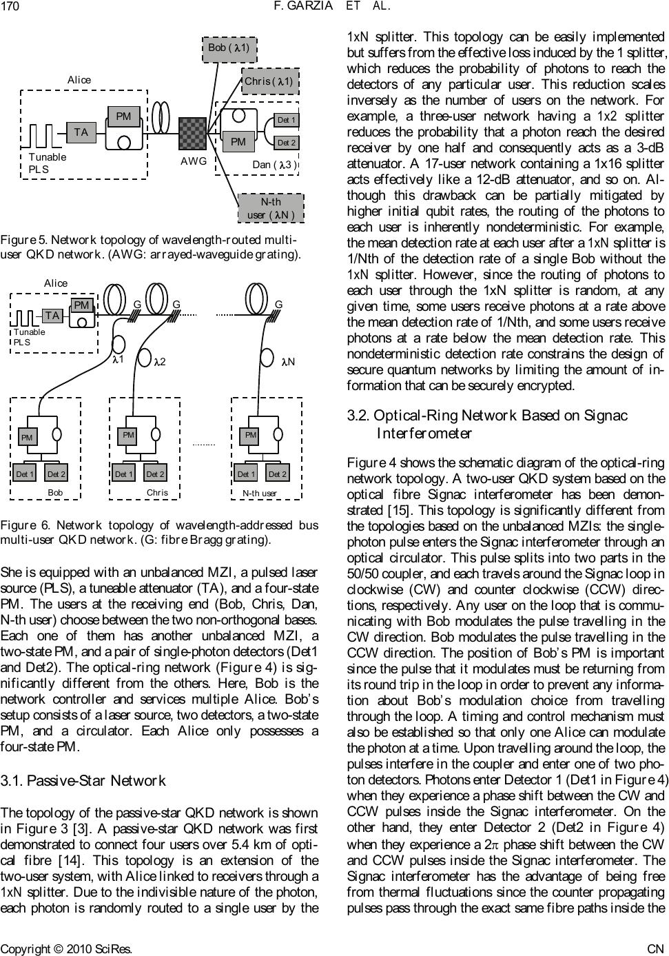 F. GARZIA ET AL. 170 TA TA TA PM Tunable PLS Alice AWG PM Det 1 Det 2 Dan( 3 ) Bob ( 1) Chris( 1) N-th user( N ) Figure 5. Network topology of wavelength-routed multi- user QKD network. (AWG: arrayed-waveguide grating). TA TA TA PM Tunable PLS Alic e GGG PM Det 1Det 2 Bob PM Det 1Det 2 Chris PM Det 1Det 2 N-th user 12N Figure 6. Network topology of wavelength-addressed bus multi-user QKD network. (G: fibre Bragg grating). She is equipped with an unbalanced MZI, a pulsed laser source (PLS), a tuneable attenuator (TA), and a four -stat e PM. The users at the receiving end (Bob, Chris, Dan, N-th user) choo se between the two non-o r thogon al bases. Each one of them has another unbalanced MZI, a two-state PM, and a pair of single-photon detectors (Det1 and Det2). The optical-ring network (Figure 4) is sig- nificantly different from the others. Here, Bob is the network controller and services multiple Alice. Bob’s setup consists of a laser source, two detectors, a two-state PM, and a circulator. Each Alice only possesses a four-state PM. 3.1. Passive-Star Network The topology of the passive-star QKD network is shown in Figure 3 [3]. A passive-star QKD network was first demonstrated to connect four users over 5.4 km of opti- cal fibre [14]. This topology is an extension of the two-user system, with Alice linked to receivers through a 1xN splitter. Due to the indivisible nature of the photon, each photon is randomly routed to a single user by the 1xN splitter. This topology can be easily implemented but suffers from the effective loss induced by the 1 splitter, which reduces the probability of photons to reach the detectors of any particular user. This reduction scales inversely as the number of users on the network. For example, a three-user network having a 1x2 splitter reduces the probability that a photon reach the desired receiver by one half and consequently acts as a 3-dB attenuator. A 17-user network containing a 1x16 splitter acts effectively like a 12-dB attenuator, and so on. Al- though this drawback can be partially mitigated by higher initial qubit rates, the routing of the photons to each user is inherently nondeterministic. For example, the mean detection rate at each user after a 1xN splitter is 1/Nth of the detection rate of a single Bob without the 1xN splitter. However, since the routing of photons to each user through the 1xN splitter is random, at any given time, some users receive photons at a rate above the mean detection rate of 1/Nth, and some users receive photons at a rate below the mean detection rate. This nondeterministic detection rate constrains the design of secure quantum networks by limiting the amount of in- formation that can be securely encrypted. 3.2. Optical-Ring Network Based on Signac Interferometer Figure 4 shows the schematic diagram of the optical- ring network topology. A two-user QKD system based on the optical fibre Signac interferometer has been demon- strated [15]. This topology is significantly different from the topologies based on the unbalanced MZIs: the single- photon pulse en ters the Signac interferometer throug h an optical circulator. This pulse splits into two parts in the 50/50 coupler, and each travels around the Signac loop in clockwise (CW) and counter clockwise (CCW) direc- tions, respectively. Any user on the loop that is commu- nicating with Bob modulates the pulse travelling in the CW direction. Bob modulates the pulse travelling in the CCW direction. The position of Bob’s PM is important since the pulse that it modulates must be returning from its round trip in the loop in order to prevent any informa- tion about Bob’s modulation choice from travelling through the loop. A timing and control mechanism must also be established so that only one Alice can modulate the photon at a time. Upon travelling around the loop, the pulses interfere in the coupler and enter one of two pho- ton detectors. Photons enter Detector 1 (Det1 in Figure 4) when they experience a phase shift between the CW and CCW pulses inside the Signac interferometer. On the other hand, they enter Detector 2 (Det2 in Figure 4) when they experience a 2 phase shift between the CW and CCW pulses inside the Signac interferometer. The Signac interferometer has the advantage of being free from thermal fluctuations since the counter propagating pulses pass through the exact same fibre paths inside the Copyright © 2010 SciRes. CN  F. GARZIA ET AL.171 loop. Another potential advantage is that each user on the network, except Bob, contains only a single-PM and no photon detectors. This can simplify any deployment of a secure ring network using the Signac because Bob is the only user that requires the single-photon detectors. 3.3. Wavelength-Routed Network The schematic diagram of the wavelength-routed net- work topology is depicted in Figure 5 [3]. This topo logy is implemented with unbalanced MZIs and is very similar in layout to the star network. The greater difference is that Alice has the ability to control which user receives the photons by employing a wavelength-routing scheme. Alice is equipped with a wavelength tuneable pulsed laser source (PLS) and the receivers are assigned their own wavelength channel. Alice transmits to a particular user by tuning her source to that user’s wavelength and the photons are routed via an arrayed waveguide grating (AWG). The advantage of this topology is that the inser- tion loss of the AWG is approximately uniform regard- less of the number of channels. Theoretically, the num- ber of users that this type of network supports is limited only by the channel spacing of the AWG and the band- width of the fibre. In addition, the single-photon detec- tors must be sensitive for the entire range of frequencies used in the network. This is not a concern as avalanche-photodiode (APD)-based single-photon de- tectors respond to a much broader spectrum than the band of wavelengths use d in multi-wavelength networks. Due to the principles of quantum mechanics described above, it is impossible for the spy Eve to gain perfect knowledge of the quantum state sent from Alice to Bob. Nevertheless, she can acquire some knowledge. Without interaction of a spy, each two-level quantum system carries 1 bit of information from Alice to Bob. When Eve gets hold of part of this information, she cannot prevent causing a disturbance to the state arriving at Bob’s side, and thus introducing a non-zero error rate. In principle, Bob can find out about this error rate and thus about the existence of a spy by communicating with Alice. The source for Eve’s knowledge is measurements performed on the signals (quantum states). The simplest eavesdrop- ping attack (intercept/resend) for Eve would be to meas- ure each signal just as Bob would do, and then to resend a signal to Bob which corresponds to the measurement result. Further we always have some detector noise, misalignments of detectors and so on. It should be pointed out that we cannot even in principle distinguish errors due to noise from errors due to eavesdropping activity. We therefore assume that all errors are due to eavesdropping. Another issue, not discussed here, is that of statistics. Eavesdroppers can be lucky: they create errors only on average, so in any specific realization the error rate might be zero (with probability exponentially small in the key length, of course). We are guided by the idea that a small error rate, for example 1 %, implies that an eavesdropper was not very active, while a big error rate is the signature of a serious eavesdropping attempt. But what is the meaning of “small” and “big”? From an information theoretic point of view, the natural measure of “knowledge” about some signal is represented by the Shannon information. It is measured in bits and can be defined for any two parties, the sender of the signal and the observer (receiver). In general terms, the knowledge of the observer consists of obtained measurement results and any additional gathered knowledge, like the an- nounced basis of signals in the BB84 protocol. 3.4. Wavelength-Addressed Bus Network The wavelength-addressed bus network is also based on the unbalanced MZI setup and it is shown in Figure 6 [3]. Like the wavelength-routed network, this network also allows Alice to route her photons to a desired user by tuning the photons to be desired wavelength. In such a system, Alice is equipped with a tuneable PLS, and each receiver is assigned its own wavelength channel. Alice selects an intended receiver by tuning her source to that user’s wavelength and transmits the encoded photons along the bus. The receivers are connected to the bus line through a fibre Bragg grating (G), which allows them to retrieve on ly the pho ton s, in tend ed for them. Th ese grating s are designed to reflect photons of a specific wavelength to a given user and transmit all others. The network accommodates multiple users by placing several fibre Bragg gratings in series along the bus. One of the merits of this topology is that it can be easily expanded to accommodate more users by simply tapping the bus and inserting a suitable grating. 4. Security Threshold The QBER, which is indicative of the security and post-error-correction net key rate, is useful for assessing the performance of the network. High QBER values in QKD systems lower the net key rate during the error correction stage of the protocol [1]. In addition, high QBER allows an eavesdropper to gain more information about the transmitted keys at the expense of the legiti- mate receiver. It has been shown that for QBERs above a security threshold, an eavesdropper can actually gain more information than the legitimate receiver. If this happens, it is not possible to use any privacy-amplification technique. Therefore, when designing a QKD network, it is necessary to ensure that the baseline QBER is below this security threshold so that privacy amplification strategies may be used to eliminate any knowledge Copyright © 2010 SciRes. CN  F. GARZIA ET AL. 172 gained by Eve [1]. For QBERs under this threshold (QBERT), the Shannon information between Alice and Bob (IAB) is higher than that in Eva’s possession (IE ), while for superior values that of Eva is greater: QBER < QBERT I AB > IE (4) QBER > QBERT I AB < IE (5) Bounds on the obtainable Shannon information for eavesdropping on single bits can be found in the litera- ture for different protocols. Fuchs et al. give bounds for the BB84 [16] and the B92 protocol [17]. A bound for the Six State Protocol was also obtained [18]. These bounds are illustrated in Figures 7–9 for each of used protocol. Note the trade-off between Eve’s information gain and the disturbance she causes: more information for Eve means higher error rate for Bob. For reasonably low error rates Eve’s maximal information is smallest in the six-state protocol, as it uses the largest ensemble of input states. Figure 7. Shannon Information (in normalized units) with B92 protocol. Figure 8. Shannon Information (in normalized units) with SSP. Figure 9. Shannon Information (in normalized units) with EPR protocol. Furthermore comparing Eva’s Shannon Information with the Shannon information between Alice and Bob, we are able to determinate the threshold for the QBER for each of the used protocols. 4.1. B92 Security Threshold for B92 protocol is: QBERT 14% (6) 4.2. SSP Security Threshold for the Six State Protocol is: QBERT 17% (7) 4.3. EPR Security Threshold for EPR protocol is: QBERT 15% (8) 5. Key Parameters in QKD QBER and RSIFT are two parameters used to gauge the performance of network topologies which offer QKD service. The QBER and sifted key rate equations that are used in the simulations are reviewed in this section. More detailed discussions on the physical principles underlying these equations are provided in references [1] and [19]. The sifted keys are those keys shared by Alice and Bob when they make compatible basis choices [19]: RSIFT = q RRAW (9) RRAW = fREP tLINK (raw key rate) (10) where q depends on protocol (for example, in BB84 pro- tocol q = 1/2 because half of the time Alice and Bob bases are not compatible), fREP is the repetition frequency, µ is the average number of photons per pulse, tLINK is the Copyright © 2010 SciRes. CN  F. GARZIA ET AL.173 transmission coefficient of the link and is Bob’s detec- tion efficiency. The transmission coefficient is related to the loss lF (in dB per km) and length L (in km) of the fibre, the loss due to the number of users lN(N) (in dB), and the topology selected, by tLINK = 10/ 10 TNF lNlLl (11) The topology choice introduces a topology loss con- stant lT (in dB) that is an overhead of loss involved in working with a particular topology. This quantity is con- stant regardless of a network’s fibre length and number of users. The topology loss has 4 components: end-user losses arising from losses in the receiver’s interferometer, routing loss caused by the device that selects the user that receives the photon, the non-interfering path combi- nation loss in the unbalanced MZIs (for those topologies that use them), and miscellaneous losses, such as those caused by connectors and splices. The QBER is defined as the number of wrong bits of the total number of received bits and is normally in the order of a few percent. In the following we use it ex- pressed as a function of rates [1]: SIFT error errorSIFT error R R RR R QBER (12) One can distinguish three different contributions to RERROR. The first one arises because of photons ending up in the wrong detector, due to imperfect interference or polarization contrast. The rate ROPT is given by the product of the sifted key rate and the probability POPT of a photon going in the wrong detector: ROPT = RSIFT POPT (13) This contribution can be considered, for a given set-up, as an intrinsic error rate indicating the suitability to use it for QKD. Imperfect phase matching in the interferometer s results in reduced fringe visibilities that lead to an increased probability of routing photons to the wrong detectors. The probability of this type of error POPT is related to the fringe visibility (V) by: POPT = 2 1V (14) The second contr ibution, RDARK, arises from the detec- tor dark counts (or from remaining environmental stray light in free space setups). This rate is independent of the bit rate and depends only on the characteristic of the photon counter [13]. Of course, only dark counts falling in a short time window when a photon is expected give rise to errors: RDARK = k fREP PDARK (15) where PDARK is the probability of registering a dark count per time-window and per detector, and the k factor is related to the fact that a dark count has a k % chance to happen with Alice and Bob having chosen incompatible bases (thus eliminated during sifting). Finally error counts can arise from uncorrelated photons, because of imperfect phot on sources: RACC = 2 1fREP tLINK PACC (16) This factor appears only in systems based on entangled photons, where the photons belonging to different pairs, but arriving in the same time window, ar e no t necessar ily in the same state. The quantity PACC is the probability to find a second pair within the time window, knowing that a first one was created. The QBER can now be expressed as follows: SIFT ACCDARKOPT R RRR QBER (17) 6. Parameter Values The results are based on calculations assuming the following parameter values, which are held constant for each topology [1,13,14,20,21] : Pulse repetition rate (fREP) 1 MHz Mean number of photon per p ulse ( ) 0.1 Detector efficiency @1310 nm ( ) 20% Detector efficiency @1550 nm ( ) 10% Dark count probability (PDARK ) 10-5 Fringe visibility (V) 98% The transmission coefficient link tLINK varies from one topology to another. The values used in the simulations that contribute to tLINK are outlined for each topology in Table 2. In the table the contributions to the topology losses are also shown; namely, the end- user loss, routing loss, non-interfering path combination loss, and miscel- laneous loss. The end-user loss arises from the excess loss in the couplers and PM in the receiver’s interferometer. Routing loss is th e lo ss in th e dev ic e th a t rou tes the phot ons to each user. In the star, wavelength-routed, and bus networks, which are all based on the unbalanced MZI design, a 3-dB loss arises from non-interfering path combinations. The miscellaneous loss stems from losses Table 2. Losses contributing to the transmission coefficient tLINK for the 4 considered network topologies. Loss SourceStar Ring W.RoutedBus Topology Loss End User Loss (dB) Routing Loss (dB) N on interfer. path Loss (dB) Miscellaneous Loss (dB) 0.3 0.1 3.0 1.0 0.49 0.0 0.0 1.0 0.3 3.0 3.0 1.0 0.3 0.02 3.0 1.0 Total Topology Loss (dB)4.4 1.49 7.34.32 Fiber Loss (dB/km)0.35 @ 1310 nm 0.25 @ 1550 nm User number Loss ( dB)10log(N) 0.1N 00.2(N-1) Copyright © 2010 SciRes. CN  F. GARZIA ET AL. 174 such as those due to connectors, splices, and imperfections in the network all of which occur in practical optical network setups. Now we are able to analyse the QBER and the RSIFT for every QKD protocol considered previously. The results of QBER for each topology are presented in sur- face plots which relate the QBER to the number of users and distance. The term “distance” is defined as the total fibre length used in the transmission of the photons. For the optical ring, it is the total length of the Signac loop. For all the other topologies, it is the total fibre length spanning Alice and Bob (or Chris, Dan, etc.). The system performances at the 1310-nm and 1550-nm telecommu- nications wavelength windows are shown in the results. The shaded regions in the QBER surface plots corre- spond to the combinations of distance and number of network users for which the QBER is less than QBERT. This threshold, previously mentioned in section IV, is the value below which secure key distribution can be per- formed on the network. Thus, the shape and area of the shaded regions allow one to easily determine the suit- ability of a given topology to support a given number of users. In addition, these plots also serve to show a net- work’s sensitivity to expanding the number of users. 7. QBER Performance 7.1. B92 As previously explained in section 2.2, B92 protocol is intrinsically less efficient than the given BB84 where, also in ideal conditions (when no bit of the raw key is to be deleted), only 1/4 of the impulses gives a key bits, while with BB84 this protocol fraction is 1/2. This in- efficiency is the price that Alice and Bob must pay for secrecy. RSIFT = 4 1RRAW =4 1 f REP tLINK (18) ROPT =4 1 f REP tLINK POPT (19) where POPT = 2 1V= 0.01 = 1% (20) since fringe visibility is 98%. RDARK = 2 1 f REP PDARK (21) The 3-D QBER surface of the four topologies using a carrier wavelength of 1310 nm is illustrated in Figure 10, and the 3-D QBER surface at 1550 nm is illustrated in Figure 11. Table 3 and Ta ble 4 summarize the informa- tion obtained from Figure 10 and Figure 11. 7.2. SSP As previously explained in Subsection 2.3, the six states (a) (b) (c) (d) Figure 10. B92-protocol topologies at 1310 nm. QBER sur- face as a function of users and distance. Users range: 2-128 users. Distance range: 0- 80 km. QBER<14% in shaded re- gion. (a) Passive Star B92 1310 nm; (b) Optical Ring B92 1310 nm; (c) Wavelength-routed B92 1310 nm; (d) Wave- length-addressed bus B92 1310 nm. Copyright © 2010 SciRes. CN  F. GARZIA ET AL.175 (a) (b) (c) (d) Figures 11: B92-protocol, topologies at 1550 nm. QBER surface as a function of users and distance. Users range: 2-128 users. Distance range: 0-80 km. QBER<14% in shaded region. (a) Passive Star B92 1550 nm; (b) Optical Ring B92 1550 nm; (c) Wavelength-routed B92 1550 nm; (d) Wavelength-addressed bus B92 1550 nm. Table 3. B92-protocol Maximum number of users sup- ported by every topology at different distance for QBER <14%. Distance (km) Star 1310 nm / 1550 nm Ring 1310 nm / 1550 nm W.routed 1310 nm / 1550 nm Bus 1310 nm / 1550nm 10 32/20 >128 / >128 >128/ >128 76/66 20 14/11 >128 / >128 >128/ >128 59/54 30 6/6 110/ 110 >128/ >128 41/41 40 2/3 75/85 >128/ >128 24/29 50 1/2 40/60 0/>128 6/ 16 60 0/1 5/35 0/0 0/4 70 0/0 0/10 0/0 0/0 80 0/0 0/0 0/0 0/0 Table 4. B92-protocol Maximum distance (km) supported by every topology for various number of users for QBER<14% . Number of users Star 1310 nm / 1550 nm Ring 1310 nm / 1550 nm W.routed 1310 nm / 1550 nm Bus 1310 nm / 1550 nm 20 15/10 55/66 44/50 42/47 40 7/0 50/58 44/50 31/31 60 2/0 44/50 44/50 19/15 80 0/0 38/42 44/50 8/0 100 0/0 32/34 44/50 0/0 120 0/0 27/26 44/50 0/0 constitute 3 bases, hence the probability that Alice and Bob chose the same basis is only of 1/3. This means that to determinate the sifted key, that Alice and Bob can share, an average of 2/3 of the received bits must be dis- carded. But the symmetry of this protocol greatly simpli- fies the security analysis and reduces Eve’s optimal information gain for a given e rro r rate QBER . RSIFT = 3 1RRAW =3 1 f REP tLINK (22) ROPT =3 1 f REP tLINK POPT (23) where POPT = 2 1V = 0.01 = 1%, since fringe visibility is 98%. RDARK = 3 2 f REP PDARK (24) The 3-D QBER surface of the four topologies using a carrier wavelength of 1310 nm is illustrated in Figure 12, and the 3-D QBER surface at 1550 nm is illustrated in Figure 13. Table 5 and Table 6 summarize the informa- tion obtained from Figure 12 and Figure 13. 7.3. EPR As previously explained in Subsection 2.4, in the EPR protocol, each of the two parts (Alice and Bob) receives a particle belonging to a couple, produced by a thirsource. Because this source is not perfect, it could generate Copyright © 2010 SciRes. CN  F. GARZIA ET AL. 176 (a) (b) (c) (d) Figures 12. SSP, topologies at 1310 nm. QBER surface as a function of users and distance. Users range: 2-128 users. Distance range: 0- 80 km. QBER<17% in shaded region. (a) Passive Star SSP 1310 nm; (b) Optical Ring SSP 1310 nm; (c) Wavelength-routed SSP 1310 nm; (d) Wavelength-ad- dressed bus SSP 1310 nm. Table 5. SSP. Maximum number of users supported by every topology at different distance for QBER <17%. Distance (km) Star 1310 nm / 1550 nm Ring 1310 nm / 1550 nm W.routed 1310 nm / 1550 nm Bus 1310 nm / 1550 nm 10 34/21 >128 / >128 >128 / >128 78/68 20 15/12 >128 / >128 >128 / >128 60/55 30 6/6 113 /113 >128 / >128 43/43 40 3/3 78 /88 >128 / >128 25/30 50 1/2 43 /63 0/ >128 8/18 60 0/1 8 /38 0/0 0/5 70 0/0 0 /13 0/0 0/0 80 0/0 0/0 0/0 0/0 Table 6. SSP. Maximum distance (km) supported by every topology for various number of users for QBER<17%. Number of users Star 1310 nm / 1550 nm Ring 1310 nm / 1550 nm W.routed 1310 nm / 1550 nm Bus 1310 nm / 1550 nm 20 16/11 56/67 45/52 43/48 40 8/0 50/59 45/52 31/32 60 3/0 45/51 45/52 20/16 80 0/0 39/43 45/52 9/0 100 0/0 33/35 45/52 1/0 120 0/0 28/27 45/52 0/0 uncorrelated photons that generate error counts (RACC). The photons belonging to different pairs, not necessarily in the same state, could arrive in the same time window with probability PACC. Furthermore the EPR protocol, instead of discarding rejected key, actually uses it to detect Eve’s presence. By a discussion over a public channel, Alice and Bob compare their respective rejected keys to determine whether or not Bell’s inequality is satisfied. If it is, Eve’s presence is detected. If not, then Eve is absent. In this way the probability that they happen to choose the same basis is reduced from 1/2 to 2/9 [1], but at the same time as they establish a key they collect enough data to test Bell inequality. RSIFT = 9 2RRAW =9 2 f REP tLINK (25) ROPT =9 2 f REP tLINK POPT (26) where POPT = 1%. RDARK = 9 7 f REP PDARK (27) RACC = 2 1fREP tLINK PACC (28) Copyright © 2010 SciRes. CN  F. GARZIA ET AL.177 PACC = 2 1 2 = 000.5 (29) The 3-D QBER surface of the four topologies using a carrier wavelength of 1310 nm is illustrated in Figure 14, and the 3-D QBER surface at 1550 nm is illustrated in Figure 15. Tabl e 7 and Table 8 summarize the informa- tion obtained from Figure 14 and Figure 15. 8. RSIFT Performance To be able to make more visible the difference between the various topologies, we compare the sifted key rate of each topology as a function of distance for 4, 32, 64, 128 users. They were obviously assembled for every used protocol. The Sifted Key Rate performances of the four network topologies are the same for each used protocol. We use a grading system ranging from 1–4, where 1 indicates the network topology with the best performance, and 4 indi- cates the network topology with the worst performance, to summarize the results of the comparison of the sifted key rate performance of the network topologies. This is shown in Table 9. Another observation that is made is the distance (30 km) that the 1550- and 1310-nm sifted key rate lines for a particular network cross each other. This distance, which we conveniently call th e crossover distance, is the same for all four topologies and determines when the sifted key rate v alues at 1550 nm are greater or less than the key rates at 1310 nm. For distances less than the crossover distance, the sifted key rate values at 1310 nm are always greater than at 1550 nm. The situation reverses for distances beyond the cross- over distance so that the sifted key rate values at 1550 nm become greater. 9. Results Discussion Passive star network, that at first glance appears to be the easiest to implement, turns out to be the wor st net topology because: 1) supports the smallest number of users for any given distance; 2) is very sensitive to change in the distance and/or in number of the users; 3) has the lowest RSIFT . Furthermore it requires each user to have their own interferometer and photo-detectors. From this point of view, the ring topology is the simpler design, requiring each user to have only one four-state. Optical ring network is characterized from: 1) higher stability against polarization and phase fluctuations than the other three topologies since each pulse travels through the same fibre length in both the CW and CCW directions [2 2] ; (a) (b) (c) (d) Figure 13. EPR- protocol, topologies at 1310 nm. QBER surface as a function of users and distance. Users range: 2-128 users. Distance range: 0-80 km. QBER < 15% in shaded region. (a) Passive Star EPR 1310 nm; (b) Optical Ring EPR 1310 nm; (c) Wavelength-routed EPR 1310 nm; (d) Wavelength-addressed bus EPR 1310 nm. Copyright © 2010 SciRes. CN  F. GARZIA ET AL. 178 (a) (b) (c) (d) Figure 14. EPR- protocol, topologies at 1550 nm. QBER surface as a function of users and distance. Users range: 2-128 users. Distance range: 0-80 km. QBER < 15% in shaded region. (a) Passive Star EPR 1550 nm; (b) Optical Ring EPR 1550 nm; (c) Wavelength-routed EPR 1550 nm; (d) Wavelength-addressed bus EPR 1550 nm. Table 7. EPR-protocol Maximum number of users sup- ported by every topology at different distance for QBER < 15%. Dis- tance (km) Star 1310 nm /1550 nm Ring 1310 nm /1550 nm W.routed 1310 nm / 1550 nm Bus 1310 nm /1550 nm 10 3/1 79 / 58 >128/ >128 26/16 20 1/1 44 / 33 0/ 0 8/3 30 0/0 9/9 0/ 0 0/0 40 0/0 0/0 0/0 0/0 50 0/0 0/0 0/0 0/0 60 0/0 0/0 0/0 0/0 70 0/0 0/0 0/0 0/0 80 0/0 0/0 0/0 0/0 Table 8. EPR-protocol Maximum distance (km) supported by every topology for various number of users for QBER < 15%. Number of users Star 1310 nm / 1550 nm Ring 1310 nm / 1550 nm W.routed 1310 nm / 1550 nm Bus 1310 nm / 1550 nm 20 0/0 26/25 15/10 13/7 40 0/0 21/17 15/10 2/0 60 0/0 15/9 15/10 0/0 80 0/0 9/1 15/10 0/0 100 0/0 4/0 15/10 0/0 120 0/0 0/0 15/10 0/0 Table 9. Comparison of the Sifted Key Rate performance for the 4 network topologies. Number of users Passive star Optical ring W.routed Bus 4 4 1 3 2 32 4 1 2 3 64 4 1 1 3 128 3 2 1 4 2) lowest structure loss (1.49 dB, Table2); 3) lowest QBER with less than 64 users; 4) highest Sifted Key Rate with less than 64 us ers 5) being more susceptible to Trojan horse attacks than systems based on the unbalanced MZI [3]. Wavelength ne twork: 1) is the most suitable for networks with more than 64 users, because its Sifted key Rate is independent of the number of users on the network; 2) it may not be the best choice for networks that are not expected to expand beyond 64 users because since it has the highest structure loss (7.3 dB). Copyright © 2010 SciRes. CN  F. GARZIA ET AL.179 Figure 15. B92-protocol Sifted Key Rate versus distance for 4, 32, 64, 128 users. Figure 16. SSP. Sifted Key Rate versus distance for 4, 32, 64, 128 users. Copyright © 2010 SciRes. CN  F. GARZIA ET AL. 180 Figure 17. EPR-protocol. Sifted Key Rate versus distance for 4, 32, 64, 128 users. Wavelength-addressed-bus network: 1) is the most favourable for networks with less than 20 users because it can be easily expanded and has moderate structure loss (4.32 dB); 2) is unadvisable for networks with large number of users because it has a higher per-user loss than the ring network. It has also been shown that there is a crossover dis- tance (30 km) that determines the optimum wavelength (1310 or 1550 nm) to use in the QKD network. About QKD analyzed protocol only B92 and SSP turned out the most efficient. The EPR protocol is the less efficient. The difficulty to handle couples of particles without changing their correlation does no t allow to obtai n high performances. The results obtained at the moment are the least encouraging for all the four net topologies. The maximum reachable distance was of 30 km with 9 user maximum using the Optical-Ring topology. Only for distances lower than 10 km it is possible to obtain sufficient performances avoiding however the Passive-Star topology. Six States Protocol and the B92 present praiseworthy results. The B92 is the protocol of QKD more used and allows to make less communications on public channel. Six State Protocol prevails on everybody because, having a security threshold of 17%, allows to have a high number of users also beyond the 60 km, furthermore it has the fastest Sifted Key Rate. Commonly used technologies and techniques have been applied in order to evaluate the performances (QBER and Sifted Key Rate). To avoid that Eva can take some photons and measure their polarization without disturbing the one of the photons which arrives to Bob, it was considered an attenuation of the transmitted radia- tion, obtaining an average 0.1 photons per impulse. Commonly used technologies and techniques have been applied in order to evaluate the performances (QBER and Sifted Key Rate). Furthermore we considered pho- ton-detectors with efficiency of 10% at 1550 nm and 20% at 1310 nm. Obviously, this choice implies a non- neglectable reduction of the performances, but this com- promise solution has been chosen to operate a more realistic analysis. Technological improvements in single-photon detectors are able to reduce the number of photons lost and therefore to increase the system performances. 10. Conclusions In this paper the performances of four passive optical network topologies in implementing multi-user QKD, using 3 protocols proposed by quantum cryptography (B92, EPR, and SSP) have been compared. The QBER and sifted key rate for each of these topologies have been analysed to determine their suitability for providing service to networks of vari ous sizes. Copyright © 2010 SciRes. CN  F. GARZIA ET AL.181 11. References [1] N. Gisin, G. Ribordy, W. Tittel and H. Zbinden, “Quan- tum Cryptography,” Reveiw of Modern Physics, Vol. 2, Septemner 2001, pp. 1-57. [2] W. K. Wootters and W. Zurek, “A Single Quantum Can- not be Cloned,” Nature, Vol. 299, London, 1982. pp. 802-803. [3] P. Kumavor, A. Beal, S. Yelin, E. Donkor and B. Wang, “Comparison of Four Multi-user Quantum Key Distribu- tion Schemes Over Passive Optical Networks,” Journal of Lightwave Technology, Vol 23, No.1 January 2005, p.268. [4] C. H. Bennett and G. Brassard, “Quantum Cryptography: Public Key Distribution and Coin Tossing,” IEEE Conference on Computers, Systems Signal Processing, Bangalore, 1984. [5] C. Bennett, “Quantum Cryptography Using Any Two Non-orthogonal States,” Physical Review Letter, Vol. 68, 1992, p. 3121, [6] K. J. Gordon, V. Fernandez, P. D. Townsend and G. S. Buller, “A Short Wavelength Giga Hertz Clocked Fiber-Optic Quantum Key Distribution System,” IEEE Journal of Quantum Electronics, Vol 40, No7, July 2004, pp. 900-908. [7] A. Einstein, B. Podolsky and N. Rosen, “Can Quantum- Mechanical Description of Physical Reality be Considered Complete,” Physical Review, Vol. 41, May 1935, p. 777. [8] M. M. Ishtiaq Khan and M. Sher, “Protocols for Secure Quantum Transmission: A Review of Recent Develop- ments,” Pakistan Journal of Information and Technology, Vol. 2, No. 3, 2003, pp. 265-276. [9] J. Bell, “On the Einstein, Podolsky, Rosen Paradox,” Physics, Vol. 1, 1964, pp. 195-200. [10] D. Bruß and N. Lutkenhaus, “Quantum Key Distribution: From Principles to Practicalities,” Vol. 2, September 1999. [11] C. Bennett, F. Bessette, G. Brassard, L. Salvail and J. Smolin, “Experimental Quantum Cryptography,” Journal of Cryptography, Vol. 5, No. 1, 1992, pp. 3-28. [12] A. Muller, J. Breguet and N. Gisin, “Experimental Demonstration of Quantum Cryptography Using Pola- rized Photons in Optical Fiber Over More Than 1 km,” Europhysics Letter, Vol. 23, 1993, pp. 383-388. [13] D. Stucki et al., “Photon Counting for Quantum Key Distribution with Peltier Cooled InGaAs/InP APD’s,” Journal of Modern Optics, Vol. 48, No. 13, 2001, pp. 1967-1981. [14] P. D. Townsend, “Quantum Cryptography on Multi-User Optical Fiber Networks,” Journal of Nature, Vol. 385, No.2, 1997, pp. 47-49. [15] T. Nishioka, H. Ishizuka, T. Hasegawa and J. Abe, “Circular Type Quantum Key Distribution,” IEEE Photon Technical Letter, Vol. 14, No. 4, April 2002, pp. 576-578. [16] C. A. Fuchs, N. Gisin, R. B. Griffiths, C. S. Niu and A. Peres, “Optimal Eavesdropping in Quantum Crypto- graphy I,” P hysical Review A, Vol. 56, 1997, pp. 1163. [17] C. A. Fuchs and A. Peres, “Quantum State Disturbance VS. Information Gain: Uncertainty Relations for Quantum Information,” Physical Review A, Vol. 53, 1996, pp. 2038-2045. [18] D. Bruß, “Optimal Eavesdropping in Quantum Crypto- graphy With Six States,” Physical Reveiw Letter, Vol. 81, 1998, p. 3018. [19] D. Stucki, N. Gisin, O. Guinnard, G. Ribordi and H. Zbinden, “Quantum Key Distribution over 67 km with a Plug&Play System,” New Journal of Physics, Vol. 4, July 2002, pp. 1-8. [20] P. A. Hiskett et al., “Eighty Kilometer Transmission Experiment Using an InGaAs/InP SPAD-based Quantum Cryptography Receiver Operating at 1.55 m,” Journal of Modern Optics, Vol. 48, No. 13, July 2001, pp. 1957-1966. [21] D. S. Bethune and W. P. Risk, “Autocompensating Quan- tum Cryptography,” New Journal of Physics, Vol. 4, July 2002, pp. 1-15. [22] X. Fang and R. O. Claus, “Polarization-Dependent All- fiber Wavelength Division Multiplexer Based on a Signac Interferometer,” Optical Letter, Vol. 20, No. 20, October 1995, pp. 2146-2148. [23] P. D. Townsend, J. G. Rarity and P. R. Tapste r, “Enhanced Single Photon Fringe Visibility in a 10 km-long Prototype Quantum Cryptography Channel,” Electronics Letter, Vol. 29, July 1993, pp. 1291-1293. [24] C. Marand and P. D. Townsend, “Quantum Key Distri- bution over Distances as Long as 30 km,” Optical Letter, Vol. 20, No. 16, August 1995, pp. 1695-1697. [25] H. Zbinden, “Interferometry With Faraday Mirrors for Quantum Cryptography,” Electronics Letter, Vol. 33, 1997, pp. 586-588. [26] H. Kosaka, A. Tomita, Y. Nambu, N. Kimura and K. Nakamura, “Single Photon Interference Experiment over 100 km for Quantum Cryptography System Using a Balanced Gated-Mode Photon Detector,” Electronics Letter, Vol. 39, No. 16, 2003, pp. 1199-1201. [27] S. J. D. Phoenix et al., “Multi-User Quantum Crypto- graphy on Optical Networks,” Journal of Modern Optics, Vol. 42, No. 6, January 1995, pp. 1155–1163. [28] A. Muller, T. Herzog, B. Huttner, W. Tittel, H. Zbinden, and N. Gisin, “Plug and Play Systems for Quantum Cryptography,” Applied Physics Letter, Vol. 70, No. 7, February 1997, pp. 793–795. [29] E. Waks et al., “Secure Communication: Quantum Cryptography with a Photon Turnstile,” Nature, Vol. 420, London, December 2002, p. 762. [30] E. Moreau et al., “Single-Mode Solid-State Single Photon Source Based on Isolated Quantum Dots in Pillar Microcavities,” Applied Physcis Letter, Vol. 79, No. 18, October 2001, pp. 2865-2867. [31] H. Bechmann-Pasquinucci and N. Gisin, “Incoherent and Coherent Eavesdropping in the 6-state Protocol of Copyright © 2010 SciRes. CN  F. GARZIA ET AL. Copyright © 2010 SciRes. CN 182 Quantum Cryptography,” Physical Review A, Vol. 59, No. 6, 1998, pp. 1-11. [32] A. Ekert, “Quantum Cryptography Based on Bell's Theorem,” Physical Review Letter, Vol. 67, 1991, pp. 661-663. [33] R. J. Hughes, G. L. Morgan and C. G. Peterson, “Practical Quantum Key Distribution over a 48-km Optical Fiber Network,” Physics Division Los Alamos National Liberatory, NM 87545. |