Paper Menu >>
Journal Menu >>
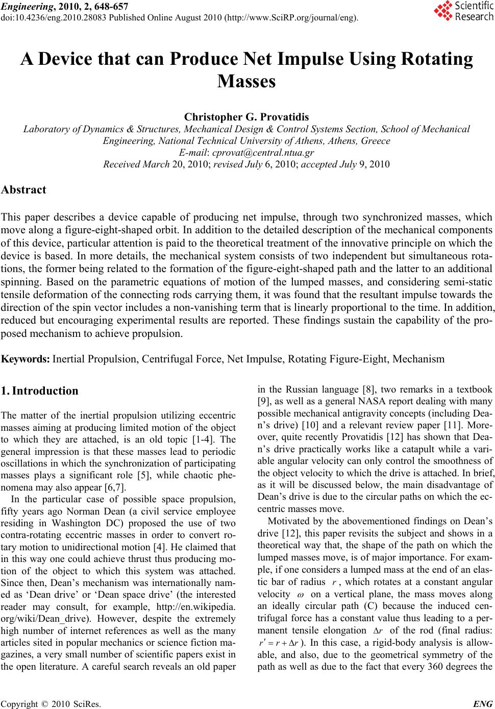 Engineering, 2010, 2, 648-657 doi:10.4236/eng.2010.28083 Published Online August 2010 (http://www.SciRP.org/journal/eng). Copyright © 2010 SciRes. ENG A Device that can Produce Net Impulse Using Rotating Masses Christopher G. Provatidis Laboratory of Dynamics & Structures, Mechanical Design & Control Systems Section, School of Mechanical Engineering, National Technical University of Athens, Athens, Greece E-mail: cprovat@central.ntua.gr Received March 20, 2010; revised July 6, 2010; accepted July 9, 2010 Abstract This paper describes a device capable of producing net impulse, through two synchronized masses, which move along a figure-eight-shaped orbit. In addition to the detailed description of the mechanical components of this device, particular attention is paid to the theoretical treatment of the innovative principle on which the device is based. In more details, the mechanical system consists of two independent but simultaneous rota- tions, the former being related to the formation of the figure-eight-shaped path and the latter to an additional spinning. Based on the parametric equations of motion of the lumped masses, and considering semi-static tensile deformation of the connecting rods carrying them, it was found that the resultant impulse towards the direction of the spin vector includes a non-vanishing term that is linearly proportional to the time. In addition, reduced but encouraging experimental results are reported. These findings sustain the capability of the pro- posed mechanism to achieve propulsion. Keywords: Inertial Propulsion, Centrifugal Force, Net Impulse, Rotating Figure-Eight, Mechanism 1. Introduction The matter of the inertial propulsion utilizing eccentric masses aiming at producing limited motion of the object to which they are attached, is an old topic [1-4]. The general impression is that these masses lead to periodic oscillations in which the synchronization of participating masses plays a significant role [5], while chaotic phe- nomena may also appear [6,7]. In the particular case of possible space propulsion, fifty years ago Norman Dean (a civil service employee residing in Washington DC) proposed the use of two contra-rotating eccentric masses in order to convert ro- tary motion to unidirectional motion [4]. He claimed that in this way one could achieve thrust thus producing mo- tion of the object to which this system was attached. Since then, Dean’s mechanism was internationally nam- ed as ‘Dean drive’ or ‘Dean space drive’ (the interested reader may consult, for example, http://en.wikipedia. org/wiki/Dean_drive). However, despite the extremely high number of internet references as well as the many articles sited in popular mechanics or science fiction ma- gazines, a very small number of scientific papers exist in the open literature. A careful search reveals an old paper in the Russian language [8], two remarks in a textbook [9], as well as a general NASA report dealing with many possible mechanical antigravity concepts (including Dea- n’s drive) [10] and a relevant review paper [11]. More- over, quite recently Provatidis [12] has shown that Dea- n’s drive practically works like a catapult while a vari- able angular velocity can only control the smoothness of the object velocity to which the drive is attached. In brief, as it will be discussed below, the main disadvantage of Dean’s drive is due to the circular paths on which the ec- centric masses move. Motivated by the abovementioned findings on Dean’s drive [12], this paper revisits the subject and shows in a theoretical way that, the shape of the path on which the lumped masses move, is of major importance. For exam- ple, if one considers a lumped mass at the end of an elas- tic bar of radius r, which rotates at a constant angular velocity on a vertical plane, the mass moves along an ideally circular path (C) because the induced cen- trifugal force has a constant value thus leading to a per- manent tensile elongation r of the rod (final radius: rr r ). In this case, a rigid-body analysis is allow- able, and also, due to the geometrical symmetry of the path as well as due to the fact that every 360 degrees the 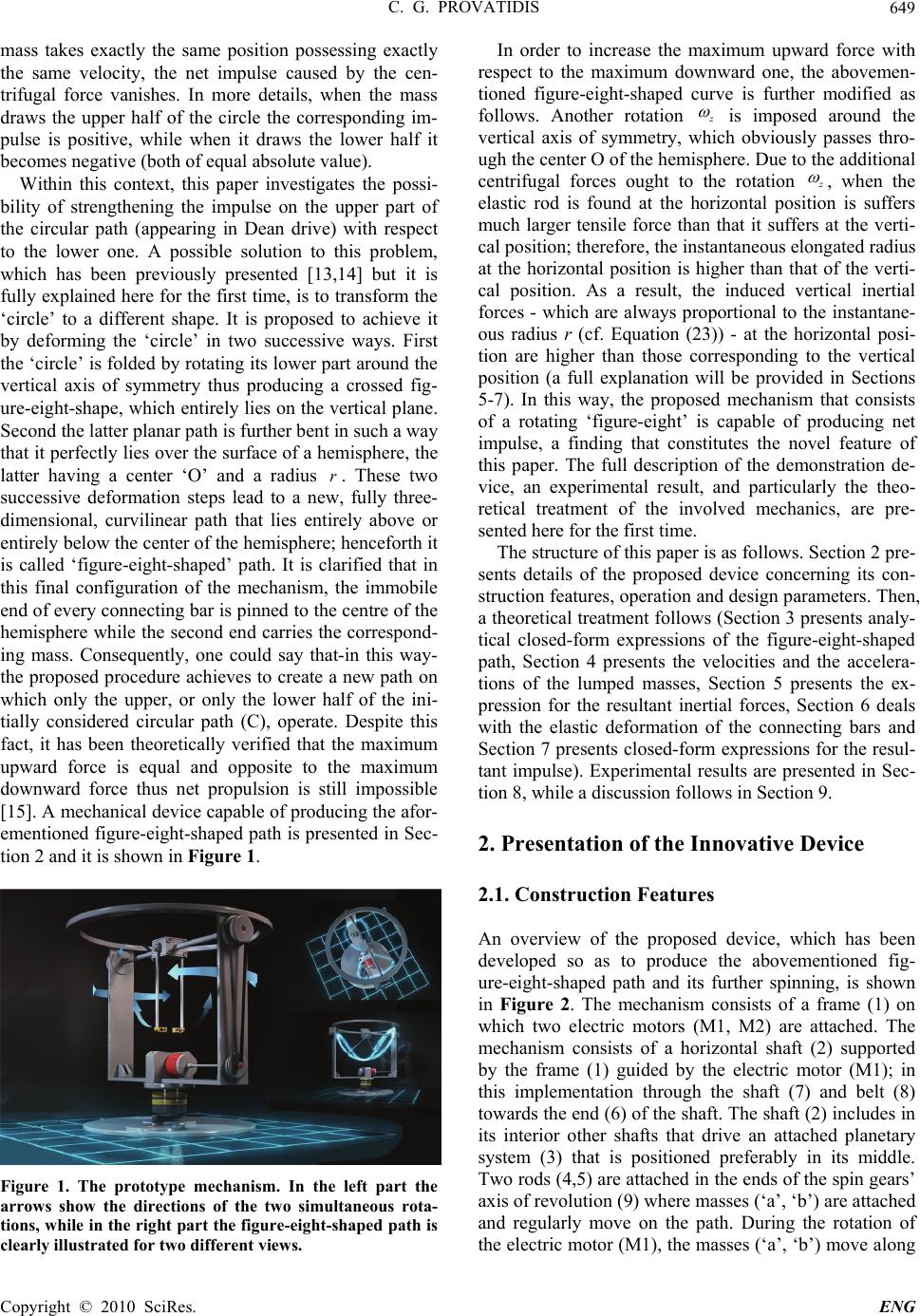 C. G. PROVATIDIS Copyright © 2010 SciRes. ENG 649 mass takes exactly the same position possessing exactly the same velocity, the net impulse caused by the cen- trifugal force vanishes. In more details, when the mass draws the upper half of the circle the corresponding im- pulse is positive, while when it draws the lower half it becomes negative (both of equal absolute value). Within this context, this paper investigates the possi- bility of strengthening the impulse on the upper part of the circular path (appearing in Dean drive) with respect to the lower one. A possible solution to this problem, which has been previously presented [13,14] but it is fully explained here for the first time, is to transform the ‘circle’ to a different shape. It is proposed to achieve it by deforming the ‘circle’ in two successive ways. First the ‘circle’ is folded by rotating its lower part around the vertical axis of symmetry thus producing a crossed fig- ure-eight-shape, which entirely lies on the vertical plane. Second the latter planar path is further bent in such a way that it perfectly lies over the surface of a hemisphere, the latter having a center ‘O’ and a radius r. These two successive deformation steps lead to a new, fully three- dimensional, curvilinear path that lies entirely above or entirely below the center of the hemisphere; henceforth it is called ‘figure-eight-shaped’ path. It is clarified that in this final configuration of the mechanism, the immobile end of every connecting bar is pinned to the centre of the hemisphere while the second end carries the correspond- ing mass. Consequently, one could say that-in this way- the proposed procedure achieves to create a new path on which only the upper, or only the lower half of the ini- tially considered circular path (C), operate. Despite this fact, it has been theoretically verified that the maximum upward force is equal and opposite to the maximum downward force thus net propulsion is still impossible [15]. A mechanical device capable of producing the afor- ementioned figure-eight-shaped path is presented in Sec- tion 2 and it is shown in Figure 1. Figure 1. The prototype mechanism. In the left part the arrows show the directions of the two simultaneous rota- tions, while in the right part the figure-eight-shaped path is clearly illustrated for two different views. In order to increase the maximum upward force with respect to the maximum downward one, the abovemen- tioned figure-eight-shaped curve is further modified as follows. Another rotation z is imposed around the vertical axis of symmetry, which obviously passes thro- ugh the center O of the hemisphere. Due to the additional centrifugal forces ought to the rotation z , when the elastic rod is found at the horizontal position is suffers much larger tensile force than that it suffers at the verti- cal position; therefore, the instantaneous elongated radius at the horizontal position is higher than that of the verti- cal position. As a result, the induced vertical inertial forces - which are always proportional to the instantane- ous radius r (cf. Equation (23)) - at the horizontal posi- tion are higher than those corresponding to the vertical position (a full explanation will be provided in Sections 5-7). In this way, the proposed mechanism that consists of a rotating ‘figure-eight’ is capable of producing net impulse, a finding that constitutes the novel feature of this paper. The full description of the demonstration de- vice, an experimental result, and particularly the theo- retical treatment of the involved mechanics, are pre- sented here for the first time. The structure of this paper is as follows. Section 2 pre- sents details of the proposed device concerning its con- struction features, operation and design parameters. Then, a theoretical treatment follows (Section 3 presents analy- tical closed-form expressions of the figure-eight-shaped path, Section 4 presents the velocities and the accelera- tions of the lumped masses, Section 5 presents the ex- pression for the resultant inertial forces, Section 6 deals with the elastic deformation of the connecting bars and Section 7 presents closed-form expressions for the resul- tant impulse). Experimental results are presented in Sec- tion 8, while a discussion follows in Section 9. 2. Presentation of the Innovative Device 2.1. Construction Features An overview of the proposed device, which has been developed so as to produce the abovementioned fig- ure-eight-shaped path and its further spinning, is shown in Figure 2. The mechanism consists of a frame (1) on which two electric motors (M1, M2) are attached. The mechanism consists of a horizontal shaft (2) supported by the frame (1) guided by the electric motor (M1); in this implementation through the shaft (7) and belt (8) towards the end (6) of the shaft. The shaft (2) includes in its interior other shafts that drive an attached planetary system (3) that is positioned preferably in its middle. Two rods (4,5) are attached in the ends of the spin gears’ axis of revolution (9) where masses (‘a’, ‘b’) are attached and regularly move on the path. During the rotation of the electric motor (M1), the masses (‘a’, ‘b’) move along 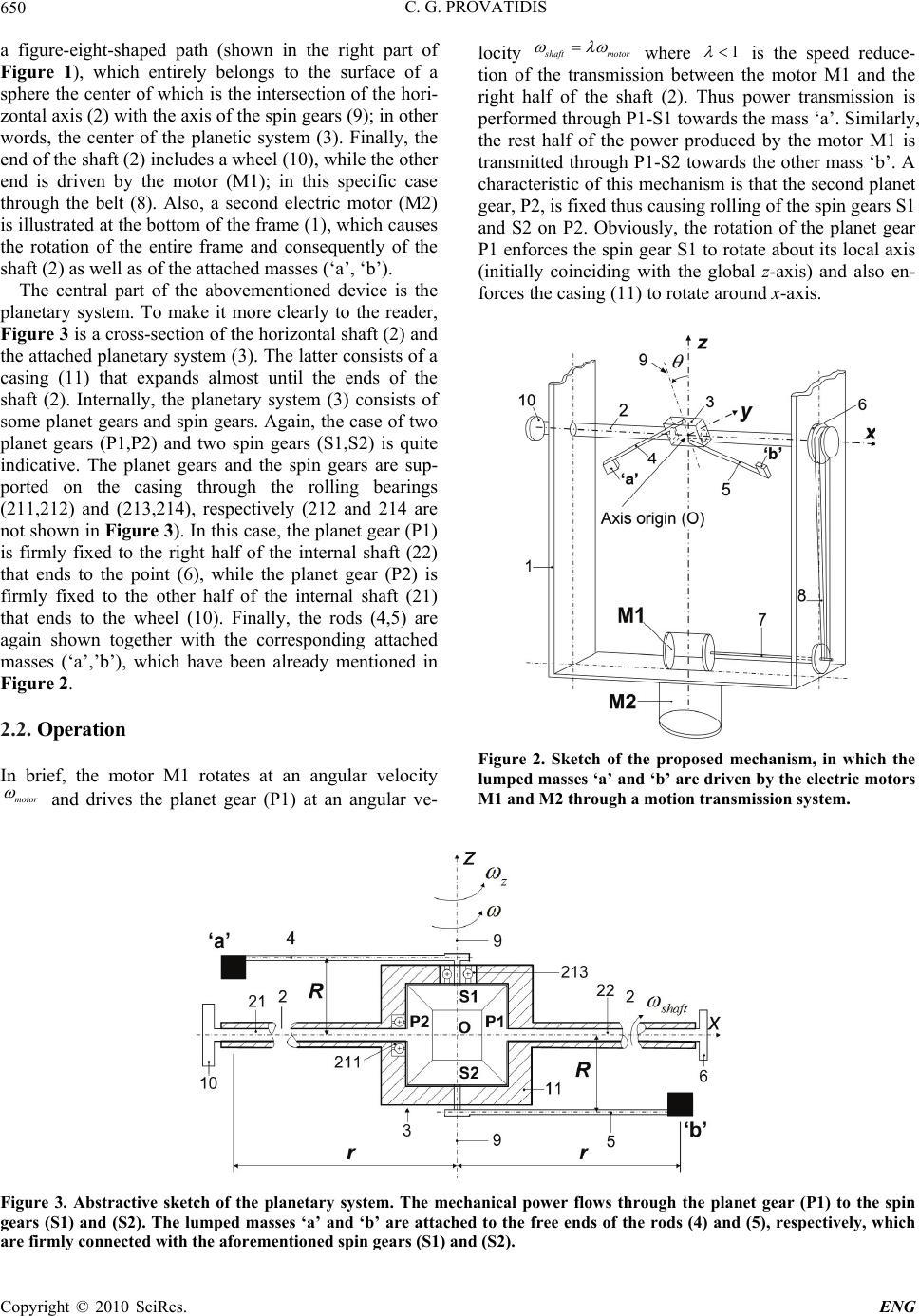 C. G. PROVATIDIS Copyright © 2010 SciRes. ENG 650 a figure-eight-shaped path (shown in the right part of Figure 1), which entirely belongs to the surface of a sphere the center of which is the intersection of the hori- zontal axis (2) with the axis of the spin gears (9); in other words, the center of the planetic system (3). Finally, the end of the shaft (2) includes a wheel (10), while the other end is driven by the motor (M1); in this specific case through the belt (8). Also, a second electric motor (M2) is illustrated at the bottom of the frame (1), which causes the rotation of the entire frame and consequently of the shaft (2) as well as of the attached masses (‘a’, ‘b’). The central part of the abovementioned device is the planetary system. To make it more clearly to the reader, Figure 3 is a cross-section of the horizontal shaft (2) and the attached planetary system (3). The latter consists of a casing (11) that expands almost until the ends of the shaft (2). Internally, the planetary system (3) consists of some planet gears and spin gears. Again, the case of two planet gears (P1,P2) and two spin gears (S1,S2) is quite indicative. The planet gears and the spin gears are sup- ported on the casing through the rolling bearings (211,212) and (213,214), respectively (212 and 214 are not shown in Figure 3). In this case, the planet gear (P1) is firmly fixed to the right half of the internal shaft (22) that ends to the point (6), while the planet gear (P2) is firmly fixed to the other half of the internal shaft (21) that ends to the wheel (10). Finally, the rods (4,5) are again shown together with the corresponding attached masses (‘a’,’b’), which have been already mentioned in Figure 2. 2.2. Operation In brief, the motor M1 rotates at an angular velocity motor and drives the planet gear (P1) at an angular ve- locity s haft motor where 1 is the speed reduce- tion of the transmission between the motor M1 and the right half of the shaft (2). Thus power transmission is performed through P1-S1 towards the mass ‘a’. Similarly, the rest half of the power produced by the motor M1 is transmitted through P1-S2 towards the other mass ‘b’. A characteristic of this mechanism is that the second planet gear, P2, is fixed thus causing rolling of the spin gears S1 and S2 on P2. Obviously, the rotation of the planet gear P1 enforces the spin gear S1 to rotate about its local axis (initially coinciding with the global z-axis) and also en- forces the casing (11) to rotate around x-axis. Figure 2. Sketch of the proposed mechanism, in which the lumped masses ‘a’ and ‘b’ are driven by the electric motors M1 and M2 through a motion transmission system. Figure 3. Abstractive sketch of the planetary system. The mechanical power flows through the planet gear (P1) to the spin gears (S1) and (S2). The lumped masses ‘a’ and ‘b’ are attached to the free ends of the rods (4) and (5), respectively, which are firmly connected with the aforementioned spin gears (S1) and (S2). 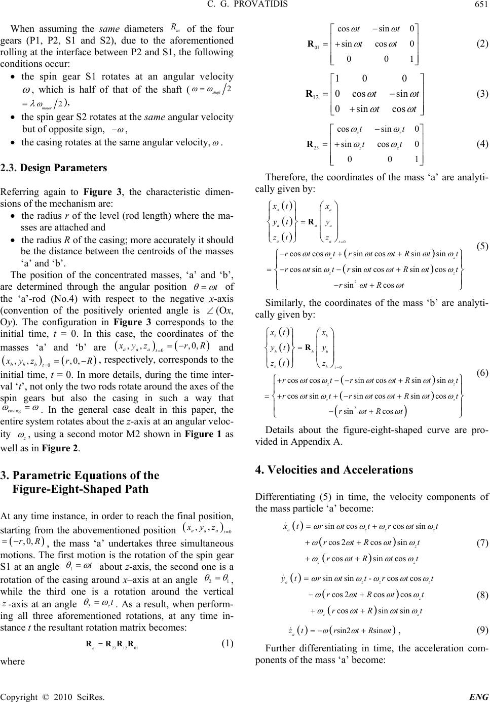 C. G. PROVATIDIS Copyright © 2010 SciRes. ENG 651 When assuming the same diameters m R of the four gears (P1, P2, S1 and S2), due to the aforementioned rolling at the interface between P2 and S1, the following conditions occur: the spin gear S1 rotates at an angular velocity , which is half of that of the shaft (2 shaft 2 motor ), the spin gear S2 rotates at the same angular velocity but of opposite sign, , the casing rotates at the same angular velocity, . 2.3. Design Parameters Referring again to Figure 3, the characteristic dimen- sions of the mechanism are: the radius r of the level (rod length) where the ma- sses are attached and the radius R of the casing; more accurately it should be the distance between the centroids of the masses ‘a’ and ‘b’. The position of the concentrated masses, ‘a’ and ‘b’, are determined through the angular position t of the ‘a’-rod (No.4) with respect to the negative x-axis (convention of the positively oriented angle is (Ox, Oy). The configuration in Figure 3 corresponds to the initial time, t = 0. In this case, the coordinates of the masses ‘a’ and ‘b’ are 0 ,, ,0, aaa t x yzr R and 0 ,, ,0, bbb t x yzrR , respectively, corresponds to the initial time, t = 0. In more details, during the time inter- val ‘t’, not only the two rods rotate around the axes of the spin gears but also the casing in such a way that casing . In the general case dealt in this paper, the entire system rotates about the z-axis at an angular veloc- ity z , using a second motor M2 shown in Figure 1 as well as in Figure 2. 3. Parametric Equations of the Figure-Eight-Shaped Path At any time instance, in order to reach the final position, starting from the abovementioned position 0 ,, aaa t xyz ,0,rR , the mass ‘a’ undertakes three simultaneous motions. The first motion is the rotation of the spin gear S1 at an angle 1t about z-axis, the second one is a rotation of the casing around x–axis at an angle 21 , while the third one is a rotation around the vertical z-axis at an angle 3 z t . As a result, when perform- ing all three aforementioned rotations, at any time in- stance t the resultant rotation matrix becomes: 23 1201aRRRR (1) where 01 cossin 0 sincos 0 001 tt tt R (2) 12 10 0 0cos sin 0sin cos tt tt R (3) 23 cossin 0 sin cos 0 001 zz zz tt tt R (4) Therefore, the coordinates of the mass ‘a’ are analyti- cally given by: 0 2 cos cossincossinsin cos sinsin cossincos sin cos aa aaa aa t zz zz xt x yt y zt z rt trttRtt rt trttRtt rtRt R (5) Similarly, the coordinates of the mass ‘b’ are analyti- cally given by: 0 2 coscossin cossinsin cos sinsincossincos sin cos bb bbb bb t zz zz xt x yt y ztz rt trttRtt rt trttRtt rtRt R (6) Details about the figure-eight-shaped curve are pro- vided in Appendix A. 4. Velocities and Accelerations Differentiating (5) in time, the velocity components of the mass particle ‘a’ become: sincoscos sin cos 2cossin cossincos azzz z zz x trttrt t rtRtt rtR t t (7) sin sin-cos cos cos 2coscos cossin sin azzz z zz y trt trtt rtRt t rtRt t (8) sin2 sin a z trtRt , (9) Further differentiating in time, the acceleration com- ponents of the mass ‘a’ become:  C. G. PROVATIDIS Copyright © 2010 SciRes. ENG 652 22 z 22 22 cos cos 4cos2 sinsin+2cos2+ coscos az zz z zz z xtr tt R rt r ttrtRt t (10) 22 2 2 +cossin+2sincos 2sin2 tsincos +2cos2+ cossin +cos+sintcos az zzz z zz zz ytrttrtt rRtt rtRt t rtRt (11) 22cos2cos a ztrtR t (12) Differentiating (6) in time, the velocity components of the mass ‘b’ are given by: sincoscos sin cos 2cossin cossin cos bzzz z zz x trttrtt rtRtt rtR t t (13) sin sincos cos cos 2coscos cossin sin bzzz z zz y trttrtt rtRt t rtRtt (14) sin2 sin b ztrtRt (15) By further differentiation in time, the acceleration components of the mass ‘b’ become: 2 2 2 2 cos cos2sin sin cos cos 4 sincossinsin 2cos2coscos sin cossinsin bzzz zz z zz zz x trttrtt rt t rt tRtt rtRt t rt tRtt (16) 22 2 2 cos sin 2sincos 2sin 2sincos 2cos 2cossin cossin cos bzz zz z z z zz ytr tt rt t rtRt t rtRtt rtRt t (17) 22cos2 +cos b ztrtR t (18) 5. Inertial Forces Based on the abovementioned kinematics, the compo- nents of the inertial force exerted on the mass ‘a’ can be calculated by: ,, xaa yaa zaa FmxFmyFmz (19) while those on the mass ‘b’: ,, xbb ybbzbb F mx Fmy Fmz (20) Substituting (10)-(12) into (19) and (16)-(18) into (20), the resultant force components are given by: 22 4sinsin24coscos2 xxaxb zz zz FF F ttt t mr (21) 22 4cossin24sincos2 yya yb zz zz FF Fmr ttt t (22) 2 4cos2 zza zb F FF mrt (23) Equation (23) depicts that: 1) the z-component of the resultant inertial force is proportional to the radius r, and 2) the maximum upward force z F (appearing at 0 ) is equal and opposite to the maximum downward (appearing at 12t ) value. It can be also noticed that the geometrical parameter R is not included in (21)-(23). Remark: When considering a second couple of equal masses ‘a'’ and ‘b'’ at a phase-difference 2 , it is trivial to verify that the corresponding forces x F and y F , which are given by (21) and (22) respectively, ideally cancel those of the first couple (a,b). 6. Elastic Deformation of Rods 6.1. Axial Forces In order to determine the axial component of the inertial force vector ,, T kxkykzk F FF kabF, at a certain mass, ‘a’ or ‘b’, it is necessary to consider the direction cosines along the rod axes, which are given by: / / / rxaa a ryaa a rzaa a nxxr nyyr nzzr (24) and / / / rxbb b rybb b rzbb b nxxr nyyr nzzr (25) where sinsin,sinsin sin cos,sin cos cos, cos azb z azbz ab x Rt txRt t yRttyRtt zR tz Rt (26) denote the coordinates of those ends of the rods that do not carry the concentrated masses.  C. G. PROVATIDIS Copyright © 2010 SciRes. ENG 653 6.2. Rod Deformation (Quasi-Static Analysis) Considering an instantaneous deformation of the elastic rod ‘a’ according to Hooke’s law (semi-static assump- tion), at every position the elongation of the rod that cor- responds to the mass particle ‘a’ is given by: ra a Fr rEA (27) and therefore the updated variable radius is given by: aa rr r (28) Similarly, for the rod that corresponds to the mass par- ticle mass ‘b’ it holds: rb b Fr rEA (29) and therefore the updated variable radius is given by: bb rr r (30) In order to simplify the subsequent analysis, without loss of generality we assume that 0R. In this case, the radial forces become: 222 23 cos1sin2cos ra zz F mrt tt (31) 222 23 cos1sin2cos rb zz F mrt tt (32) Also, the semi-static deformations become: 2222 2 3 cos1 sin 2cos az z m rrt t EA t (33) and therefore the updated variable radius is given by: 23 22 2 22 422cos cos 2 cos2 cos a z z m rr EA rt rt rt t (34) Similarly, for the rod that corresponds to the mass par- ticle mass ‘b’ it holds: 2222 2 3 cos1sin 2cos bz z m rrt t EA (35) and therefore the updated variable radius is given by: 22 2 22422 3 cos 2 cos2 cos2cos b zz m EA rr r t rt trt (36) Consequently, due to the change in the radii, z and b r, the updated vertical forces become: 2 2cos2 za aa Fmztmr t (37) 2 2cos2 zb bb Fmztmr t (38) 2 2cos2 zzazb ab F FFmrrt (39) Substituting (34) and (36) into (39), one obtains: 22 22 22 42 2cos4cos2 cos2cos z z rt EA m Fm tr rtt (40) Equation (40) can be split into two parts as follows: ,, z zrigid ztension FF F (41) with 2 ,4cos2 zrigid Fmrt (42) representing the vertical resultant force due to the ri- gid-body motion of the rods, and 22 , 22222 42 4cos2 2coscos2cos ztension z m Ft EA rtrtt (43) representing the contribution of the tension at the two elastic rods, which carry the mass particles ‘a’ and ‘b’. 7. Impulse The impulse caused by the vertical resultant force z F t is given by: 0 t zz ItF d (44) Integrating (40) over time, after manipulations the impulse (i.e., (44)) can be analytically expressed in clo- sed form, using one term for the rigid-body part and an- other for the tensile part, as follows: ,, z zrigid ztension II I (45) where ,2sin2 z rigid Imr (46) and 0246,sin 2sin 4sin 6 ztension ccc cI (47) with 2 222 0 2 222 2 2 222 4 2 22 6 93 8 4 24 z z z z t m cr EA m cr EA m cr EA m cr EA (48) Obviously, the harmonics (sin2, sin 4,sin 6 ) in (47)  C. G. PROVATIDIS Copyright © 2010 SciRes. ENG 654 lead to zero values every 180, 90 and 60 degrees, respec- tively, thus not practically contributing to the propulsion. Concerning particularly the second harmonic (sin 2 ), not only the elastic part of the impulse vanishes every 180 degrees, but also that caused by the rigid-body mo- tion (cf. Equation (46)). However, in addition to the three harmonic terms, (47) includes also the term 0 ct , which increases linearly with the time t. The analytical expression of the term 0 c in (48) depicts that for a given angular frequency and given elasticity properties of the two rods, the value of the net impulse is fully con- trolled by the angular frequency z . 8. A Preliminary Experimental Result The prototype device weights approximately 22 kg in- cluding all its structural members and the electric motors. For reasons of functionality, the elastic bars (member No. 4 and member No. 5 in Figure 2) were manufactured adequately thin, of 5.5 mm diameter and of 200 mm len- gth, made of steel. Each lumped mass was taken appro- ximately equal to 20 grams. The prototype device was put in the center of the horizontal platform of an elec- tronic scale, which was equipped by four identical strain- gages at its four corners. The mean average of these four sensors was shown on a digital display, with an accuracy of ± 10 gr. The experimental validation was a very difficult task, mainly due to the high angular velocities required to ov- ercome the gyroscopic phenomena appearing in the pro- totype and the high bending occurring in the particular choice of thin cylindrical bars. Nevertheless, even for the abovementioned small masses, and even for the very slow angular velocities (100 300 rpm) that were al- lowed so as to avoid collision (of the members No.4 and No.5 on the horizontal shaft No.2, shown in Figure 2), the resultant impulse obtains a nonzero value. Clearly, for a time-interval of 124 seconds in which 618 meas- urements were automatically recorded as shown in Fig- ure 4, the relative difference of the sum of the negative values with respect to the sum of the positive values was found about 11.6%, a fact that sustains the findings of the abovementioned theoretical analysis. 9. Discussion It is remarkable that the findings of this paper are in con- sistency with previous experimental results (8% weight- reduction) related to ideally rigid gyroscopes [16]. Since the proposed device is essentially a flexible (elastic) gy- roscope of which the masses operate in a hemisphere, it is believed that similar accurate experiments with th- ose of [16] should be performed for the current device. Figure 4. A digital record of the ground reaction (in dN or kg-force), for a time interval of approximately 2 minutes, using two lumped masses each of 20 gr and low angular velocities: approximately = 100 rpm and z = 320 rpm. The amplitude of the ground force is close to 0.2 kg-force (i.e., 0.2 dN, equivalently, 2 N). It is also believed that the proposed idea is a mechanical alternative to older relativistic thoughts of 1960s, which have recently revived [17]. In addition to the experimental shortcomings men- tioned in Section 8, the weaknesses of the approximate model presented in this study are as follows: Only the action of the concentrated masses has been considered, while the moment of inertia of the rods has been omitted. The axial deformation of the rods has been assumed to coincide with that of static conditions immedi- ately imposed at every time instance, while a more accurate semi-analytical approach had to consider dynamic response caused by longitudinal and trans- verse traveling elastic waves along the rods. The influence of the bending deformation of the el- astic bars has not been considered. The angular velocities and z have been con- sidered to be constant while an accurate simulation model would require the dynamic modeling of the motors themselves or/and the use of power-to-an- gular velocity curves [18,19]. For the particular setup of this paper, at 2,3 2 the masses ‘a’ and ‘b’ are found at the point of intersection I 0, 0, R r. This ‘collision’ could be theoretically avoided considering one mass being of male and the other of female type. Obvi- ously, in the general case where 0R this short- coming is easily overcome but this selection leads to more complicated analytical expressions that do not offer further insight or any other essential ad- vantages. Concerning the mathematical analysis of this work, of course a more accurate analysis has to be performed on  C. G. PROVATIDIS Copyright © 2010 SciRes. ENG 655 the basis of a finite element elastodynamic model of the entire structure in which not only tension but also bend- ing and torsion will be automatically considered. A spe- cial feature of such an analysis is the dependence of the inertial forces on the radius, which is not a-prio ri known. Furthermore, concerning the experimental part of this work, it is worth-mentioning that not in all cases the ex- periments were of the same quality as that presented in Figure 4. In general, in order to achieve a remarkable net impulse, a proper synchronization between the two an- gular velocities, and z , is required. In order to in- crease the magnitude of the net impulse, one could in- crease either the angular velocities or the magnitude of the lumped masses. In both cases the high bending in- volved requires thick rods (high diameters) as well as motors of high electric power. Therefore, due to the lim- ited power capacity and, since the overall mechanical strength of the experimental setup could not be improved we were forced to stay with preliminary measurements only. Of course, a future study should consider an en- tirely different experimental setup. Summarizing, the aforementioned advanced elastody- namic model has also to be compared with high precision experiments on a well-designed experimental device, a fact that presupposes high technical skills and high-tech premises, probably within an advanced industrial envi- ronment. 10. Conclusions This work contributes to the field of inertial propulsion, proposing a new concept for the production of net im- pulse through rotating masses. In the beginning, it was shown that when a lumped mass moves along a circum- ference, it repeats its position every 360 degrees, thus its initial linear momentum is repeated and no net impulse is finally produced for a whole revolution; this case corre- sponds to the notorious ‘Dean drive’. Then, it was theor- etically shown that when two lumped masses move along a specific figure-eight-shaped path at a phase difference of 180 degrees, in such a way that the latter path lays on the surface of a hemisphere that additionally spins about its axis of symmetry, the involved inertial forces lead to a non-vanishing net impulse. Intuitively, this claim is true because when the ratio of the spinning angular velocity over the first one (formation of the figure-eight-shaped path) is not an integer number, every mass does not re- peat its initial position; in other words, when the mass completes the figure-eight-shaped path (every 360 de- grees), the linear momentum has a different value that what it had at the initial position. In terms of combined structural mechanics and kinematics, every mass is con- nected to the center of the hemisphere through an elastic rod that is imposed to highly variable tensile deformation. This finding implies a variable radius of the hemisphere and is decisive to produce net impulse towards the axis of symmetry of the hemisphere. In addition to the theo- retical findings, for purposes of demonstration and vali- dation, a prototype mechanical device, capable of pro- ducing the two aforementioned rotations, was manufac- tured and fully described in this paper. Although the need for more realistic experimental tests has been dis- cussed, preliminary measurements are in consistency with the proposed theory and sustain the production of net impulse using rotating masses. 11. References [1] H. Yoshikawa, T. Kagiwada, H. Harada and M. Mimura, “Improvement of Propulsion Mechanism Based on the Inertial Force,” In: F. Kimura and K. Horio, Eds., To- wards Synthesis of Micro-/Nano-Systems, Springer, Lon- don, 2007, pp. 333-334. [2] J. M. Gilbert, “Gyrobot: Control of Multiple Degree of Freedom Underactuated Mechanisms Using a Gyrating Link and Cyclic Braking,” IEEE Transactions on Robot- ics, Vol. 23, No. 4, 2007, pp. 822-827. [3] P. R. Ouyang, Q. Li and W. J. Zhang, “Integrated Design of Robotic Mechanisms for Force Balancing and Trajec- tory Tracking,” Mechatronics, Vol. 13, No. 8-9, October 2003, pp. 887-905. [4] N. L. Dean, “System for Converting Rotary Motion into Unidirectional Motion,” US Patent 2886976, 19 May 1959. [5] I. I. Blekhman, “Synchronization in Science and Tech- nology,” ASME Press, New York, 1988. [6] I. I. Blekhman, P. S. Landa and M. G. Rozenblum, “Synchronization and Chaotization in Interacting Dy- namical Systems,” Applied Mechanics Reviews, Vol. 48, No. 11, November 1995, pp. 733-752. [7] I. I. Blekhman, A. L. Fradkov, H. Nijmeijer and A. Yu. Pogromsky, “On Self-Synchronization and Controlled Synchronization,” Systems and Control Letters, Vol. 31, No. 5, October 1997, pp. 299-305. [8] G. Y. Stepanov, “Why is it Impossible to Have ‘Dean’s Apparatus’?” Journal Priroda (in Russian), Vol. 7, 1963, pp. 85-91. [9] I. I. Blekhman, “Vibrational Mechanics: Nonlinear Dy- namic Effects, General Approach, Applications,” World Scientific, Singapore, 2000. [10] M. G. Millis and N. E. Thomas, “Responding to Me- chanical Antigravity,” NASA/TM-2006-214390, AIAA- 2006-4913, December 2006. http://gltrs.grc.nasa.gov/re- ports/2006/TM-2006-214390.pdf [11] M. G. Millis, “Assessing Potential Propulsion Break- throughs,” In: E. Belbruno, Ed., Annals of the New York Academy of Sciences, Vol. 1065, New York, December 2005, pp. 441-461. [12] C. G. Provatidis, “Some Issues on Inertia Propulsion Mechanisms Using Two Contra-Rotating Masses,” The- ory of Mechanisms and Machines, Vol. 8, No. 1, April  C. G. PROVATIDIS Copyright © 2010 SciRes. ENG 656 2010, pp. 34-41. [13] C. G. Provatidis and V. Th. Tsiriggakis, “A New Kine- matics Theory in Physics and Presentation of a Device for Gravity Studies,” Proceedings 9th International Scien- tific-Practical Conference on Research, Development and Applications of High Technologies in Industry, A. P. Kudinov, Ed., Vol. 1, St. Petersburg, April 2010, pp. 386- 393. [14] C. G. Provatidis and V. Th. Tsiriggakis, “A New Concept and Design Aspects of an ‘Antigravity’ Propulsion Mechanism Based on Inertial Forces,” Proceedings 46th AIAA/ASME/SAE/ASEE Joint Propulsion Conference & Exhibit, Nashville, July 2010. [15] C. G. Provatidis, “A Novel Mechanism to Produce Fig- ure-Eight-Shaped Closed Curves in the Three-Dimen- sional Space,” In: D. Tsahalis, Ed., Proceedings of 3rd International Conference on Experiments/Process/System Modeling/Simulation & Optimization, Athens, July 2009. [16] R. Wayte, “The Phenomenon of Weight-Reduction of a Spinning Wheel,” Meccanica, Vol. 42, No. 4, August 2007, pp. 359-364. [17] M. Tajmar, “Homopolar Artificial Gravity Generator Based on Frame-Dragging,” Acta Astronautica, Vol. 66, No. 9-10, May-June 2010, pp. 1297-1301. [18] V. O. Kononenko “Vibrating Systems with a Limited Power Supply,” Iliffe Books Ltd, London, 1969. [19] A. H. Nayfeh and D. T. Mook “Nonlinear Oscillations,” John Wiley & Sons, Inc., New York, 1979.  C. G. PROVATIDIS Copyright © 2010 SciRes. ENG 657 APPENDIX A Remarks concerning the figure-eight-shaped curve For the purpose of completeness, details are provided here for the figure-eight-shaped curve. First, in the absence of the spinning motion, i.e., when 0 z , a careful inspection of (5) and (6) reveals that: 1) At the initial time instance (0t), in fact the rods obtain their horizontal position parallel to x-axis, i.e., ‘a’ on the left and ‘b’ on the right side. 2) At the time instance given by 2t , both masses obtain their vertical position. 3) At the time instance given by t , the masses mutu- ally interchange their (horizontal) position. 4) At the time instance given by 32t , the masses are again found at their vertical position. 5) At the time instance given by 2t , the masses obtain their initial (horizontal) position, and so on. 6) Therefore, the distance between the two masses varies from the minimum 2 R (vertical position) to the maxi- mum value 22 2rR (horizontal position). 7) Both mass particles, ‘a’ and ‘b’, share a common path. This happens because when putting ab tt t in Equation (5), then it becomes identical with Equation (6). In other words, the masses ‘a’ and ‘b’ move on the same path and appear a constant phase difference of 180 degrees, thus they are mutually interchanged. 8) During the first 90 degrees (1 0a ), the mass ‘a’ draws the blue line while ‘b’ draws the red line of the common path (Figure 5(a)). In the next 90 degrees the situation is reversed, so as the mass ‘a’ follows the read and the mass ‘b’ follows the blue line. 9) The common path intersects itself at the unique point I ,0, R r, which corresponds to 12 a or 1a 32 , and so on. 10) All points of the abovementioned path belong to a sphere of radius, i.e.: 222 2222 aa abbb sphere x yzxyz r , with 22 sphere rrR Second, in the case of a non-vanishing spinning angular ve- locity (0 z ), the lumped masses do not generally follow the same path, as clearly shown in Figures 5(b)-5(f), particularly when the ratio z of the angular velocities is not an integer number. Figure 5. Perspective view of the paths drawn by the lumped masses (r = 80 mm, R = 0), which are produced at different synchronizations (ratio of angular velocities, z ): (a) ratio = 0, (b) ratio = 0.5, (c) ratio = 1.0, (d) ratio = 2.0, (e) ratio = 3.0 and (f) ratio = 3.5. In all cases, the blue and red lines correspond to the masses ‘a’ and ‘b’ (shown in Figure 2), respectively. The cases (a) and (d) are shown for the first 180 degrees (0t ) so as to avoid overlap- ping, while the rest cases for the first 720 degrees (04t ). |