Paper Menu >>
Journal Menu >>
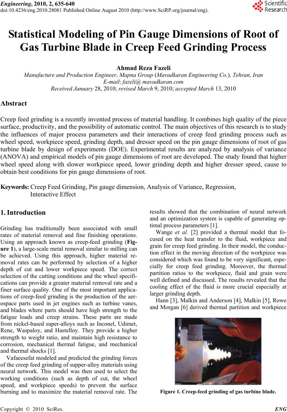 Engineering, 2010, 2, 635-640 doi:10.4236/eng.2010.28081 Published Online August 2010 (http://www.SciRP.org/journal/eng). Copyright © 2010 SciRes. ENG Statistical Modeling of Pin Gauge Dimensions of Root of Gas Turbine Blade in Creep Feed Grinding Process Ahmad Reza Fazeli Manufacture and Production Engineer, Mapna Group (Mavadkaran Engineering Co.), Tehran, Iran E-mail: fazeli@ mavadkaran.com Received January 28, 2010; revised March 9, 2010; accepted March 13, 2010 Abstract Creep feed grinding is a recently invented process of material handling. It combines high quality of the piece surface, productivity, and the possibility of automatic control. The main objectives of this research is to study the influences of major process parameters and their interactions of creep feed grinding process such as wheel speed, workpiece speed, grinding depth, and dresser speed on the pin gauge dimensions of root of gas turbine blade by design of experiments (DOE). Experimental results are analyzed by analysis of variance (ANOVA) and empirical models of pin gauge dimensions of root are developed. The study found that higher wheel speed along with slower workpiece speed, lower grinding depth and higher dresser speed, cause to obtain best conditions for pin gauge dimensions of root. Keywords: Creep Feed Grinding, Pin gauge dimension, Analysis of Variance, Regression, Interactive Effect 1. Introduction Grinding has traditionally been associated with small rates of material removal and fine finishing operations. Using an approach known as creep-feed grinding (Fig- ure 1), a large-scale metal removal similar to milling can be achieved. Using this approach, higher material re- moval rates can be performed by selection of a higher depth of cut and lower workpiece speed. The correct selection of the cutting conditions and the wheel specifi- cations can provide a greater material removal rate and a finer surface quality. One of the most important applica- tions of creep-feed grinding is the production of the aer- ospace parts used in jet engines such as turbine vanes, and blades where parts should have high strength to the fatigue loads and creep strains. These parts are made from nickel-based super-alloys such as Inconel, Udimet, Rene, Waspaloy, and Hastelloy. They provide a higher strength to weight ratio, and maintain high resistance to corrosion, mechanical thermal fatigue, and mechanical and thermal shocks [1]. Vafaeesefat modeled and predicted the grinding forces of the creep feed grinding of supper-alloy materials using neural network. This model was then used to select the working conditions (such as depth of cut, the wheel speed, and workpiece speeds) to prevent the surface burning and to maximize the material removal rate. The results showed that the combination of neural network and an optimization system is capable of generating op- timal process parameters [1]. Wange et al. [2] provided a thermal model that fo- cused on the heat transfer to the fluid, workpiece and grain for creep feed grinding. In their model, the conduc- tion effect in the moving direction of the workpiece was considered which was found to be very significant, espe- cially for creep feed grinding. Moreover, the thermal partition ratios to the workpiece, fluid and grain were well defined and discussed. The results revealed that the cooling effect of the fluid is more crucial especially at larger grinding depth. Hann [3], Malkin and Anderson [4], Malkin [5], Rowe and Morgan [6] derived thermal partition and workpiece Figure 1. Creep-feed grinding of gas turbine blade. 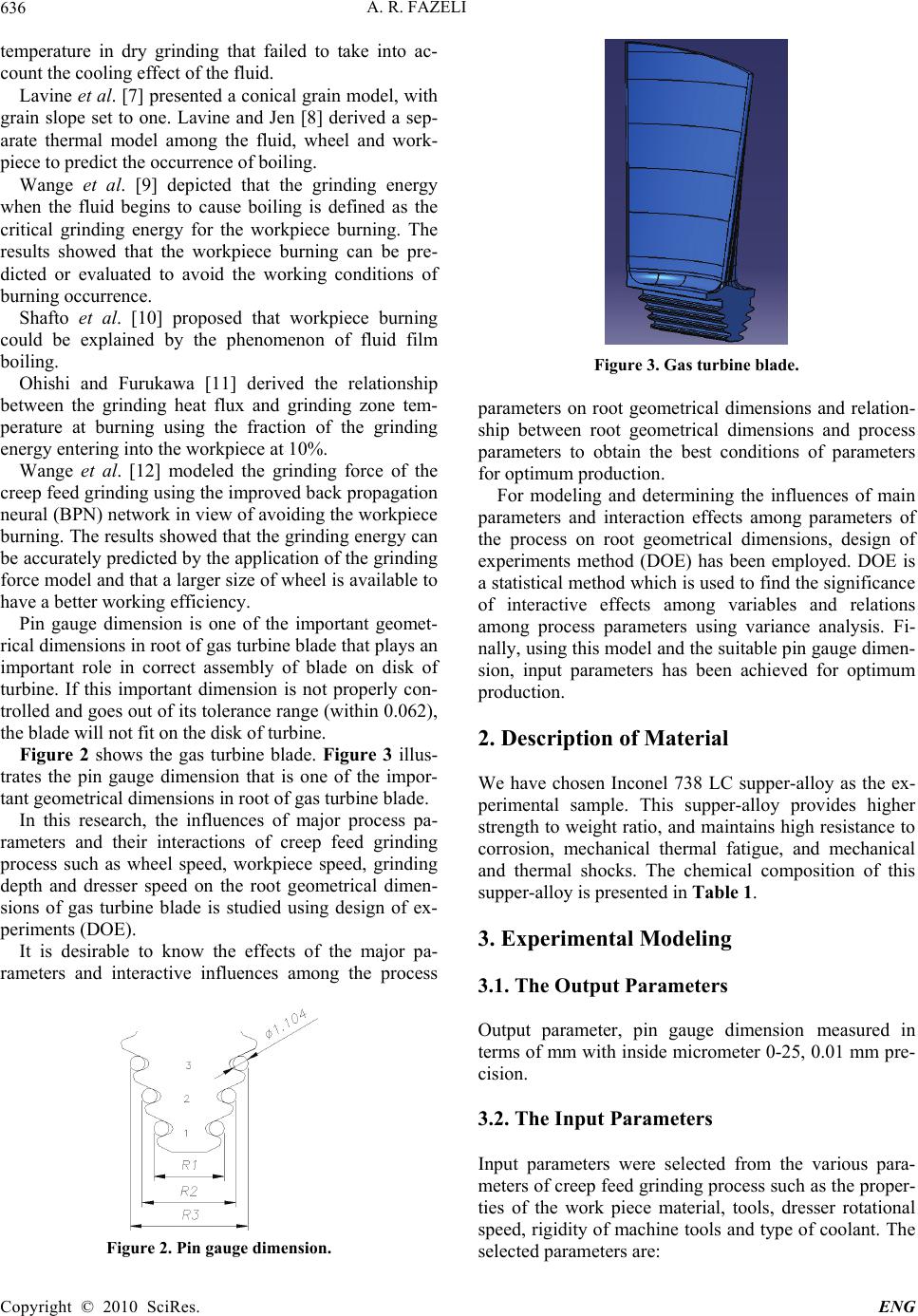 A. R. FAZELI Copyright © 2010 SciRes. ENG 636 temperature in dry grinding that failed to take into ac- count the cooling effect of the fluid. Lavine et al. [7] presented a conical grain model, with grain slope set to one. Lavine and Jen [8] derived a sep- arate thermal model among the fluid, wheel and work- piece to predict the occurrence of boiling. Wange et al. [9] depicted that the grinding energy when the fluid begins to cause boiling is defined as the critical grinding energy for the workpiece burning. The results showed that the workpiece burning can be pre- dicted or evaluated to avoid the working conditions of burning occurrence. Shafto et al. [10] proposed that workpiece burning could be explained by the phenomenon of fluid film boiling. Ohishi and Furukawa [11] derived the relationship between the grinding heat flux and grinding zone tem- perature at burning using the fraction of the grinding energy entering into the workpiece at 10%. Wange et al. [12] modeled the grinding force of the creep feed grinding using the improved back propagation neural (BPN) network in view of avoiding the workpiece burning. The results showed that the grinding energy can be accurately predicted by the application of the grinding force model and that a larger size of wheel is available to have a better working efficiency. Pin gauge dimension is one of the important geomet- rical dimensions in root of gas turbine blade that plays an important role in correct assembly of blade on disk of turbine. If this important dimension is not properly con- trolled and goes out of its tolerance range (within 0.062), the blade will not fit on the disk of turbine. Figure 2 shows the gas turbine blade. Figure 3 illus- trates the pin gauge dimension that is one of the impor- tant geometrical dimensions in root of gas turbine blade. In this research, the influences of major process pa- rameters and their interactions of creep feed grinding process such as wheel speed, workpiece speed, grinding depth and dresser speed on the root geometrical dimen- sions of gas turbine blade is studied using design of ex- periments (DOE). It is desirable to know the effects of the major pa- rameters and interactive influences among the process Figure 2. Pin gauge dimension. Figure 3. Gas turbine blade. parameters on root geometrical dimensions and relation- ship between root geometrical dimensions and process parameters to obtain the best conditions of parameters for optimum production. For modeling and determining the influences of main parameters and interaction effects among parameters of the process on root geometrical dimensions, design of experiments method (DOE) has been employed. DOE is a statistical method which is used to find the significance of interactive effects among variables and relations among process parameters using variance analysis. Fi- nally, using this model and the suitable pin gauge dimen- sion, input parameters has been achieved for optimum production. 2. Description of Material We have chosen Inconel 738 LC supper-alloy as the ex- perimental sample. This supper-alloy provides higher strength to weight ratio, and maintains high resistance to corrosion, mechanical thermal fatigue, and mechanical and thermal shocks. The chemical composition of this supper-alloy is presented in Table 1. 3. Experimental Modeling 3.1. The Output Parameters Output parameter, pin gauge dimension measured in terms of mm with inside micrometer 0-25, 0.01 mm pre- cision. 3.2. The Input Parameters Input parameters were selected from the various para- meters of creep feed grinding process such as the proper- ties of the work piece material, tools, dresser rotational speed, rigidity of machine tools and type of coolant. The selected parameters are: 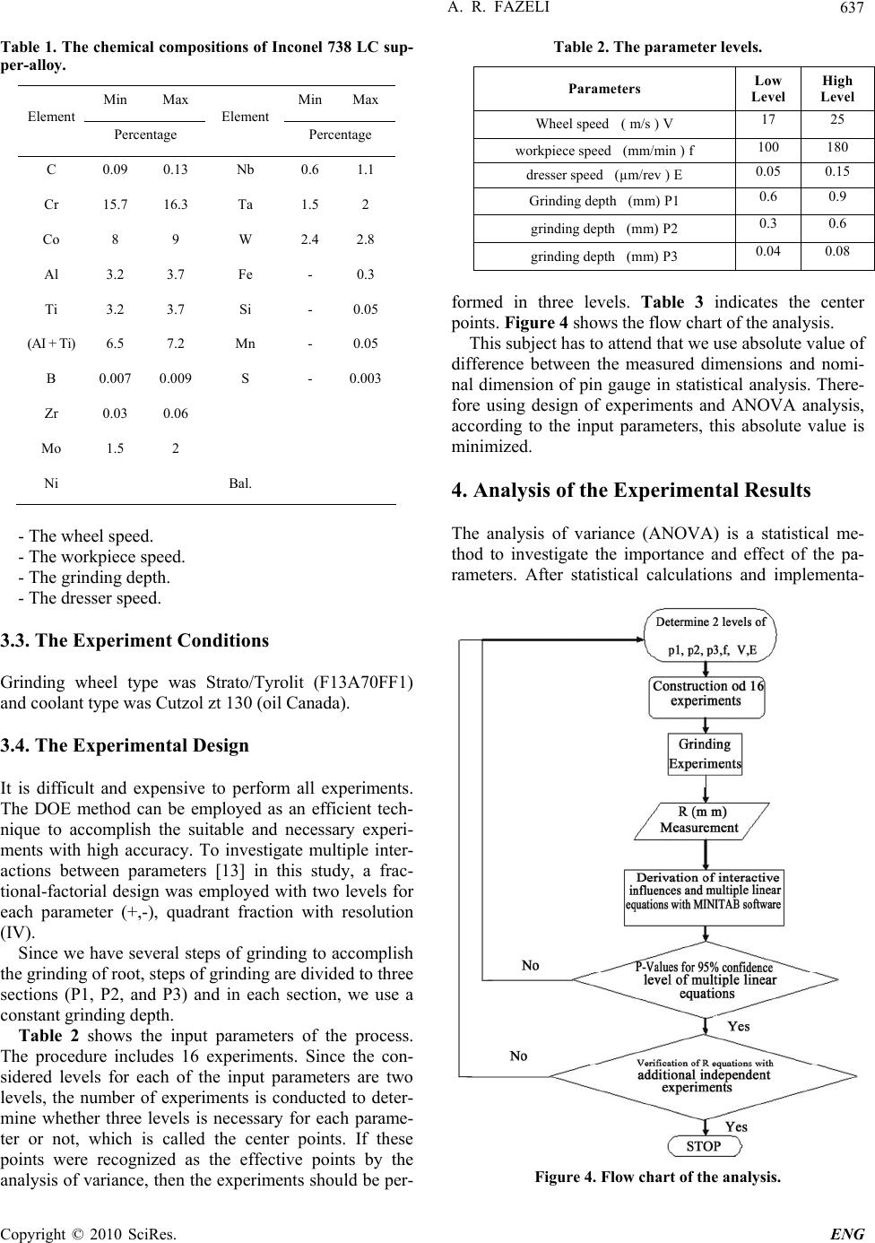 A. R. FAZELI Copyright © 2010 SciRes. ENG 637 Table 1. The chemical compositions of Inconel 738 LC sup- per-alloy. Min Max Min Max Element Percentage Element Percentage C 0.09 0.13 Nb 0.6 1.1 Cr 15.7 16.3 Ta 1.5 2 Co 8 9 W 2.4 2.8 Al 3.2 3.7 Fe - 0.3 Ti 3.2 3.7 Si - 0.05 (AI + Ti) 6.5 7.2 Mn - 0.05 B 0.007 0.009 S - 0.003 Zr 0.03 0.06 Mo 1.5 2 Ni Bal. - The wheel speed. - The workpiece speed. - The grinding depth. - The dresser speed. 3.3. The Experiment Conditions Grinding wheel type was Strato/Tyrolit (F13A70FF1) and coolant type was Cutzol zt 130 (oil Canada). 3.4. The Experimental Design It is difficult and expensive to perform all experiments. The DOE method can be employed as an efficient tech- nique to accomplish the suitable and necessary experi- ments with high accuracy. To investigate multiple inter- actions between parameters [13] in this study, a frac- tional-factorial design was employed with two levels for each parameter (+,-), quadrant fraction with resolution (IV). Since we have several steps of grinding to accomplish the grinding of root, steps of grinding are divided to three sections (P1, P2, and P3) and in each section, we use a constant grinding depth. Table 2 shows the input parameters of the process. The procedure includes 16 experiments. Since the con- sidered levels for each of the input parameters are two levels, the number of experiments is conducted to deter- mine whether three levels is necessary for each parame- ter or not, which is called the center points. If these points were recognized as the effective points by the analysis of variance, then the experiments should be per- Table 2. The parameter levels. High Level Low Level Parameters 25 17 Wheel speed ( m/s ) V 180 100 workpiece speed (mm/min ) f 0.15 0.05 dresser speed (µm/rev ) E 0.9 0.6 Grinding depth (mm) P1 0.6 0.3 grinding depth (mm) P2 0.08 0.04 grinding depth (mm) P3 formed in three levels. Table 3 indicates the center points. Figure 4 shows the flow chart of the analysis. This subject has to attend that we use absolute value of difference between the measured dimensions and nomi- nal dimension of pin gauge in statistical analysis. There- fore using design of experiments and ANOVA analysis, according to the input parameters, this absolute value is minimized. 4. Analysis of the Experimental Results The analysis of variance (ANOVA) is a statistical me- thod to investigate the importance and effect of the pa- rameters. After statistical calculations and implementa- Figure 4. Flow chart of the analysis. 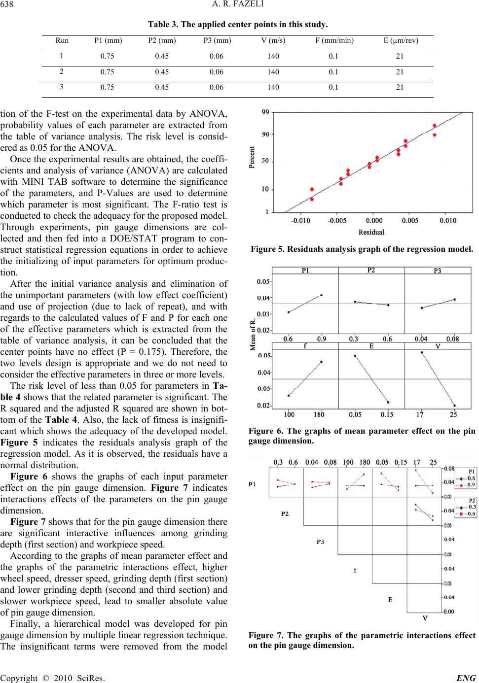 A. R. FAZELI Copyright © 2010 SciRes. ENG 638 Table 3. The applied center points in this study. E (µm/rev) F (mm/min) V (m/s) P3 (mm) P2 (mm) P1 (mm) Run 21 0.1 140 0.06 0.45 0.75 1 21 0.1 140 0.06 0.45 0.75 2 21 0.1 140 0.06 0.45 0.75 3 tion of the F-test on the experimental data by ANOVA, probability values of each parameter are extracted from the table of variance analysis. The risk level is consid- ered as 0.05 for the ANOVA. Once the experimental results are obtained, the coeffi- cients and analysis of variance (ANOVA) are calculated with MINI TAB software to determine the significance of the parameters, and P-Values are used to determine which parameter is most significant. The F-ratio test is conducted to check the adequacy for the proposed model. Through experiments, pin gauge dimensions are col- lected and then fed into a DOE/STAT program to con- struct statistical regression equations in order to achieve the initializing of input parameters for optimum produc- tion. After the initial variance analysis and elimination of the unimportant parameters (with low effect coefficient) and use of projection (due to lack of repeat), and with regards to the calculated values of F and P for each one of the effective parameters which is extracted from the table of variance analysis, it can be concluded that the center points have no effect (P = 0.175). Therefore, the two levels design is appropriate and we do not need to consider the effective parameters in three or more levels. The risk level of less than 0.05 for parameters in Ta- ble 4 shows that the related parameter is significant. The R squared and the adjusted R squared are shown in bot- tom of the Table 4. Also, the lack of fitness is insignifi- cant which shows the adequacy of the developed model. Figure 5 indicates the residuals analysis graph of the regression model. As it is observed, the residuals have a normal distribution. Figure 6 shows the graphs of each input parameter effect on the pin gauge dimension. Figure 7 indicates interactions effects of the parameters on the pin gauge dimension. Figure 7 shows that for the pin gauge dimension there are significant interactive influences among grinding depth (first section) and workpiece speed. According to the graphs of mean parameter effect and the graphs of the parametric interactions effect, higher wheel speed, dresser speed, grinding depth (first section) and lower grinding depth (second and third section) and slower workpiece speed, lead to smaller absolute value of pin gauge dimension. Finally, a hierarchical model was developed for pin gauge dimension by multiple linear regression technique. The insignificant terms were removed from the model Figure 5. Residuals analysis graph of the regression model. Figure 6. The graphs of mean parameter effect on the pin gauge dimension. Figure 7. The graphs of the parametric interactions effect on the pin gauge dimension.  A. R. FAZELI Copyright © 2010 SciRes. ENG 639 Table 4: The variance analysis (ANOVA) for the pin gauge dimension of root of blade Parameters Coefficient P-Value Constant P1 P2 P3 f E V P1xP2 P1xP3 P1xf P1xE P1xV -0.3 0.683 -0.067 1 -0.001 0.74 0.012 -0.222 -1.166 0.001 -1.366 -0.028 0.001 0.174 0. 758 0.460 0.04 0.017 0.012 0.19 0.322 0.032 0.04 0.01 R-Sq = %97.89 R-Sq(adj) = %89.43 and the final models were developed with significant terms which were determined by ANOVA Equation (1) for pin gauge dimension. 10.30.683(P1)0.067(P2)P30.001(f ) 0.74(E)0.012(V)0.222(P1P2)1.166(P1 P3) 0.001(P1f )1.366(P1E) - 0.028(P1V) R (1) 20.330.738(P1)0.56(P2)0.075P30.0002(f ) 0.21(E)0.014(V)1.105(P1 P2)0.031(P1V) 0.019(P2 V) R (2) 30.130.453(P1)0.033(P2)0.0005(f ) 0.255(E)0.006(V)0.683(P1E)0.272(P1P2) 0.0008(P1f )0.11(P2V) -0.018(P1V) R (3) 5. Discussion Figure 8 summarizes the wheel speed on the pin gauge dimension at grinding depth (first section). The results show that an increase of wheel speed combined with the increase of grinding depth (first section), produces small absolute value of pin gauge dimension. Figure 9 shows the effect of workpiece speed on the pin gauge dimension at grinding depth (first section). The results show that a decrease of workpiece speed combined with the increase of grinding depth (first sec- tion) produces small absolute value of pin gauge dimen- sion. Figure 10 summarizes the dresser speed on the pin gauge dimension at grinding depth (first section). The results show that an increase of dresser speed combined with the increase of grinding depth (first section), pro- duces small absolute value of difference between the measured dimensions and nominal dimension of pin gauge dimension. Reasonably, with higher wheel speed, grinding depth (first section) and slower workpiece speed, machining forces apply equally on the other side of root. Therefore Figure 8. Effect of the wheel speed on the pin gauge dimen- sion at grinding depth (first section). Figure 9. Effects of the workpiece speed on the pin gauge dimension at grinding depth (first section). Figure 10. Effects of the dresser speed on the pin gauge dimension at grinding depth (first section). Grinding depth (mm)  A. R. FAZELI Copyright © 2010 SciRes. ENG 640 absolute value of pin gauge dimension decreases. 6. Conclusions In this study, the creep feed grinding process has been optimized by selection of significant input parameters including the wheel speed, dresser speed, grinding depth and slower workpiece speed. Finally, by means of ANOVA, the main effects of the input parameters and their interactions on the pin gauge dimension were de- termined. Based on the statistical analysis of the experi- mental data the following conclusions can be obtained. 1) According to the variance analysis and the effect of interactions between the input parameters, it can be con- cluded that with higher wheel speed, dresser speed, grinding depth (first section) and lower grinding depth (second and third section) and slower workpiece speed, the pin gauge dimension decreases and as a result the pin gauge dimension reaches a suitable level. 2) In the creep feed grinding process center points have insignificant effects on the pin gauge dimension. It means that the process can be modeled with two levels for each input parameters. 3) Finally, with the large number of effective parame- ters in the creep feed grinding process, consideration of the creep feed grinding process through the design of experiments is shown to be the efficient method for achieving the acceptable results. 7. References [1] A. Vafaeesefat, “Optimum Creep Feed Grinding Process Conditions for Rene 80 Supper Alloy Using Neural Net- work,” International Journal of Precision Engineering and Manufacturing, Vol. 10, No. 3, 2009, pp. 5-11. [2] S.-B. Wang and H.-S. Kou, “Selections of Working Con- ditions for Creep Feed Grinding. Part (I)–Thermal Parti- tion ratios,” International Journal of Advanced Manu- facturing Technology, Vol. 23, No. 6, 2004, pp. 700-706. [3] R. S. Hahn, “on the Nature of the Grinding Process,” In: Proceedings of 3rd MTDR Conference, London, 1963, pp. 129-154. [4] S. Malkin and R. B. Andersson, “Thermal Analysis of the Grinding. Part I: Energy Partition,” Journal of Industrial Engineering, Vol. 96, 1974, pp. 1177-1183. [5] S. Malkin, “Thermal Analysis of the Grinding. Part II- surface Temperature and Workpiece Burn,” Journal of Engineering for Industry, Vol. 96, 1974, pp. 1184-1191. [6] W. B. Rowe and M. N. Morgan, “A Simplified Approach to Control of Thermal Damage in Grinding,” Annals CIRP, Vol. 45, No. 1, 1996, pp. 299-302. [7] S. Lavine, S. Malkin and T. C. Jen, “Thermal Aspects of Grinding with CBN Wheels,” Annals CIRP, Vol. 38, No. 1, 1989, pp. 557-560. [8] S. Lavine and T. C. Jen, “Coupled Heat Transfer to Workpiece, Wheel, and Fluid in Grinding, and the Oc- currence of Workpiece Burn,” International Journal of Heat Mass Transfer, Vol. 34, No. 45, 1991, pp. 983-992. [9] S.-B. Wang and H.-S. Kou, “Selections of Working Con- ditions for Creep Feed Grinding. Part (II): Workpiece Temperature and Critical Grinding Energy for Burning,” International Journal of Advanced Manufacturing Tech- nology, Vol. 28, No. 1-2, 2006, pp. 38-44. [10] G. R. Shafto, T. D. Howes and C. Andrew, “Thermal Aspects of Creep Feed Grinding,” 16th Machine Tool Design Research Conference, Manchester, England, 1975, pp. 31-37. [11] S. Ohishi and Y. Furukawa, “Analysis of Workpiece Temperature and Grinding Burn in Creep Feed Grind- ing,” Bull JSME, Vol. 28, No. 242, 1985, pp. 1775-1781. [12] S.-B. Wang and H.-S. Kou, “Selections of Working Con- ditions for Creep Feed Grinding. Part (III): Avoidance of the Workpiece Burning by Using Improved BP Neural Network,” International Journal of Advanced Manufac- turing Technology, Vol. 28, No. 1, 2006, pp. 31-37. [13] C. Montgomery, “Design of Experimental & Statistical Modeling,” McGraw Hill, Inc., New York, 2005. |