Paper Menu >>
Journal Menu >>
 Engineering, 2010, 2, 608-616 doi:10.4236/eng.2010.28078 Published Online August 2010 (http://www.SciRP.org/journal/eng). Copyright © 2010 SciRes. ENG Highly Nonlinear Bending-Insensitive Birefringent Photonic Crystal Fibres Huseyin Ademgil, Shyqyri Haxha, Fathi AbdelMalek Broadband and wireless communication group, School of Engineering and Digital Arts, University of Kent, Canterbury, UK E-mail: ademgil@hotmail.com Received May 20, 2010; revised July 21, 2010; accepted July 23, 2010 Abstract Highly nonlinear birefringent Photonic Crystal Fibre (PCF) that exhibits low losses and small effective mode area across a wide wavelength range has been presented. The effects of angular orientation on bending losses of the proposed PCFs have been thoroughly investigated by employing a full vectorial finite element method (FEM). It has been demonstrated that it is possible to design a bending-insensitive nonlinear PCF with a bi- refringence in the order of 10-2 and a nonlinear coefficient of 49 W-1km-1 at the wavelength of 1.55 μm. Also, significant improvements on key propagation characteristics of the proposed PCFs have been demonstrated by carefully altering the desired air hole diameters and the hole-to-hole spacing. It is demonstrated that two zero dispersion wavelengths can be achieved by the proposed design. Keywords: Nonlinear Coefficient, Effective Mode Area, Confinement Loss and Birefringence 1. Introduction Photonic Crystal Fibers consisting of a central defect region in a regular lattice of air holes have attracted sig- nificant research attention. These fibers provide extra degrees of freedom in manipulating optical properties [1-2]. PCFs can be divided into two categories according to the mechanism used to guide the light: photonic-band- gap (PBG) guidance and effective index guidance. The PBG fibers use a perfectly periodic structure exhibiting a PBG effect of the crystal lattice at the operating wave- length to guide light in a low-index core region. In PBG fibres, the core can be created from the lower refractive index material, which could be solid glass or a large air hole (in the case of an air-glass PCF) [3-5]. On the other hand, the effective index-guiding PCFs rely on total in- ternal reflection (TIR) to confine light in the region of missing air hole forming a central core. The presence of air holes decreases the effective index of the cladding, making light guidance possible by TIR. This guiding method is more analogous to the operation of a conven- tional step-index fibre [1,3,6]. PCFs have remarkable properties, strongly depending on the design details such as low sensitivity to bend loss- es even for high mode areas, where, low or high mode areas leading to very strong or weak optical nonlineari- ties. PCF technology, now allows the fabrication of fi- bers with very tightly confined modes, and thus very high optical nonlinearities per unit length. Indeed, index- guided PCFs can have nonlinearity 10-100 times that of a conventional silica fiber [7,8]. Birefringent PCFs can simply be realised [9] compared to conventional fibres, since the refractive index contrast between the core and the cladding is higher than the refractive index contrast of conventional fibres. Additionally to nonlinearities, growing interest is being shown in birefringence study in PCFs. There are different ways of designing birefringent fibres, such as use of anisotropic materials. However, for nominally isotropic silica fibres, the usual method is to create a spatial asymmetry in the index or shape profile by applying a stress to the fibre [9-11]. Birefringence is used in many sensing applications and in applications where light is required to maintain a lin- ear polarization state. In this regard, PCFs are considered to be good candidates for applications requiring high temperature insensitivity and high birefringence [12-13]. Indeed, PCFs can have birefringence much larger than that of the conventional PANDA fibres [10]. To increase the effective index difference between the two orthogo- nal polarization modes and achieve birefringent PCFs the structural asymmetry can be achieved by altering the air hole sizes near the core area [6,14]. Alternatively, by distorting the shape of the air holes (elliptical air holes) [11-12] birefringence can be achieved. Previously pub- 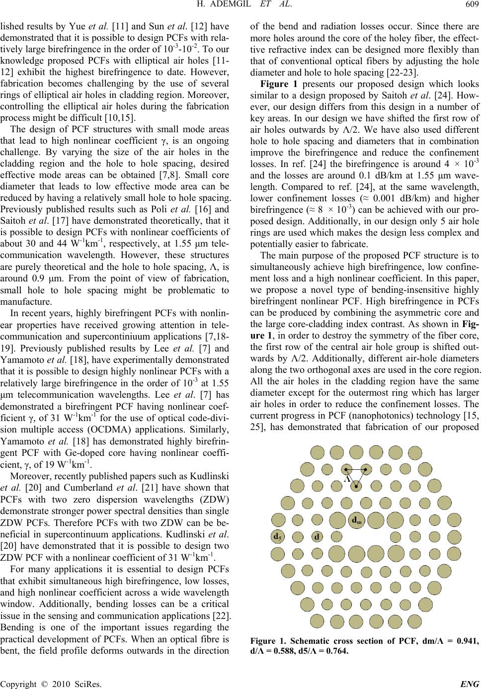 H. ADEMGIL ET AL. Copyright © 2010 SciRes. ENG 609 lished results by Yue et al. [11] and Sun et al. [12] have demonstrated that it is possible to design PCFs with rela- tively large birefringence in the order of 10-3-10-2. To our knowledge proposed PCFs with elliptical air holes [11- 12] exhibit the highest birefringence to date. However, fabrication becomes challenging by the use of several rings of elliptical air holes in cladding region. Moreover, controlling the elliptical air holes during the fabrication process might be difficult [10,15]. The design of PCF structures with small mode areas that lead to high nonlinear coefficient γ, is an ongoing challenge. By varying the size of the air holes in the cladding region and the hole to hole spacing, desired effective mode areas can be obtained [7,8]. Small core diameter that leads to low effective mode area can be reduced by having a relatively small hole to hole spacing. Previously published results such as Poli et al. [16] and Saitoh et al. [17] have demonstrated theoretically, that it is possible to design PCFs with nonlinear coefficients of about 30 and 44 W-1km-1, respectively, at 1.55 μm tele- communication wavelength. However, these structures are purely theoretical and the hole to hole spacing, Λ, is around 0.9 μm. From the point of view of fabrication, small hole to hole spacing might be problematic to manufacture. In recent years, highly birefringent PCFs with nonlin- ear properties have received growing attention in tele- communication and supercontiniuum applications [7,18- 19]. Previously published results by Lee et al. [7] and Yamamoto et al. [18], have experimentally demonstrated that it is possible to design highly nonlinear PCFs with a relatively large birefringence in the order of 10-3 at 1.55 μm telecommunication wavelengths. Lee et al. [7] has demonstrated a birefringent PCF having nonlinear coef- ficient γ, of 31 W-1km-1 for the use of optical code-divi- sion multiple access (OCDMA) applications. Similarly, Yamamoto et al. [18] has demonstrated highly birefrin- gent PCF with Ge-doped core having nonlinear coeffi- cient, γ, of 19 W-1km-1. Moreover, recently published papers such as Kudlinski et al. [20] and Cumberland et al. [21] have shown that PCFs with two zero dispersion wavelengths (ZDW) demonstrate stronger power spectral densities than single ZDW PCFs. Therefore PCFs with two ZDW can be be- neficial in supercontinuum applications. Kudlinski et al. [20] have demonstrated that it is possible to design two ZDW PCF with a nonlinear coefficient of 31 W-1km-1. For many applications it is essential to design PCFs that exhibit simultaneous high birefringence, low losses, and high nonlinear coefficient across a wide wavelength window. Additionally, bending losses can be a critical issue in the sensing and communication applications [22]. Bending is one of the important issues regarding the practical development of PCFs. When an optical fibre is bent, the field profile deforms outwards in the direction of the bend and radiation losses occur. Since there are more holes around the core of the holey fiber, the effect- tive refractive index can be designed more flexibly than that of conventional optical fibers by adjusting the hole diameter and hole to hole spacing [22-23]. Figure 1 presents our proposed design which looks similar to a design proposed by Saitoh et al. [24]. How- ever, our design differs from this design in a number of key areas. In our design we have shifted the first row of air holes outwards by Λ/2. We have also used different hole to hole spacing and diameters that in combination improve the birefringence and reduce the confinement losses. In ref. [24] the birefringence is around 4 × 10⁻³ and the losses are around 0.1 dB/km at 1.55 μm wave- length. Compared to ref. [24], at the same wavelength, lower confinement losses (≈ 0.001 dB/km) and higher birefringence (≈ 8 × 10⁻³) can be achieved with our pro- posed design. Additionally, in our design only 5 air hole rings are used which makes the design less complex and potentially easier to fabricate. The main purpose of the proposed PCF structure is to simultaneously achieve high birefringence, low confine- ment loss and a high nonlinear coefficient. In this paper, we propose a novel type of bending-insensitive highly birefringent nonlinear PCF. High birefringence in PCFs can be produced by combining the asymmetric core and the large core-cladding index contrast. As shown in Fig- ure 1, in order to destroy the symmetry of the fiber core, the first row of the central air hole group is shifted out- wards by Λ/2. Additionally, different air-hole diameters along the two orthogonal axes are used in the core region. All the air holes in the cladding region have the same diameter except for the outermost ring which has larger air holes in order to reduce the confinement losses. The current progress in PCF (nanophotonics) technology [15, 25], has demonstrated that fabrication of our proposed Figure 1. Schematic cross section of PCF, dm/Λ = 0.941, d/Λ = 0.588, d5/Λ = 0.764.  H. ADEMGIL ET AL. Copyright © 2010 SciRes. ENG 610 PCF structure is not an issue. Theoretical and experi- menttal investigations by Suzuki et al. [10] have shown that it is possible to fabricate even complex PCF struc- tures by adapting conventional stack and draw methods. However, stack and draw methods [15] are limited to closely-packed geometries such as triangular or honey- comb lattices and cannot easily generate different geom- etries. Alternatively, drilling methods allow great flexi- bility for both the hole size and spacing, but the struc- tures are generally limited to a small number of holes. Another alternative fabrication method is to use the sol- gel method which allows for independent adjustment of the hole size and spacing. The sol-gel method [15] pro- vides additional design flexibility that will be neces- sary for such PCF structures. Additionally, recently pub- lished results by Vu et al. [22] demonstrated experiment- tally, that the fabrication of bending insensitive PCFs is possible and that these fibers are robust against high amounts of bending. In this work, we have employed full vectorial finite element method (FEM) to investigate key modal proper- ties of the proposed index guided PCF. The modal solu- tion approach based on FEM is more flexible and reliable than other techniques. It can represent any arbitrary cross-section more accurately and has been widely used to find the modal solutions of a wide range of optical waveguides [6,26]. The FEM formulation for modal analysis based on anisotropic perfectly matched layers (PML) is capable of handling as many modes as required and analyse leaky modes. By using PMLs boundary con- dition, propagation characteristics and optical properties of leaky modes in PCFs, it can be precisely evaluated [27]. The modal analysis has been applied on the cross- section in the x-y plane of the PCF as the wave is propa- gating in the z direction. In this study, birefringence, confinement loss, effec- tive mode area, nonlinear coefficient properties of the proposed PCFs are reported thoroughly. Also, significant improvements of propagation characteristics of the PCFs are demonstrated. Following this introduction, a brief theoretical analysis is provided in Section 2. The simula- tion results are reported in Section 3 and, finally, conclu- sions are drawn in the last section. 2. Theory The PCF cross section of Figure 1, with a finite number of air holes is divided into homogeneous subspaces where Maxwell’s equations are solved by accounting for the adjacent subspaces. These subspaces are triangles that allow a good approximation of the circular structures. Using the anisotropic PML [6-26] from the Maxwell equations the following vectorial equation is derived: (E) - 22 0 kn E = 0 (1) where E is the electric field vector, k0 (= 2π/λ) is the wave-number in the vacuum, n is the refractive index of the domain, [s] is the PML matrix, [s]-1 is an inverse ma- trix of [s] and λ is the operating wavelength. 2.1. Confinement and Bending Loss Due to a finite number of layers of air holes, it is inevitable that the optical mode will leak from the core region into the outer air hole region. Considering the fact that the jacket of the PCF is far from cladding and core regions, the light guidance in the core region is exclu- sively due to a finite number of layers of air holes in the silica extending to infinity. The amount of leakage constitutes the confinement loss. The confinement loss is calculated from the imaginary part of the complex effective index, neff using [5,6,26]: 3 40 ..Im 10 ln 10eff ConfLossn [dB/km] (2) where Im is the imaginary part of the neff. The calculations of the bending loss were carried out using the same formulation. We assume a circular bend structure where the PML is used along the radiation di- rection (+x direction) for suppressing spurious reflection. The curved fiber is replaced by a straight fiber with an equivalent refractive index distribution defined by [9,22- 23]. neq = n (x,y)exp x R (3) where n (x,y) is the refractive index profile of the straight fiber and R represents the bend radius. 2.2. Effective Mode Area and Nonlinear Coefficient Another key factor in designing PCFs is the effective mode area. The effective mode area, Aeff is related to the effective area of the core area, which is calculated using [9,26]; 2 2 4 eff Edxdy A Edxdy (4) where E is the amplitude of the transverse electric field propagating inside the fibre. Study of Aeff is thus an important starting point in the understanding of the nonlinear phenomena in PCFs. Due to the high index contrast between silica and air, PCF technology offers the possibility of much tighter mode confinement and thereby a lower effective mode area compared to conventional fibres. An important value for the calculation of the strength of nonlinear effects, is the ratio between the nonlinear refractive-index coefficient, n2 (Kerr constant), and the effective area for a given wavelength of the optical field. The nonlinear coefficient 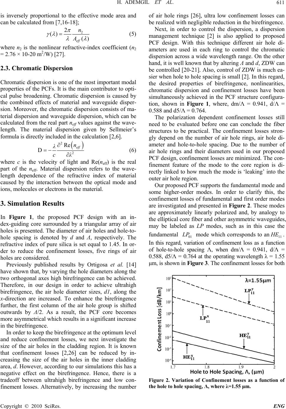 H. ADEMGIL ET AL. Copyright © 2010 SciRes. ENG 611 is inversely proportional to the effective mode area and can be calculated from [7,16-18]; 2 2 () () eff n A (5) where n2 is the nonlinear refractive-index coefficient (n2 = 2.76 × 10⁻²⁰ m2/W) [27]. 2.3. Chromatic Dispersion Chromatic dispersion is one of the most important modal properties of the PCFs. It is the main contributor to opti- cal pulse broadening. Chromatic dispersion is caused by the combined effects of material and waveguide disper- sion. Moreover, the chromatic dispersion consists of ma- terial dispersion and waveguide dispersion, which can be calculated from the real part neff values against the wave- length. The material dispersion given by Sellmeier’s formula is directly included in the calculation [2,6]. 2 2 Re Deff n λ cλ (6) where c is the velocity of light and Re(neff ) is the real part of the neff. Material dispersion refers to the wave- length dependence of the refractive index of material caused by the interaction between the optical mode and ions, molecules or electrons in the material. 3. Simulation Results In Figure 1, the proposed PCF design with an in- dex-guiding core surrounded by a triangular array of air holes is presented. The diameter of air holes and hole-to- hole spacing is denoted by d and Λ, respectively. The refractive index of pure silica is set equal to 1.45. In or- der to reduce the confinement losses, five rings of air holes are considered. Previously published results by Ortigosa et al. [14] have shown that, by varying the hole diameters along the two orthogonal axes high birefringence can be achieved. Therefore, in our design in order to achieve ultrahigh birefringence, the air hole diameter sizes, d1, along the x-direction are increased. To enhance the birefringence further, the first column of the air hole group is shifted outwards by Λ/2. As a result, the PCF core becomes more asymmetrical which results in a significant increase in the birefringence. In order to keep the birefringence at the optimum level and reduce confinement losses, we next investigate the size of the air holes in the cladding region. It is known that confinement losses [2,26] can be reduced by in- creasing the size of the air holes in the inner cladding area, d. However, according to our simulations this has a negative effect on the birefringence. Hence, there is a tradeoff between ultrahigh birefringence and low con- finement losses. Alternatively, by increasing the number of air hole rings [26], ultra low confinement losses can be realized with negligible reduction in the birefringence. Next, in order to control the dispersion, a dispersion management technique [2] is also applied to proposed PCF design. With this technique different air hole di- ameters are used in each ring to control the chromatic dispersion across a wide wavelength range. On the other hand, it is well known that by altering Λ and d, ZDW can be controlled [20-21]. Also, control of ZDW is much ea- sier when hole to hole spacing is small [2]. In this regard, the desired properties of birefringence, nonlinearities, chromatic dispersion and confinement losses have been simultaneously achieved in the PCF structure configura- tion, shown in Figure 1, where, dm/Λ = 0.941, d/Λ = 0.588 and d5/Λ = 0.764. The polarization dependent confinement losses still need to be evaluated before one can conclude the fiber structures to be practical. The confinement losses stron- gly depend on the number of air hole rings, air hole di- ameter and hole-to-hole spacing. Due to the number of air hole rings and their diameters used in our proposed PCF design, confinement losses are minimized. The con- finement feature of the mode to the core region is di- rectly linked to how much the mode is ‘leaking’ into the outer air hole region. Our proposed PCF supports the fundamental mode and some higher-order modes. In order to clarify this, the confinement losses of fundamental and first order modes are investigated and presented in Figure 2. These modes are approximately linearly polarized and, by analogy to the elliptical core fiber and other asymmetric waveguides, may be labeled as LP modes, such as in this case the fundamental 01 LP mode which corresponds to an11 H E. In this regard, variation of confinement loss as a function of hole-to-hole spacing Λ, when dm/Λ = 0.941, d/Λ = 0.588, d5/Λ = 0.764 at the operating wavelength λ = 1.55 μm, is shown in Figure 3. The confinement losses for both Figure 2. Variation of Confinement losses as a function of the hole to hole spacing, Λ, where λ=1.55 μm. 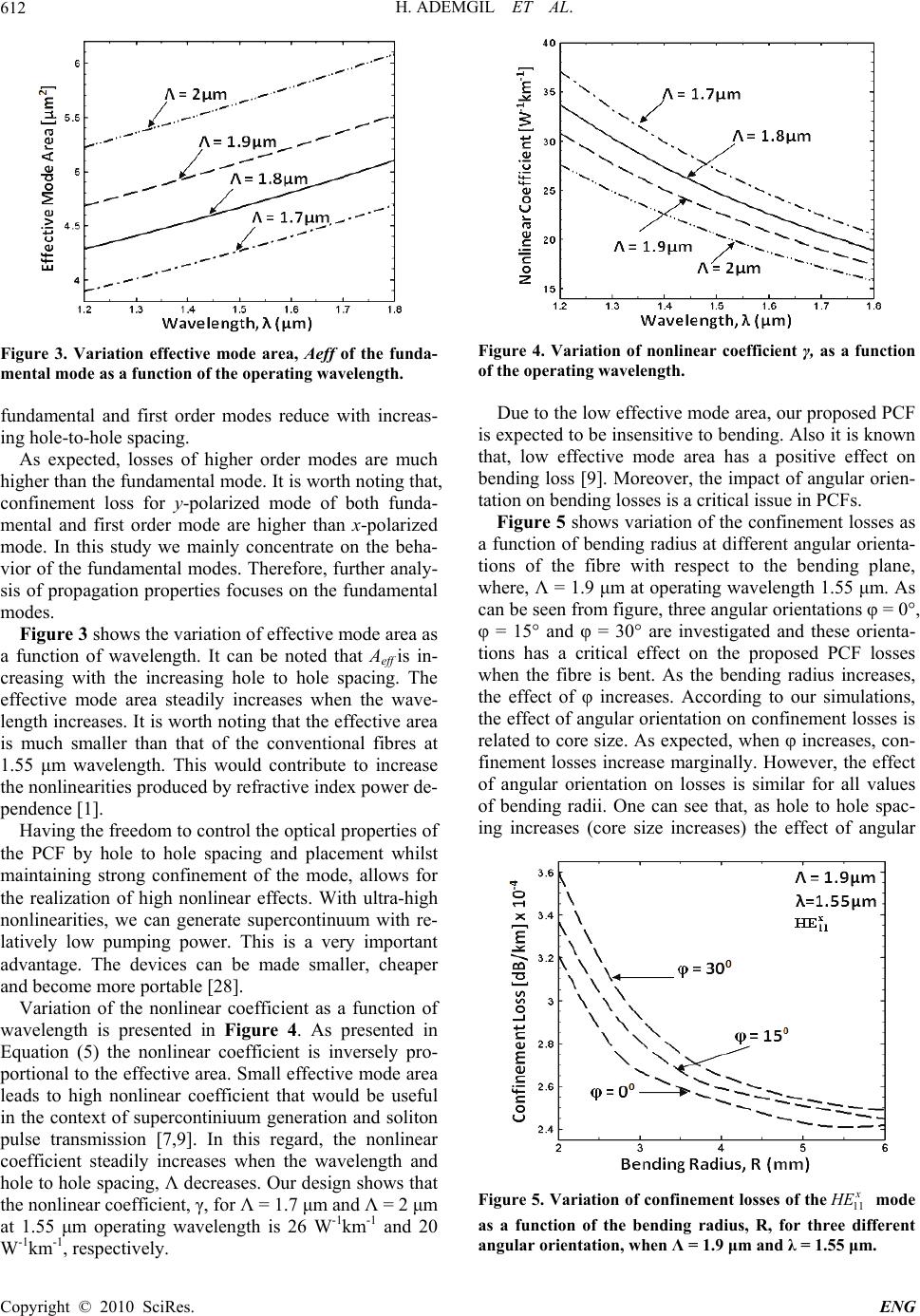 H. ADEMGIL ET AL. Copyright © 2010 SciRes. ENG 612 Figure 3. Variation effective mode area, Aeff of the funda- mental mode as a function of the operating wavelength. fundamental and first order modes reduce with increas- ing hole-to-hole spacing. As expected, losses of higher order modes are much higher than the fundamental mode. It is worth noting that, confinement loss for y-polarized mode of both funda- mental and first order mode are higher than x-polarized mode. In this study we mainly concentrate on the beha- vior of the fundamental modes. Therefore, further analy- sis of propagation properties focuses on the fundamental modes. Figure 3 shows the variation of effective mode area as a function of wavelength. It can be noted that Aeff is in- creasing with the increasing hole to hole spacing. The effective mode area steadily increases when the wave- length increases. It is worth noting that the effective area is much smaller than that of the conventional fibres at 1.55 μm wavelength. This would contribute to increase the nonlinearities produced by refractive index power de- pendence [1]. Having the freedom to control the optical properties of the PCF by hole to hole spacing and placement whilst maintaining strong confinement of the mode, allows for the realization of high nonlinear effects. With ultra-high nonlinearities, we can generate supercontinuum with re- latively low pumping power. This is a very important advantage. The devices can be made smaller, cheaper and become more portable [28]. Variation of the nonlinear coefficient as a function of wavelength is presented in Figure 4. As presented in Equation (5) the nonlinear coefficient is inversely pro- portional to the effective area. Small effective mode area leads to high nonlinear coefficient that would be useful in the context of supercontiniuum generation and soliton pulse transmission [7,9]. In this regard, the nonlinear coefficient steadily increases when the wavelength and hole to hole spacing, Λ decreases. Our design shows that the nonlinear coefficient, γ, for Λ = 1.7 μm and Λ = 2 μm at 1.55 μm operating wavelength is 26 W-1km-1 and 20 W-1km-1, respectively. Figure 4. Variation of nonlinear coefficient γ, as a function of the operating wavelength. Due to the low effective mode area, our proposed PCF is expected to be insensitive to bending. Also it is known that, low effective mode area has a positive effect on bending loss [9]. Moreover, the impact of angular orien- tation on bending losses is a critical issue in PCFs. Figure 5 shows variation of the confinement losses as a function of bending radius at different angular orienta- tions of the fibre with respect to the bending plane, where, Λ = 1.9 μm at operating wavelength 1.55 μm. As can be seen from figure, three angular orientations φ = 0°, φ = 15° and φ = 30° are investigated and these orienta- tions has a critical effect on the proposed PCF losses when the fibre is bent. As the bending radius increases, the effect of φ increases. According to our simulations, the effect of angular orientation on confinement losses is related to core size. As expected, when φ increases, con- finement losses increase marginally. However, the effect of angular orientation on losses is similar for all values of bending radii. One can see that, as hole to hole spac- ing increases (core size increases) the effect of angular Figure 5. Variation of confinement losses of the11 x HE mode as a function of the bending radius, R, for three different angular orientation, when Λ = 1.9 μm and λ = 1.55 μm. 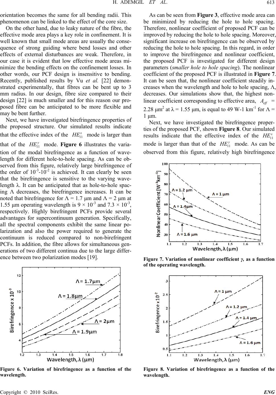 H. ADEMGIL ET AL. Copyright © 2010 SciRes. ENG 613 orientation becomes the same for all bending radii. This phenomenon can be linked to the effect of the core size. On the other hand, due to leaky nature of the fibre, the effective mode area plays a key role in confinement. It is well known that small mode areas are usually the conse- quence of strong guiding where bend losses and other effects of external disturbances are weak. Therefore, in our case it is evident that low effective mode areas mi- nimize the bending effects on the confinement losses. In other words, our PCF design is insensitive to bending. Recently, published results by Vu et al. [22] demon- strated experimentally, that fibres can be bent up to 3 mm radius. In our design, fibre size compared to their design [22] is much smaller and for this reason our pro- posed fibre can be anticipated to be more flexible and may be bent further. Next, we have investigated birefringence properties of the proposed structure. Our simulated results indicate that the effective index of the 11 x H E mode is larger than that of the 11 y H E mode. Figure 6 illustrates the varia- tion of the modal birefringence as a function of wave- length for different hole-to-hole spacing. As can be ob- served from this figure, relatively large birefringence of the order of 10-3-10-2 is achieved. It can clearly be seen that the birefringence is sensitive to the varying wave- length λ. It can be anticipated that as hole-to-hole spac- ing Λ decreases, the birefringence increases. It can be noted that birefringence for Λ = 1.7 μm and Λ = 2 μm at 1.55 μm operating wavelength is 9 × 10⁻³ and 7.3 × 10⁻³, respectively. Highly birefringent PCFs provide several advantages for supercontinuum generation. Specifically, all the spectral components exhibit the same linear po- larization and also the power required to generate the continuum is reduced compared to non-birefringent PCFs. In addition, the fibre allows for simultaneous gen- erations of two different continua due to the large differ- ence between two polarization modes [19]. Figure 6. Variation of birefringence as a function of the wavelength. As can be seen from Figure 3, effective mode area can be minimized by reducing the hole to hole spacing. Therefore, nonlinear coefficient of proposed PCF can be improved by reducing the hole to hole spacing. Moreover, significant increase on birefringence can be observed by reducing the hole to hole spacing. In this regard, in order to improve the birefringence and nonlinear coefficient, the proposed PCF is investigated for different design parameters (smaller hole to hole spacing). The nonlinear coefficient of the proposed PCF is illustrated in Figure 7. It can be seen that, the nonlinear coefficient steadily in- creases when the wavelength and hole to hole spacing, Λ, decreases. Our simulations show that, the highest non- linear coefficient corresponding to effective area, eff A = 2.28 μm2 at λ = 1.55 μm, is equal to 49 W-1 km-1 for Λ = 1 μm. Next, we have investigated the birefringence proper- ties of the proposed PCF, shown Figure 8. Our simulated results indicate that the effective index of the 11 x H E mode is larger than that of the 11 y H E mode. As can be observed from this figure, relatively high birefringence Figure 7. Variation of nonlinear coefficient γ, as a function of the operating wavelength. Figure 8. Variation of birefringence as a function of the wavelength. 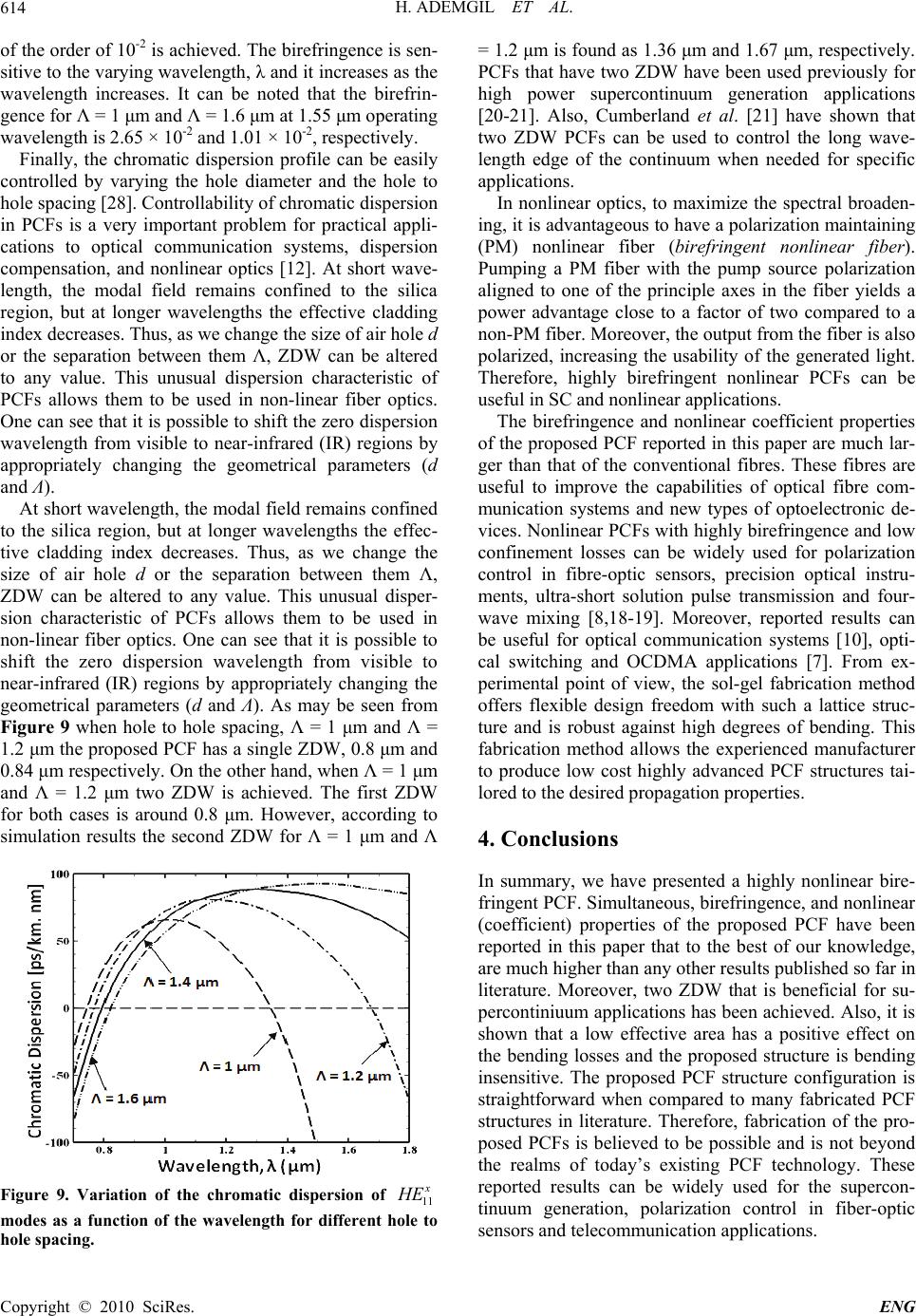 H. ADEMGIL ET AL. Copyright © 2010 SciRes. ENG 614 of the order of 10-2 is achieved. The birefringence is sen- sitive to the varying wavelength, λ and it increases as the wavelength increases. It can be noted that the birefrin- gence for Λ = 1 μm and Λ = 1.6 μm at 1.55 μm operating wavelength is 2.65 × 10⁻² and 1.01 × 10⁻², respectively. Finally, the chromatic dispersion profile can be easily controlled by varying the hole diameter and the hole to hole spacing [28]. Controllability of chromatic dispersion in PCFs is a very important problem for practical appli- cations to optical communication systems, dispersion compensation, and nonlinear optics [12]. At short wave- length, the modal field remains confined to the silica region, but at longer wavelengths the effective cladding index decreases. Thus, as we change the size of air hole d or the separation between them Λ, ZDW can be altered to any value. This unusual dispersion characteristic of PCFs allows them to be used in non-linear fiber optics. One can see that it is possible to shift the zero dispersion wavelength from visible to near-infrared (IR) regions by appropriately changing the geometrical parameters (d and Λ). At short wavelength, the modal field remains confined to the silica region, but at longer wavelengths the effec- tive cladding index decreases. Thus, as we change the size of air hole d or the separation between them Λ, ZDW can be altered to any value. This unusual disper- sion characteristic of PCFs allows them to be used in non-linear fiber optics. One can see that it is possible to shift the zero dispersion wavelength from visible to near-infrared (IR) regions by appropriately changing the geometrical parameters (d and Λ). As may be seen from Figure 9 when hole to hole spacing, Λ = 1 μm and Λ = 1.2 μm the proposed PCF has a single ZDW, 0.8 μm and 0.84 μm respectively. On the other hand, when Λ = 1 μm and Λ = 1.2 μm two ZDW is achieved. The first ZDW for both cases is around 0.8 μm. However, according to simulation results the second ZDW for Λ = 1 μm and Λ Figure 9. Variation of the chromatic dispersion of 11 x H E modes as a function of the wavelength for different hole to hole spacing. = 1.2 μm is found as 1.36 μm and 1.67 μm, respectively. PCFs that have two ZDW have been used previously for high power supercontinuum generation applications [20-21]. Also, Cumberland et al. [21] have shown that two ZDW PCFs can be used to control the long wave- length edge of the continuum when needed for specific applications. In nonlinear optics, to maximize the spectral broaden- ing, it is advantageous to have a polarization maintaining (PM) nonlinear fiber (birefringent nonlinear fiber). Pumping a PM fiber with the pump source polarization aligned to one of the principle axes in the fiber yields a power advantage close to a factor of two compared to a non-PM fiber. Moreover, the output from the fiber is also polarized, increasing the usability of the generated light. Therefore, highly birefringent nonlinear PCFs can be useful in SC and nonlinear applications. The birefringence and nonlinear coefficient properties of the proposed PCF reported in this paper are much lar- ger than that of the conventional fibres. These fibres are useful to improve the capabilities of optical fibre com- munication systems and new types of optoelectronic de- vices. Nonlinear PCFs with highly birefringence and low confinement losses can be widely used for polarization control in fibre-optic sensors, precision optical instru- ments, ultra-short solution pulse transmission and four- wave mixing [8,18-19]. Moreover, reported results can be useful for optical communication systems [10], opti- cal switching and OCDMA applications [7]. From ex- perimental point of view, the sol-gel fabrication method offers flexible design freedom with such a lattice struc- ture and is robust against high degrees of bending. This fabrication method allows the experienced manufacturer to produce low cost highly advanced PCF structures tai- lored to the desired propagation properties. 4. Conclusions In summary, we have presented a highly nonlinear bire- fringent PCF. Simultaneous, birefringence, and nonlinear (coefficient) properties of the proposed PCF have been reported in this paper that to the best of our knowledge, are much higher than any other results published so far in literature. Moreover, two ZDW that is beneficial for su- percontiniuum applications has been achieved. Also, it is shown that a low effective area has a positive effect on the bending losses and the proposed structure is bending insensitive. The proposed PCF structure configuration is straightforward when compared to many fabricated PCF structures in literature. Therefore, fabrication of the pro- posed PCFs is believed to be possible and is not beyond the realms of today’s existing PCF technology. These reported results can be widely used for the supercon- tinuum generation, polarization control in fiber-optic sensors and telecommunication applications. 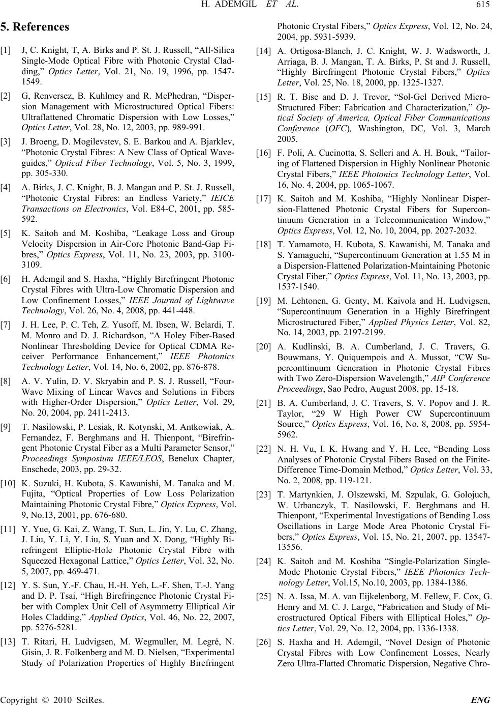 H. ADEMGIL ET AL. Copyright © 2010 SciRes. ENG 615 5. References [1] J, C. Knight, T, A. Birks and P. St. J. Russell, “All-Silica Single-Mode Optical Fibre with Photonic Crystal Clad- ding,” Optics Letter, Vol. 21, No. 19, 1996, pp. 1547- 1549. [2] G, Renversez, B. Kuhlmey and R. McPhedran, “Disper- sion Management with Microstructured Optical Fibers: Ultraflattened Chromatic Dispersion with Low Losses,” Optics Letter, Vol. 28, No. 12, 2003, pp. 989-991. [3] J. Broeng, D. Mogilevstev, S. E. Barkou and A. Bjarklev, “Photonic Crystal Fibres: A New Class of Optical Wave- guides,” Optical Fiber Technology, Vol. 5, No. 3, 1999, pp. 305-330. [4] A. Birks, J. C. Knight, B. J. Mangan and P. St. J. Russell, “Photonic Crystal Fibres: an Endless Variety,” IEICE Transactions on Electronics, Vol. E84-C, 2001, pp. 585- 592. [5] K. Saitoh and M. Koshiba, “Leakage Loss and Group Velocity Dispersion in Air-Core Photonic Band-Gap Fi- bres,” Optics Express, Vol. 11, No. 23, 2003, pp. 3100- 3109. [6] H. Ademgil and S. Haxha, “Highly Birefringent Photonic Crystal Fibres with Ultra-Low Chromatic Dispersion and Low Confinement Losses,” IEEE Journal of Lightwave Technology, Vol. 26, No. 4, 2008, pp. 441-448. [7] J. H. Lee, P. C. Teh, Z. Yusoff, M. Ibsen, W. Belardi, T. M. Monro and D. J. Richardson, “A Holey Fiber-Based Nonlinear Thresholding Device for Optical CDMA Re- ceiver Performance Enhancement,” IEEE Photonics Technology Letter, Vol. 14, No. 6, 2002, pp. 876-878. [8] A. V. Yulin, D. V. Skryabin and P. S. J. Russell, “Four- Wave Mixing of Linear Waves and Solutions in Fibers with Higher-Order Dispersion,” Optics Letter, Vol. 29, No. 20, 2004, pp. 2411-2413. [9] T. Nasilowski, P. Lesiak, R. Kotynski, M. Antkowiak, A. Fernandez, F. Berghmans and H. Thienpont, “Birefrin- gent Photonic Crystal Fiber as a Multi Parameter Sensor,” Proceedings Symposium IEEE/LEOS, Benelux Chapter, Enschede, 2003, pp. 29-32. [10] K. Suzuki, H. Kubota, S. Kawanishi, M. Tanaka and M. Fujita, “Optical Properties of Low Loss Polarization Maintaining Photonic Crystal Fibre,” Optics Express, Vol. 9, No.13, 2001, pp. 676-680. [11] Y. Yue, G. Kai, Z. Wang, T. Sun, L. Jin, Y. Lu, C. Zhang, J. Liu, Y. Li, Y. Liu, S. Yuan and X. Dong, “Highly Bi- refringent Elliptic-Hole Photonic Crystal Fibre with Squeezed Hexagonal Lattice,” Optics Letter, Vol. 32, No. 5, 2007, pp. 469-471. [12] Y. S. Sun, Y.-F. Chau, H.-H. Yeh, L.-F. Shen, T.-J. Yang and D. P. Tsai, “High Birefringence Photonic Crystal Fi- ber with Complex Unit Cell of Asymmetry Elliptical Air Holes Cladding,” Applied Optics, Vol. 46, No. 22, 2007, pp. 5276-5281. [13] T. Ritari, H. Ludvigsen, M. Wegmuller, M. Legré, N. Gisin, J. R. Folkenberg and M. D. Nielsen, “Experimental Study of Polarization Properties of Highly Birefringent Photonic Crystal Fibers,” Optics Express, Vol. 12, No. 24, 2004, pp. 5931-5939. [14] A. Ortigosa-Blanch, J. C. Knight, W. J. Wadsworth, J. Arriaga, B. J. Mangan, T. A. Birks, P. St and J. Russell, “Highly Birefringent Photonic Crystal Fibers,” Optics Letter, Vol. 25, No. 18, 2000, pp. 1325-1327. [15] R. T. Bise and D. J. Trevor, “Sol-Gel Derived Micro- Structured Fiber: Fabrication and Characterization,” Op- tical Society of America, Optical Fiber Communications Conference (OFC), Washington, DC, Vol. 3, March 2005. [16] F. Poli, A. Cucinotta, S. Selleri and A. H. Bouk, “Tailor- ing of Flattened Dispersion in Highly Nonlinear Photonic Crystal Fibers,” IEEE Photonics Technology Letter, Vol. 16, No. 4, 2004, pp. 1065-1067. [17] K. Saitoh and M. Koshiba, “Highly Nonlinear Disper- sion-Flattened Photonic Crystal Fibers for Supercon- tinuum Generation in a Telecommunication Window,” Optics Express, Vol. 12, No. 10, 2004, pp. 2027-2032. [18] T. Yamamoto, H. Kubota, S. Kawanishi, M. Tanaka and S. Yamaguchi, “Supercontinuum Generation at 1.55 M in a Dispersion-Flattened Polarization-Maintaining Photonic Crystal Fiber,” Optics Express, Vol. 11, No. 13, 2003, pp. 1537-1540. [19] M. Lehtonen, G. Genty, M. Kaivola and H. Ludvigsen, “Supercontinuum Generation in a Highly Birefringent Microstructured Fiber,” Applied Physics Letter, Vol. 82, No. 14, 2003, pp. 2197-2199. [20] A. Kudlinski, B. A. Cumberland, J. C. Travers, G. Bouwmans, Y. Quiquempois and A. Mussot, “CW Su- perconttinuum Generation in Photonic Crystal Fibres with Two Zero-Dispersion Wavelength,” AIP Conference Proceedings, Sao Pedro, August 2008, pp. 15-18. [21] B. A. Cumberland, J. C. Travers, S. V. Popov and J. R. Taylor, “29 W High Power CW Supercontinuum Source,” Optics Express, Vol. 16, No. 8, 2008, pp. 5954- 5962. [22] N. H. Vu, I. K. Hwang and Y. H. Lee, “Bending Loss Analyses of Photonic Crystal Fibers Based on the Finite- Difference Time-Domain Method,” Optics Letter, Vol. 33, No. 2, 2008, pp. 119-121. [23] T. Martynkien, J. Olszewski, M. Szpulak, G. Golojuch, W. Urbanczyk, T. Nasilowski, F. Berghmans and H. Thienpont, “Experimental Investigations of Bending Loss Oscillations in Large Mode Area Photonic Crystal Fi- bers,” Optics Express, Vol. 15, No. 21, 2007, pp. 13547- 13556. [24] K. Saitoh and M. Koshiba “Single-Polarization Single- Mode Photonic Crystal Fibers,” IEEE Photonics Tech- nology Letter, Vol.15, No.10, 2003, pp. 1384-1386. [25] N. A. Issa, M. A. van Eijkelenborg, M. Fellew, F. Cox, G. Henry and M. C. J. Large, “Fabrication and Study of Mi- crostructured Optical Fibers with Elliptical Holes,” Op- tics Letter, Vol. 29, No. 12, 2004, pp. 1336-1338. [26] S. Haxha and H. Ademgil, “Novel Design of Photonic Crystal Fibres with Low Confinement Losses, Nearly Zero Ultra-Flatted Chromatic Dispersion, Negative Chro-  H. ADEMGIL ET AL. Copyright © 2010 SciRes. ENG 616 matic Dispersion and Improved Effective Mode Area,” Journal of Optics Communications, Vol. 281, No. 2, 2008, pp. 278-286. [27] T. Kato, Y. Suetsugu and M. Nishimura “Estimation of Nonlinear Refractive Index in Various Silica-Based Gla- sses for Optical Fibers,” Optics Letter, Vol. 20, No. 22, 1995, pp. 2279-2281. [28] P.-A. Champert, V. Couderc, P. Leproux, S. Février, V. Tombelaine, L. Labonté, P. Roy, C. Froehly and P. Nérin, “White-Light Supercontinuum Generation in Normally Dispersive Optical Fiber Using Original Multi-Wave- length Pumping System,” Optics Express, Vol. 12, No. 19, 2004, pp. 4366-4371. |

