Paper Menu >>
Journal Menu >>
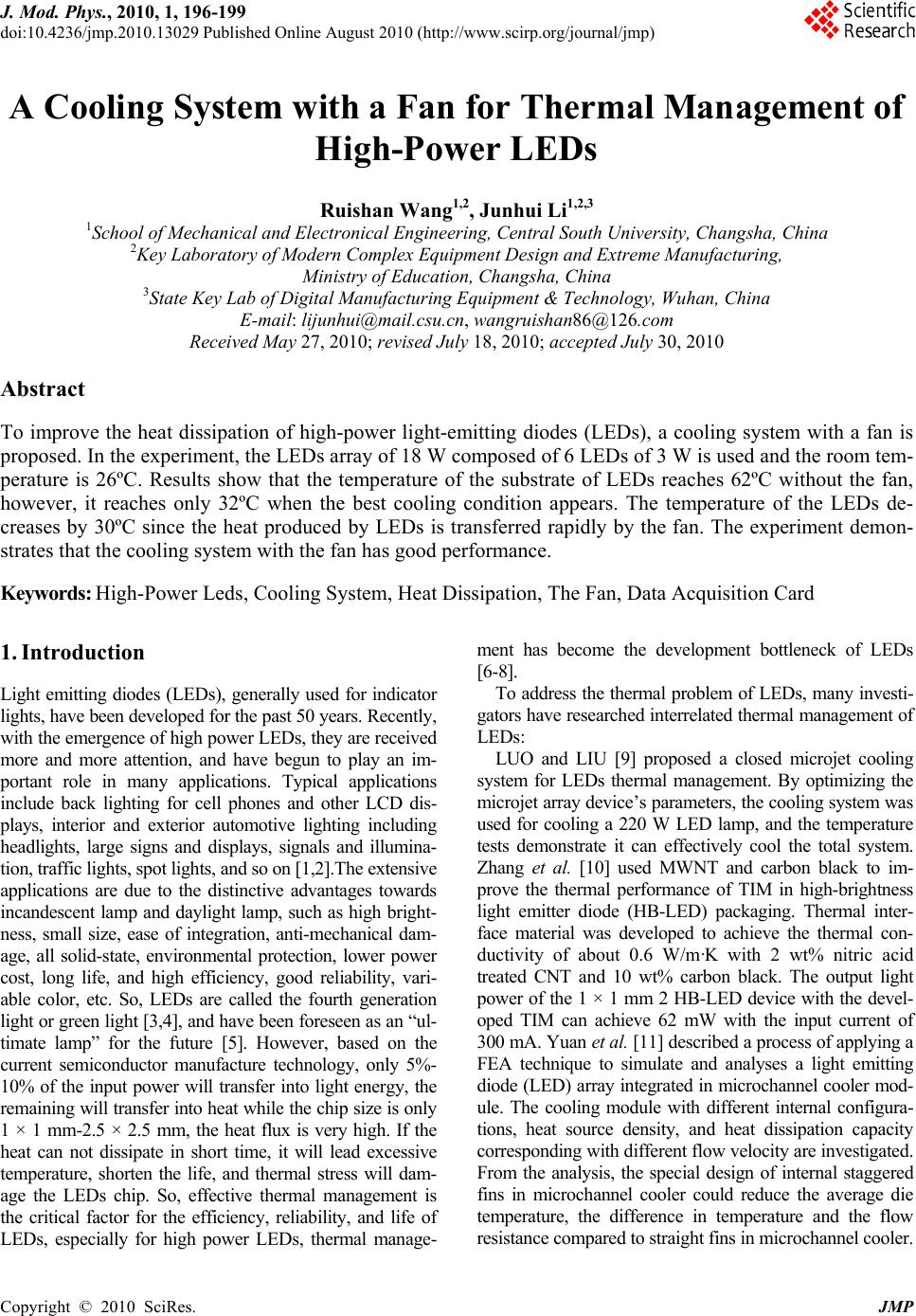 J. Mod. Phys., 2010, 1, 196-199 doi:10.4236/jmp.2010.13029 Published Online August 2010 (http://www.scirp.org/journal/jmp) Copyright © 2010 SciRes. JMP A Cooling System with a Fan for Thermal Management of High-Power LEDs Ruishan Wang1,2, Junhui Li1,2,3 1School of Mechanical and Electronical Engineering, Central South University, Changsha, China 2Key Laboratory of Modern Complex Equipme nt Desi g n an d Extr eme Manufacturing, Ministry of Education, Changsha, China 3State Key Lab of Digital Manufacturing Equipment & Technology, Wuhan, China E-mail: lijunhui@mail.csu.cn, wangruishan86@126.com Received May 27, 2010; revised July 18, 2010; accepted July 30, 2010 Abstract To improve the heat dissipation of high-power light-emitting diodes (LEDs), a cooling system with a fan is proposed. In the experiment, the LEDs array of 18 W composed of 6 LEDs of 3 W is used and the room tem- perature is 26ºC. Results show that the temperature of the substrate of LEDs reaches 62ºC without the fan, however, it reaches only 32ºC when the best cooling condition appears. The temperature of the LEDs de- creases by 30ºC since the heat produced by LEDs is transferred rapidly by the fan. The experiment demon- strates that the cooling system with the fan has good performance. Keywords: High-Power Leds, Cooling System, Heat Dissipation, The Fan, Data Acquisition Card 1. Introduction Light emitting diodes (LEDs), generally used for indicator lights, have been developed for the past 50 years. Recently, with the emerg ence of high po wer LEDs, they are receiv ed more and more attention, and have begun to play an im- portant role in many applications. Typical applications include back lighting for cell phones and other LCD dis- plays, interior and exterior automotive lighting including headlights, large signs and displays, signals and illumina- tion, traffic lights, spot lights, and so on [1,2].The extensive applications are due to the distinctive advantages towards incandescent lamp and daylight lamp, such as high bright- ness, small size, ease of integration, anti-mechanical dam- age, all solid-state, environmental protection, lower power cost, long life, and high efficiency, good reliability, vari- able color, etc. So, LEDs are called the fourth generation light or green light [3,4], and have been foreseen as an “ul- timate lamp” for the future [5]. However, based on the current semiconductor manufacture technology, only 5%- 10% of the input power will transfer into light energy, the remainin g will transf er into he at while the ch ip size i s only 1 × 1 mm-2.5 × 2.5 mm, the heat flux is very high. If the heat can not dissipate in short time, it will lead excessive temperature, shorten the life, and thermal stress will dam- age the LEDs chip. So, effective thermal management is the critical factor for the efficiency, reliability, and life of LEDs, especially for high power LEDs, thermal manage- ment has become the development bottleneck of LEDs [6-8]. To address the thermal problem of LEDs, many investi- gators have researched in terrelated ther mal management of LEDs: LUO and LIU [9] proposed a closed microjet cooling system for LEDs thermal management. By optimizing the microjet array device’s parameters, the cooling system was used for cooling a 220 W LED lamp, and the temperature tests demonstrate it can effectively cool the total system. Zhang et al. [10] used MWNT and carbon black to im- prove the thermal performance of TIM in high-brightness light emitter diode (HB-LED) packaging. Thermal inter- face material was developed to achieve the thermal con- ductivity of about 0.6 W/m·K with 2 wt% nitric acid treated CNT and 10 wt% carbon black. The output light power of the 1 × 1 mm 2 HB-LED device with the devel- oped TIM can achieve 62 mW with the input current of 300 mA. Yuan et al. [11] described a process of applying a FEA technique to simulate and analyses a light emitting diode (LED) array integrated in microchannel cooler mod- ule. The cooling module with different internal configura- tions, heat source density, and heat dissipation capacity corresponding with different flow velocity are investigated. From the analysis, the special design of internal staggered fins in microchannel cooler could reduce the average die temperature, the difference in temperature and the flow resistance compared to straight fins in microchannel cooler. 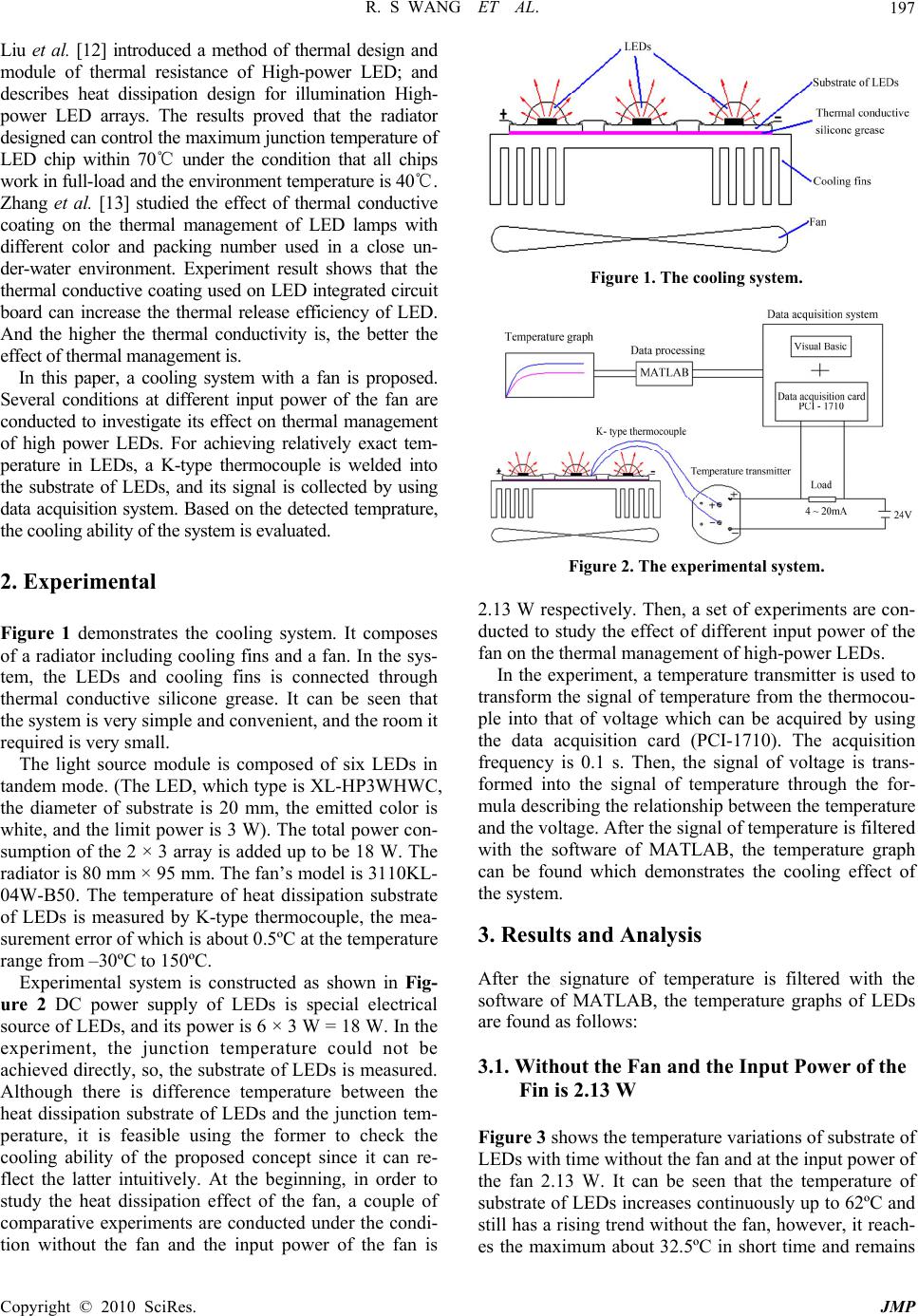 R. S WANG ET AL. Copyright © 2010 SciRes. JMP 197 Liu et al. [12] introduced a method of thermal design and module of thermal resistance of High-power LED; and describes heat dissipation design for illumination High- power LED arrays. The results proved that the radiator designed can control the maximum junction temperature of LED chip within 70 under the condition that all chips ℃ work in full- lo a d an d the envir onment temp er ature is 40. ℃ Zhang et al. [13] studied the effect of thermal conductive coating on the thermal management of LED lamps with different color and packing number used in a close un- der-water environment. Experiment result shows that the thermal conductive coating used on LED integrated circuit board can increase the thermal release efficiency of LED. And the higher the thermal conductivity is, the better the effect of thermal management is. In this paper, a cooling system with a fan is proposed. Several conditions at different input power of the fan are conducted to investigate its effect on thermal management of high power LEDs. For achieving relatively exact tem- perature in LEDs, a K-type thermocouple is welded into the substrate of LEDs, and its signal is collected by using data acquisition system. Based on the detected temprature, the cooling ability of the system is evaluated. 2. Experimental Figure 1 demonstrates the cooling system. It composes of a radiator including cooling fins and a fan. In the sys- tem, the LEDs and cooling fins is connected through thermal conductive silicone grease. It can be seen that the system is very simple and convenient, and the room it required is very small. The light source module is composed of six LEDs in tandem mode. (The LED, which type is XL-HP3WHWC, the diameter of substrate is 20 mm, the emitted color is white, and the limit power is 3 W). The total power con- sumption of the 2 × 3 array is added up to be 18 W. The radiator is 80 mm × 95 mm. The fan’s model is 3110KL- 04W-B50. The temperature of heat dissipation substrate of LEDs is measured by K-type thermocouple, the mea- surement error of which is about 0.5ºC at the temperature range from –30ºC to 150ºC. Experimental system is constructed as shown in Fig- ure 2 DC power supply of LEDs is special electrical source of LEDs, and its power is 6 × 3 W = 18 W. In the experiment, the junction temperature could not be achieved directly, so, the substrate of LEDs is measured. Although there is difference temperature between the heat dissipation substrate of LEDs and the junction tem- perature, it is feasible using the former to check the cooling ability of the proposed concept since it can re- flect the latter intuitively. At the beginning, in order to study the heat dissipation effect of the fan, a couple of comparative experiments are conducted under the condi- tion without the fan and the input power of the fan is Figure 1. The cooling system. Figure 2. The experimental system. 2.13 W respectively. Then, a set of experiments are con- ducted to study the effect of different inpu t power of the fan on the thermal management of high-power LEDs. In the experiment, a temperature transmitter is u sed to transform the signal of temperature from the thermocou- ple into that of voltage which can be acquired by using the data acquisition card (PCI-1710). The acquisition frequency is 0.1 s. Then, the signal of voltage is trans- formed into the signal of temperature through the for- mula describing the relationship between the temperature and the voltage. After the signal o f temperature is filtered with the software of MATLAB, the temperature graph can be found which demonstrates the cooling effect of the system. 3. Results and Analysis After the signature of temperature is filtered with the software of MATLAB, the temperature graphs of LEDs are found as follows: 3.1. Without the Fan and the Input Power of the Fin is 2.13 W Figure 3 shows the temperature variations of substrate of LEDs with time without the fan and at the input power of the fan 2.13 W. It can be seen that the temperature of substrate of LEDs increases continuously up to 62ºC and still has a rising trend without the fan, however, it reach- es the maximum about 32.5ºC in short time and remains  R. S WANG ET AL. Copyright © 2010 SciRes. JMP 198 Figure 3. The temperature variations of substrate of LEDs with time without the fan and at the input power of the fan 2.13 W. steady by using the fan. The above result is easy to un- derstand that the heat generated by LEDs conducts to the cooling fins, if the heat of cooling fins does not released into the environment in time, the temperature of LEDs will increases continually. In the designed system, the main approach of heat exchange between the system and environment is natural convection though cooling fins when the fan is not used. However, when the fan works, it is forced convection, and the effect of heat exchange will be effectively improved. This indicated that the fan has a good performance on the thermal management of high-power LEDs. 3.2. The Different Input Power of the Fan Figure 4 shows the temperature variations of substrate of LEDs with time at different input power of the fan. It can be seen that the temperature of substrate of LEDs will reach a steady value within 5 mins when the fan is used, and the steady temperatures are different with the differ- ent input power of th e fan. The ma ximum a nd mini mum Figure 4. The temperature variations of substrate of LEDs with time at different input power of the fan. temperature is 35.6ºC and 32ºC when the input power is 0.23 W and 3.22 W respectively. The higher the input power is, the lower the steady temperature is. As the en- largement of input power, forced convection enhanced, fluid can quickly remove LED heat, leading to the lower temperature of the substrate of LEDs, while the running cost is correspondingly increased. In the practical appli- cations based on the above experiment, a choice should be made to achieve a balance between the cooling effect and the power consumption of the system. Figure 4 shows that 0.83 W and 1.2 2 W of the system is appropr i- ated. 4. Conclusions A cooling system with a fan is presented to improve the heat dissipation of high-power LEDs. Several conditions at different input power of the fan are conducted. The experimental result demonstrates that the cooling system with the fan has a good performance on the thermal management of high-power LEDs. The minimum tem- perature is only 32ºC when the fan is applied and the environment temperature is 26ºC, while it reaches 62ºC without the fan. With the increasing of the input power, however, the cooling performance improves slightly, so, in practical applications, appropriate input power should be selected to achieve a good balance between the cool- ing effect and the power consumption of the system. 5. Acknowledgements This work was supported by National Natural Science Foundation of China (No. 50975292, 50705098), the China High Technology R & D Program 973 (No. 2009 CB724203), Hunan Natural Science Foundation of China (No. 07JJ3091), State Ke y Lab of Digital Manufacturing Equipment and Technology of China (No. 2007001), National S & T Major Project of China (No. 2009ZX020 38), and Program for New Century Excellent Talents in University (No. NCET-08-0575). 6. References [1] W. H. Chi, T. L. Chou, C. N. Han and K. N. Chiang, “Analysis of Thermal Performance of High Power Light Emitting Diodes Package,” International Conference on Electronics Packaging Technology, Nanjing, 2008, pp. 533-538. [2] X. Luo, W. Xiong and S. Liu, “A Simplified Thermal Resistance Network Model for High Power LED Street Lamp,” International Conference on Electronic Packag- ing Technology & High Density Packaging, Shanghai, 2008, pp. 1-7. [3] B. Li, “Lumen Efficiency of 1 W-Level High Power White LED,” Semiconductor Optoelectronics, Vol. 26, No. 4, 2005, pp. 314-316.  R. S WANG ET AL. Copyright © 2010 SciRes. JMP 199 [4] X. He, B. Cheng, L. Yin and J. Zhang, “Testing System for Thermal Resistance of High-Power LED,” Electronic Measuremient Technology, Vol. 31, No. 9, 2008, pp. 17- 20. [5] N. Holonyak, “Is the Light Emitting Diode (LED) an Ultimate Lamp?” American Journal of Physics, Vol. 68, No. 9, 2000, pp. 864-868. [6] W. Dai, J. Wang and Y. Li, “Transient Thermal Analysis of High-power LED Package,” Semiconductor Optoelec- tronics, Vol. 29, No. 3, 2008, pp. 324-328. [7] B. Yu and Y. Wang, “Junction Temperature and Thermal Resistance Restrict the De veloping of High-power LED,” Chinese Journal of Luminescence, Vol. 26, No. 6, 2005, pp. 761-766. [8] N. Narendran and Y. Gu, “Life of LED-Based White Light Source,” IEEE/OSA Journal of Display Technology, Vol. 1, No. 1, 2005, pp. 167-171. [9] X. Luo and S. Liu, “A Microjet Array Cooling System for Thermal Management of High-Brightness LEDs,” IEEE Transactions on Advanced Packaging, Vol. 30, No. 3, 2007, pp. 475-484. [10] K. Zhang, G. Xiao, C. Wong, H. Gu and B. Xu, “Study on Thermal Interface Material with Carbon Nanotubes and Carbon Black in High-Brightness LED Packaging with Flip-Chip Technology,” 55th Electronic Compo- nents and Technology Conference, Lake Buena Vista, 2005, pp. 60-65. [11] L. Yuan, S. Liu, M. Chen and X. Luo, “Thermal Analysis of High Power LED Array Packaging with Microchannel Cooler,” 7th International Conference on Electronic Packaging Technology (ICEPT '06), Shanghai, 2006, pp. 1-5. [12] Y. Liu, G. Fu, C. Gao, X. Li and S. Wang, “Thermal Analysis of Illumination High-Power LED,” Chinese Journal of Electron Devices, Vol. 31, No. 6, 2008, pp. 1716-1719. [13] S. Zhang, L. Fang, G. Fu, X. Tan, J. Dong, Y. Chen and L. Gao, “Effect of Thermal Conductive Coating on Ther- molysis Property of LED,” Semiconductor Optoelectron- ics, Vol. 28, No. 6, 2007, pp. 793-796. |