Paper Menu >>
Journal Menu >>
 Int. J. Communications, Network and System Sciences, 2012, 5, 815-824 http://dx.doi.org/10.4236/ijcns.2012.512086 Published Online December 2012 (http://www.SciRP.org/journal/ijcns) Modeling Components and Services of LTE Mobile Communications System Ishtiaq Ahmed Choudhry1, Nazir Ahmad Zafar2 1Department of Communication and Networking, King Faisal University, Al-Ahsa, KSA 2Department of Computer Science, King Faisal University, Al-Ahsa, KSA Email: ichoudhry@kfu.edu.sa, nazafar@kfu.edu.sa Received October 8, 2012; revised November 10, 2012; accepted November 18, 2012 ABSTRACT The latest wireless broadband network standard is LTE (Long Term Evolution) which is developed by 3GPP (3rd Gen- eration Partnership Project). It will enable mobile devices such as smart phones, tablets and laptops to access Internet at a very high speed along with lots of multimedia services. There are many issues that are yet to be solved due to dynamic complex nature of wireless systems, multimedia software applications and software requirements. Poor service quality, service disconnections due to mobility, seamless handover, handover interruption time and downward compatibility to other Radio Access Networks (RAN) are some of the key issues for the current LTE systems that are addressed very recently in the scientific literature. Formal method is one of the promising software engineering techniques that assure quality and perfection in software system models. Formal methods use mathematical language to explicitly specify sys- tem specifications and requirements that serve as initial grounds for further development and implementation. It effi- ciently handles all component connections and resource management parameters using discrete structures. Z Schema language is used to model static aspects of LTE communications system. All the schemas are being verified using Z/Eves toolset. The aim is to provide sound mathematical foundation for system validation and verification that eventu- ally results in a more reliable, scalable and complete software system. Keywords: LTE Communications System; Formal Methods; Emerging Software; Mathematical Language; Z Notation 1. Introduction Long Term Evolution (LTE), a wireless broadband tech- nology, is designed to support roaming Internet use and access via mobiles phones and other such handset de- vices. LTE is also referred as fourth generation (4G) technology and provides significant improvements over previous cellular communication networks. LTE is the latest wireless standard for International Mobile Tele- communication (IMT) system which has been deployed in many countries and few others are in pipeline for its deployment. LTE can operate in different bandwidths ranging from 1.4 MHz to 20 MHz and will provide a data rate of 100 Mbps to 1 Gbps depending upon the mobility of the user equipment. LTE—Advanced Release 10 is set to provide higher bit rate (DL 3Gbps, UL 1.5 Gbps). The IMT system is a complex one due to its different Radio Access Networks (RAN) and protocols. International Mobile Telecommunication systems allow users to ac- cess services and information at any time and at any place. However, these telecommunication systems pro- vide mobility services with different requirements, re- sources and constraints. For example, poor quality of service, service interruptions due to mobility, seamless handover, interruption time at handovers and downward compatibility to other Radio Access Networks are some of the common key issues that are addressed in the scien- tific literature [1-7]. There are many other issues which need to be addressed due to complexity and dynamic nature of wireless systems, new information technology infrastructure, multimedia applications and software re- quirements. LTE offers many real time multimedia applications by integrating with the existing technologies. Although there exists a lot of research in this area but still there is an uncertainty and sufficient improvement are required in it due to complexity and flexibility of the system. The telecom industry is still discovering the system, network approaches and optimization techniques with the support and cooperation of academics and researches around the globe. Because LTE will integrate many heterogeneous networks and services, the seamless implementation for a complete development of LTE communications system is an open research problem. Formal methods are mathematical techniques used to model software systems. It enables us to write system specification in such a way that it helps us understanding C opyright © 2012 SciRes. IJCNS  I. A. CHOUDHRY, N. A. ZAFAR 816 states of the system and its properties in a rigorous way. Formal methods are effective abstraction technique for managing complexity of large scale, dynamic and dis- tributed systems. By use of formal methods, systems requirements, specification and limitations are addressed at early stages of systems and software development. In this way, a thorough development processes leads to a complete, consistent and robust model. The most impor- tant benefit of using formal methods is that we can move gradually from informal requirements to a detailed model maintaining the system properties and constraints. In the existing work [8], Milner extended the system from Calculus of Communication System to pie-calculus developing a dynamic communication model which can be used to describe the mobility issues. In this work, mo- bility is assumed as movement of links between the con- nected components. Acharya et al., [9] have used formal techniques to overcome the consistency issue at various phases of development process in wireless mobile com- munication networks. Formal models are applied in [10], [11] using Z and object Z, however, few discrepancies are identified and the systems are not addressed com- pletely. Duke et al., [12] have presented several case studies to illustrate application of formal methods. One of his study regarding mobile phone system which keeps track of several states of mobiles with limited number of operations, is an interesting example. The same case study is extended by Battaz in [13] to address the mobil- ity issues explicitly using Z specification language. To further extend the same system, Battaz has described handover procedure among two objects in more details. The requirements capturing and analysis of LTE system is presented in [14]. In our paper, LTE is developed by the 3G Partnership Group (3GPP) [15] and its specifica- tions is laid out mainly focusing on model abstraction. In this paper, formal specification of static structures of the LTE system is presented using Z notation. First of all, fundamental definitions used in the model are pre- sented. Then formal specification of few important ser- vices, phone book, messages and call record is described. In the next, formal description of user equipment is given based on the above definitions. Further, formal descrip- tion of core components, namely, evolved Node B, Home Subscriber Server, Serving Gateway and Mobility Man- agement Entity is described. Finally, LTE system is pre- sented after composition of the above structures. The relationships among the components are defined for well- definedness. An integration of the components is de- scribed in terms of properties. The description of the formal specification is provided by Z notation. The speci- fication of the system is analyzed using Z/Eves toolset. Rest of the paper is organized as: In Section 2, basic model of the LTE communications system is introduced. Formal model using Z notation is provided in Section 3. Model analysis is presented in Section 4. Finally, conclu- sions and future work are addressed in Section 5. 2. Long Term Evolution System The previous cellular systems were unable to provide connectivity to packet switched networks and hence were not able to share services. The LTE has been designed to provide seamless Internet Protocol (IP) connectivity be- tween user equipment (UE) and the packet data network (PDN), without any disruption to the applications run by end user during mobility. While the term “LTE” encom- passes the evolution of the Universal Mobile Telecom- munications System (UMTS) radio access through the Evolved UTRAN (E-UTRAN), it is accompanied by an evolution of the non-radio aspects under the term “Sys- tem Architecture Evolution” (SAE), which includes the Evolved Packet Core (EPC) network. Together LTE and SAE comprise the Evolved Packet System (EPS) [16]. The LTE architecture is composed of separate compo- nents that includes UE (User Equipment), eNB (evolved Node B—more commonly known as base station in UMTS), SGW (Serving Gateway), MME (Mobility Ma- nagement Entity), HSS (Home Subscriber Server), and PDN-GW (Packet Data Network Gateway). We have dedicated this section to define LTE components. After defining the system and its functional components formal description of the system will be provided. 2.1. Evolved Radio Access Network The evolved RAN for LTE consists of a single node, i.e., the eNodeB (eNB) that interfaces with the user equip- ment (UE). The architecture of all eNBs is called a flat architecture. The eNB is responsible for all radio-related functions. It offers Radio Resource Control (RRC) func- tionality corresponding to the control plane. It performs many functions including Radio Resource Management (RRM), Admission Control (AC), radio mobility control, scheduling and dynamic allocation of resources to UEs in both uplink and downlink. Another function performed by eNBs is header compression to ensure efficient use of radio interface by compressing the IP packet headers that could otherwise represent a significant overhead, espe- cially for small packets such as VoIP. When UE and eNB is connected, then all data sent over the radio interface is encrypted. On the network side, all of these functions reside in the eNBs, each of which can be responsible for managing multiple cells. Unlike some of the previous second- and third-generation technologies, LTE integrates the radio controller function into the eNB. This allows tight inter- action between the different protocol layers of the radio access network (RAN), thus reducing latency and im- proving efficiency. Such distributed control eliminates Copyright © 2012 SciRes. IJCNS  I. A. CHOUDHRY, N. A. ZAFAR 817 the need for a high-availability, processing-intensive controller, which in turn has the potential to reduce costs and avoid “single points of failure.” Furthermore, as LTE does not support soft handover there is no need for a centralized data-combining function in the network [16]. 2.2. Serving Gateway All user data packets (IP packets) are transferred through Serving Gateway, while also acting as the mobility an- chor for the user plane during inter-eNB handovers. It also serves as the mobility anchor for interworking with other 3GPP technologies such as general packet radio service (GPRS) and UMTS. For idle state of user equip- ment, the serving gateway terminates the download link data path and triggers paging when the data arrives for the UE. It manages and stores UE contexts, e.g. parame- ters of the IP bearer service, and network internal routing information. It performs replication of the user traffic in case of lawful interception. In addition, SGW performs some administrative functions in the visited network such as collecting information for charging (for example, the volume of data sent to or received from user). 2.3. Mobility Management Entity The MME is the key control-node for the LTE access- network. MME is the control node that processes the signaling between the UE and the Core Network (CN). The protocols running between the UE and the CN are known as the Non Access Stratum (NAS) protocols. It is also responsible for idle mode UE tracking and paging procedure including retransmissions. It is involved in the carrier activation/deactivation process and is also respon- sible for choosing the SGW for a UE at the initial attach and at time of intra-LTE handover involving CN node relocation. It is responsible for authenticating the user (by interacting with the HSS). The Non-Access Stratum (NAS) signaling terminates at the MME and it is also responsible for generation and allocation of temporary identities to UEs. It checks the authorization of the UE to camp on the service termination point in the network for ciphering/integrity protection for NAS signaling and handles the security key management. Lawful intercep- tion of signaling is also supported by the MME. The MME also provides the control plane function for mobil- ity between LTE and 2G/3G access networks with the S3 interface terminating at the MME from the SGSN. The MME also terminates the S6a interface towards the home HSS for roaming UEs. 2.4. Home Subscriber Server The Home Subscribe Server is the main Internet Multi- media Server IMS database which also acts as database in evolved packet core EPC networks. The HSS is a su- per HLR that combined legacy HLR and AUC (Authen- tication Center) functions together for circuit switched (CS) and packet switched (PS) domains. The AUC gen- erates the vectors for authentication and security keys. In the IMS architecture, the HSS connects to application servers as well as the Call Session Control Function (CSCF) using the DIAMETER protocol. HSS is the master repository for subscriber profiles, device profiles, and state information. As a mandatory control plane func- tion in the LTE Evolved Packet Core (EPC), the HSS manages subscriber identities, service profiles, authen- tication, authorization, and quality of service (QoS) for LTE and IP Multimedia Subsystem (IMS) networks. An architecture of the LTE System, its components and rela- tionship among the components is presented in the Fig- ure 1 (reproduced from www.lte.org). 2.5. Packet Data Network Gateway Another very important component is the PDN gateway. The PDN Gateway is responsible for IP address alloca- tion for the UE, as well as QoS enforcement and flow- based charging according to rules from the PCRF (Policy Control and Charging Rules Function). It is responsible for the filtering of downlink user IP packets into the different QoS-based carriers. This is performed based on Traffic Flow Templates (TFTs). The P-GW performs QoS enforcement for guaranteed bit rate (GBR) carriers. It also serves as the mobility anchor for interworking with non-3GPP technologies such as CDMA2000 and WiMAX® networks. This component is partially model- ed in this paper, however, a more completed function will be modeled later. From the above model it is clear that this system is very much complex in terms of hardware equipment, communication protocols, and multimedia applications. 3. Formal Specification Formal specification of the LTE system is provided in this section. Z is used for the formal specification and Z/Eves tool is used for the model analysis. Schema is a powerful structure in Z used for variables definitions, components encapsulation and defining properties in terms of invariants. In the formal model, first of all, fun- damental definitions used in the LTE system are pre- sented. In these definitions, phone book, messages and call record facilities are considered for services descrip- tion. Then major components namely user equipment, eNB, HSS and SGW are defined. In the next section, formal definition of an important component, MME is described. Finally, LTE communications system is pre- sented based on composition of the above structures. Copyright © 2012 SciRes. IJCNS  I. A. CHOUDHRY, N. A. ZAFAR Copyright © 2012 SciRes. IJCNS 818 Figure 1. An architecture of LTE system. 3.1. Services main of function mobiles and person in range of mobiles, it holds that type of mobile is MOBILE; 2) For each equipment identifier in domain of function officials and person in range of officials, the type of mobile is OFFI- CIAL; 3) For each equipment identifier in domain of function personals and person in range of the personals, the type of mobile is described as PERSONAL. Formal definition of phone book is described below by using schema PhoneBook which consists of four compo- nents, namely, mobiles, officials, personal and type. The first three variables are defined as functions of type equipment identifier to Person. The schema person con- tains two variables, that is, name and address. The last one variable in definition of PhoneBook is used to repre- sent type of the phone number, i.e., home, official or mobile. The schema consists of two parts in addition to the name of the schema written in the first horizontal line. Definitions of variables used are given in first part of the schema and invariants are defined in the second part. [String, EquipmentId]; PType ::=MOBILE | OFFICE | HOME »_Person ________________________ Æname: seq String Æaddress: seq String –_____________________________ Formal definition of messages s described below by using the schema Messages. The schema consists of four components, inbox, sent, outbox and type. The variables inbox, sent and outbox are defined as functions of type equipment identifier to Message. The schema Message consists of three variables, namely, equipment identifier, data stored and sending or receiving time. The data sent or received is defined as a sequence of strings. The sending or receiving times are denoted by Time. »_PhoneBook______________________ Æmobiles, officials, personals: EquipmentId f Person Ætype: PType «_______________ ÆAeid: EquipmentI d; person: Person|eid e dom mobiles ¶ Æperson e ran mobiles Æ • (eid, person) e mobiles fi type = MOBILE ÆAeid: EquipmentId; person: Person Æ | eid e dom officials ¶ person e ran officials Æ • (eid, person) e officials fi type = OFFICE ÆAeid: EquipmentId; person: Person Æ | eid e dom personals ¶ person e ran personals Æ • (eid, person) e personals fi type = HOME –_____________________________ [Time] »_Message________________________ Æueid: EquipmentId Ædata: seq String Ætime: Time –_____________________________ MType ::=RECEIVED|DELIVERED|FAILED|DEFFERED Invariants: 1) For each equipment identifier in do- 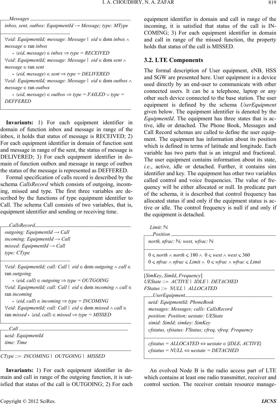 I. A. CHOUDHRY, N. A. ZAFAR 819 »_Messages _______________________ Æinbox, sent, outbox: EquipmentId f Message; type: MType «_______________ ÆAeid: EquipmentId; message: Message | eid e dom inbox ¶ Æmessage e ran inbox Æ • (eid, message) e inbox fi type = RECEIVED ÆAeid: EquipmentId; message: Message | eid e dom sent ¶ Æmessage e ran sent Æ • (eid, message) e sent fi type = DELIVERED ÆAeid: EquipmentId; message: Message | eid e dom outbox ¶ Æmessage e ran outbox Æ • (eid, message) e outbox fi type = FAILED v type = ÆDEFFERED –_____________________________ Invariants: 1) For each equipment identifier in domain of function inbox and message in range of the inbox, it holds that status of message is RECEIVED; 2) For each equipment identifier in domain of function sent and message in range of the sent, the status of message is DELIVERED; 3) For each equipment identifier in do- main of function outbox and message in range of outbox the status of the message is represented as DEFFERED. Formal specification of calls record is described by the schema CallsRecord which consists of outgoing, incom- ing, missed and type. The first three variables are de- scribed by the functions of type equipment identifier to Call. The schema Call consists of two variables, that is, equipment identifier and sending or receiving time. »_CallsRecord______________________ Æoutgoing: EquipmentId f Call Æincoming: EquipmentId f Call Æmissed: EquipmentId f Call Ætype: CType «_______________ ÆAeid: EquipmentId; call: Call | eid e dom outgoing ¶ call e Æran outgoing Æ • (eid, call) e outgoing fi type = OUTGOING ÆAeid: EquipmentId; call: Call | eid e dom incoming ¶ call e Æran incoming Æ • (eid, call) e incoming fi type = INCOMING ÆAeid: EquipmentId; call: Call | eid e dom missed ¶ call e Æran missed • (eid, call) e missed fi type = MISSED –_____________________________ »_Call _________________________ Æueid: EquipmentId Ætime: Time –_____________________________ CType ::= INCOMING | OUTGOING | MISSED Invariants: 1) For each equipment identifier in do- main and call in range of the outgoing function, it is sat- isfied that status of the call is OUTGOING; 2) For each equipment identifier in domain and call in range of the incoming, it is satisfied that status of the call is IN- COMING; 3) For each equipment identifier in domain and call in range of the missed function, the property holds that status of the call is MISSED. 3.2. LTE Components The formal description of User equipment, eNB, HSS and SGW are presented here. User equipment is a device used directly by an end-user to communicate with other connected users. It can be a telephone, laptop or any other such device connected to the base station. The user equipment is defined by the schema UserEquipment given below. The equipment identifier is denoted by the EquipmentId. The equipment has three states that is ac- tive, idle or detached. The Phone Book, Messages and Call Record schemas are called to define the user equip- ment. The equipment has information about its position which is defined in terms of latitude and longitude. Each variable has two parts that is an integral and fractional. The user equipment contains information about its state, i.e., active, idle or detached. Further, it contains sim identifier and key. The equipment has other two variables called control and voice frequencies. The value of fre- quency will be either allocated or null. In predicate part of the schema, it is described that control frequency has allocated status if and only if the equipment status is ac- tive or idle. The control frequency is null if and only if the equipment is detached. Limit: N »_Position ________________________ Ænorth, nfrac: N; west, wfrac: N «_______________ Æ0 ¯ north ¶ north ¯ 180 ¶ 0 ¯ west ¶ west ¯ 360 Æ0 ¯ nfrac ¶ nfrac ¯ Limit ¶ 0 ¯ wfrac ¶ wfrac ¯ Limit –_____________________________ [SimKey, SimId, Frequency] UEState ::= ACTIVE | IDLE | DETACHED FStatus ::= NULL | ALLOCATED »_UserEquipment____________________ Æueid: EquipmentId; PhoneBook Æmessages: Messages; calls: CallsRecord Æposition: Position; uestate: UEState Æsimid: SimId; simkey: SimKey Æcfstatus, vfstatus: FStatus; cfreq, vfreq: Frequency «_______________ Æcfstatus = ALLOCATED ¤ uestate e {IDLE, ACTIVE} Æcfstatus = NULL ¤ uestate = DETACHED –_____________________________ An evolved Node B is the radio access part of LTE which contains at least one radio transmitter, receiver and control section. The receiver contain resource manage- Copyright © 2012 SciRes. IJCNS  I. A. CHOUDHRY, N. A. ZAFAR 820 ment and logic control functions. The evolved Node B is denoted by the schema eNB given below. The schema consists of seven components. The first one node is iden- tifier denoted by NodeId. The next three components are frequencies, namely, total set of frequencies, control and voice frequencies. The next component is a set of equipment connected to the evolved Node B. Finally, two functions for control frequencies and voice frequen- cies are described from a set of frequency to equipment identifier. The node identifier is of type Node. [Node] »_eNB_________________________ Æenb: Node; uequipments: F UserEquipment Æfrequencies; cfrequencies ;vfrequencies: F Frequency Æcalloc; valloc: Frequency f EquipmentId «_______________ Æcfrequencies Î 0 ¶ vfrequencies Î 0 Æcfrequencies I vfrequencies = 0 Æfrequencies = cfrequencies U vfrequencies ÆAue: UserEquipment | uequipments Î 0 Æ • ue e uequipments fi ue . cfreq e cfrequencies ¶ ue . Ævfreq e vfrequencies ÆAf1, f2: Frequency; ei: EquipmentId | (f1, ei) e calloc ¶ (f2, Æei) e calloc • f1 = f2 ÆAf1, f2: Frequency; ei: EquipmentId | (f1, ei) e valloc ¶ (f2, Æei) e valloc • f1 = f2 ÆAfr: Frequency | fr e dom calloc • fr e cfrequencies ÆAfr: Frequency | fr e dom valloc • fr e vfrequencies ÆAue1: EquipmentId | ue1 e ran calloc Æ • Eue2: UserEquipment | ue2 e uequipments • ue1 = ue2 Æ. ueid ÆAue1: EquipmentId | ue1 e ran calloc Æ • Eue2: UserEquipment | ue2 e uequipments • ue1 = ue2 Æ. ueid –____________________________ Invariants: 1) Control and voice frequencies are non- empty; 2) Intersection of control and voice frequencies is an empty set; 3) The union of control and voice frequen- cies is equal to set of total frequencies; 4) The control and voice frequencies of each equipment connected to evolved node are in the set of total frequencies in the node; 5) The control frequency is a one to one function; 6) The voice frequency is a one to one function that is a voice frequency can be assigned to only one equipment; 7) The control frequency in the domain of frequency al- location function to each user equipment, is in the set of control frequencies of evolved node; 8) The voice fre- quency in the domain of frequency allocation function to each user equipment, is in the set of voice frequencies of evolved node; 9) The range of control frequency is subset of set of equipments of evolved node; 10) The range of voice frequency function is sub-set of set of equipments of evolved node. The HSS manages subscription related information and supports the network control layer. It consists of various components some of the important information is given below in schema HSS. The first one component is its identifier. The second one is access having value granted or not denied. The next three components are for storing record about sim identifiers, sim keys and equip- ment identifiers. The relationship between sim identifiers with keys and equipment are also defined. Home location and visitor location registers are represented by hlrs and vlrs respectively which are power set of location register (LR). Three types of networks, GERAN, UTRAN and 2G/3G, are considered in the schema. The sim is de- scribed by the schema sim which consists of sim key, sim’s owner, balance to call, render and other informa- tion. The last one component is added because this sche- ma can be extended in our future work to have more in- formation needed for the definition of sim. [Render] »_Sim__________________________ Æsimkey: SimKey; owner: seq String Æbalance: N; render: Render; otherinfo: seq String –_____________________________ [LR, HId]; Access ::= GRANTED | DENIED RAN ::= GERAN | UTRAN | G23 ; BalLimit: N »_HSS__________________________ Æhid: Hid ; access: Access; sims: SimId f Sim Æsrecord: SimId f EquipmentId; simkeys: F SimKey Æhlrs, vlrs: F LR ; networktype: RAN «_______________ ÆAsid: SimId; sim: Sim | sid e dom sims ¶ sim e ran sims ¶ Æ(sid, sim) e sims Æ • sim . balance ˘ BalLimit fi access = GRANTED ÆAsid: SimId; sim: Sim | sid e dom sims ¶ sim e ran sims ¶ Æ(sid, sim) e sims • sim . balance < BalLimit fi access = ÆDENIED ÆAsid: SimId | sid e dom sims • sid e dom srecord ÆAsid: SimId | sid e dom srecord • sid e dom sims ÆAsid: SimId; sim: Sim | sid e dom sims ¶ sim e ran sims ¶ Æ(sid, sim) e sims • sim . simkey e simkeys ÆAlr: LR • lr e hlrs fi lr ‰ vlrs ¶ lr e vlrs fi lr ‰ hlrs –_____________________________ Invariants: 1) Each sim identifier in the HSS is in the domain of sims function. If the sim balance is more than the minimum limit than permission for call is guaranteed; 2) If the sim balance is less than the minimum required limit then permission for call is not guaranteed; 3) Each sim in the domain of sim function is in the domain of sim-equipment function; 4) Each sim in the domain of sim-equipment function is in the domain of sims function; Copyright © 2012 SciRes. IJCNS  I. A. CHOUDHRY, N. A. ZAFAR 821 5) Each sim key in the sim record function is in the HSS; 6) The intersection of sets, home location and visitors location registers, is empty. The primary functionality of Serving Gateway (SGW) is to manage user mobility and act as a segregation point between the radio access network and the other core networks. The SGW maintains data movement between evolved nodes and the PDN Gateway. In a functional point of view, SGW is a termination point of the packet data network interface. Considering functionality of SGW, formal specification of SGW is given below by using the schema SGW. The schema consists of four components, namely, identifier, internet protocol, data and networks. The data is defined as a basic set type. The radio access network types are same as defined above in the definition of HSS schema. In the predicate part of the schema, it is stated that the data packet is sent towards a network based on the request of sender. [Data]; IP ::= IP 1 | IP2 | IP3 »_SGW_________________________ Æsgw: seq N; iprotocol: IP; data: Data; network : RAN «_______________ Æiprotocol = IP1 fi network = GERAN Æiprotocol = IP2 fi network = UTRAN Æiprotocol = IP3 fi network = G23 –_____________________________ The Mobility Management Entity (MME) is the key control node for the Long Term Evolution network. The primary functionality of MME is monitoring tracking and paging procedure for idle mode user equipment. It is in- volved in activation and deactivation processes and is responsible for choosing the SGW for user equipment at the initial process. It is responsible for security issues including authentication of the user by interacting with the HSS. It verifies authorization of user equipment to site on the service provider and enforces the equipment roaming restrictions. Furthermore, the MME provides the control function for mobility between Long Term Evolu- tion and other access networks. Formal specification of Mobility Management Entity is given below using the schema MME. The schema con- sists of five components, namely, evolved nodes, home subscriber servers, serving gateways, verification and request. The formal definitions of the components are already given in terms of schemas. In MME schema, evolved nodes, home subscriber servers and serving gate- ways are assumed as power sets. Similar to above, all sets are assumed as finite collections of the components. Request has two values either success or failure. Simi- larly verification is either done or rejected. Request ::= SUCCESS | FAILURE Verification ::= VERIFIED | REJECTED »_MME_________________________ Æenbs: F eNB; hsss: F HSS; sgws: F SGW Æverification: Verification; request: Request «_______________ ÆAenb: eNB | enb e enbs Æ • Aue: UserEquipment | ue e enb . uequipments Æ • Ehss: HSS | hss e hsss Æ • Esid: SimId; uei: EquipmentId | (sid, uei) e hss . srecord Æ • ue . ueid = uei ¶ ue . simid = sid ÆAenb: eNB | enb e enbs Æ • Aue: UserEquipment | ue e enb . uequipments Æ • Ehss: HSS | hss e hsss Æ • Esk: SimKey | sk e hss . simkeys • ue . simkey = sk ÆAenb: eNB | enb e enbs Æ • Aue: UserEquipment | ue e enb . uequipments Æ • verification = VERIFIED fi request = SUCCESS ÆAenb: eNB | enb e enbs Æ • Aue: UserEquipment | ue e enb . uequipments Æ • verification = REJECTED fi request = FAILURE –_____________________________ Invariants: 1) For each evolved node and for each user equipment in the node there exists home subscriber server which contains the sim identifier of the equipment; 2) For an evolved node and for each equipment in the node there exists home subscriber server containing sim identifier of the equipment; 3) For each user equipment, if identity is verified, it is successful; 4) For an equip- ment, if the identity is not verified then it is a failure. Finally, formal specification of LTE is given below using LTE schema which consists of five components, namely, set of evolved nodes, set of home subscriber servers, set of serving gateways, set of mobile manage- ment entities and network. The components definitions are given in first part and invariants are defined in the second part of the schema. »_LTE__________________________ ÆeNBS: F eNB; hSSS: F HSS ÆsGWS: F SGW ; mMES: F MME ; networks: RAN «_______________ ÆAmm: MME | mm e mMES • Aenb: eNB | enb e mm . enbs Æ• enb e eNBS ÆAmm: MME | mm e mMES • Ahs: HSS | hs e mm . hsss Æ• hs e hSSS ÆAmm: MME | mm e mMES • Asg: SGW | sg e mm . sgws Æ• sg e sGWS –_____________________________ Invariants: 1) For each mobile management entity and for every evolved node, the node is in the LTE sys- tem; 2) For each mobile management entity and for every Copyright © 2012 SciRes. IJCNS  I. A. CHOUDHRY, N. A. ZAFAR Copyright © 2012 SciRes. IJCNS 822 There exist various tools for analyzing Z specification, Z/Eves is one of the powerful tools used in this research for analyzing the formal specification of long term evo- lution communications system. A snapshot of the part of the specification analysis is provided in Figure 2. First column on the left of the figure shows status of the syn- tax checking and the second column represents the proof correctness of the specification. The symbol “Y” stands that specification is correct syntactically and proof is also correct. The symbol “N” is used that errors exist which needs to be fixed by further analysis. Formal specifica- tion of our systems is fully analyzed to be correct and hence “N” does not appear in the figure. All the schemas are checked to be correct in syntax and has a correct proof. home subscriber server, the server is in the LTE system; 3) For each mobile management entity and for every serving gateway, the gateway is in the LTE system. 4. Model Analysis Formal analysis of the specification is provided here in this section. Since there does not exist any computer tool which may assure about complete correctness of a formal model, therefore, even the specification is well-written, it may contain potential errors. Hence, an art of writing specification does not provide guarantee about correct- ness of a system. However, if the specification is analyz- ed and validated with the rigorous computer tools, it certainly improves confidence by identifying errors if exists. Summary of the results is presented in Table 1 given Figure 2. Model analysis using Z/Eves tool. Table 1. Results of model analysis. Schema Name Syntax Type Check Domain Check Reduction Proof Person Y Y NA Y PhoneBook Y Y NA Y Message Y Y NA Y Messages Y Y NA Y Call Y Y NA Y CallsRecord Y Y NA Y Position Y Y NA Y UserEquipment Y Y NA Y eNB Y Y NA Y Sim Y Y NA Y HSS Y Y NA Y SGW Y Y NA Y MME Y Y NA Y LTE Y Y NA Y 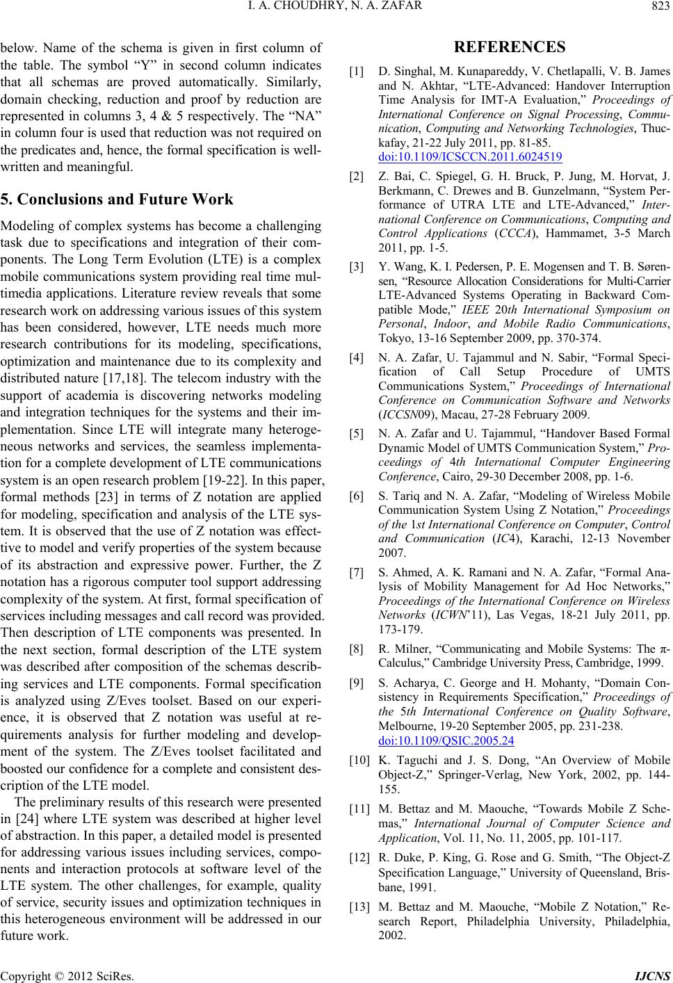 I. A. CHOUDHRY, N. A. ZAFAR 823 below. Name of the schema is given in first column of the table. The symbol “Y” in second column indicates that all schemas are proved automatically. Similarly, domain checking, reduction and proof by reduction are represented in columns 3, 4 & 5 respectively. The “NA” in column four is used that reduction was not required on the predicates and, hence, the formal specification is well- written and meaningful. 5. Conclusions and Future Work Modeling of complex systems has become a challenging task due to specifications and integration of their com- ponents. The Long Term Evolution (LTE) is a complex mobile communications system providing real time mul- timedia applications. Literature review reveals that some research work on addressing various issues of this system has been considered, however, LTE needs much more research contributions for its modeling, specifications, optimization and maintenance due to its complexity and distributed nature [17,18]. The telecom industry with the support of academia is discovering networks modeling and integration techniques for the systems and their im- plementation. Since LTE will integrate many heteroge- neous networks and services, the seamless implementa- tion for a complete development of LTE communications system is an open research problem [19-22]. In this paper, formal methods [23] in terms of Z notation are applied for modeling, specification and analysis of the LTE sys- tem. It is observed that the use of Z notation was effect- tive to model and verify properties of the system because of its abstraction and expressive power. Further, the Z notation has a rigorous computer tool support addressing complexity of the system. At first, formal specification of services including messages and call record was provided. Then description of LTE components was presented. In the next section, formal description of the LTE system was described after composition of the schemas describ- ing services and LTE components. Formal specification is analyzed using Z/Eves toolset. Based on our experi- ence, it is observed that Z notation was useful at re- quirements analysis for further modeling and develop- ment of the system. The Z/Eves toolset facilitated and boosted our confidence for a complete and consistent des- cription of the LTE model. The preliminary results of this research were presented in [24] where LTE system was described at higher level of abstraction. In this paper, a detailed model is presented for addressing various issues including services, compo- nents and interaction protocols at software level of the LTE system. The other challenges, for example, quality of service, security issues and optimization techniques in this heterogeneous environment will be addressed in our future work. REFERENCES [1] D. Singhal, M. Kunapareddy, V. Chetlapalli, V. B. James and N. Akhtar, “LTE-Advanced: Handover Interruption Time Analysis for IMT-A Evaluation,” Proceedings of International Conference on Signal Processing, Commu- nication, Computing and Networking Technologies, Thuc- kafay, 21-22 July 2011, pp. 81-85. doi:10.1109/ICSCCN.2011.6024519 [2] Z. Bai, C. Spiegel, G. H. Bruck, P. Jung, M. Horvat, J. Berkmann, C. Drewes and B. Gunzelmann, “System Per- formance of UTRA LTE and LTE-Advanced,” Inter- national Conference on Communications, Computing and Control Applications (CCCA), Hammamet, 3-5 March 2011, pp. 1-5. [3] Y. Wang, K. I. Pedersen, P. E. Mogensen and T. B. Søren- sen, “Resource Allocation Considerations for Multi-Carrier LTE-Advanced Systems Operating in Backward Com- patible Mode,” IEEE 20th International Symposium on Personal, Indoor, and Mobile Radio Communications, Tokyo, 13-16 September 2009, pp. 370-374. [4] N. A. Zafar, U. Tajammul and N. Sabir, “Formal Speci- fication of Call Setup Procedure of UMTS Communications System,” Proceedings of International Conference on Communication Software and Networks (ICCSN09), Macau, 27-28 February 2009. [5] N. A. Zafar and U. Tajammul, “Handover Based Formal Dynamic Model of UMTS Communication System,” Pro- ceedings of 4th International Computer Engineering Conference, Cairo, 29-30 December 2008, pp. 1-6. [6] S. Tariq and N. A. Zafar, “Modeling of Wireless Mobile Communication System Using Z Notation,” Proceedings of the 1st International Conference on Computer, Control and Communication (IC4), Karachi, 12-13 November 2007. [7] S. Ahmed, A. K. Ramani and N. A. Zafar, “Formal Ana- lysis of Mobility Management for Ad Hoc Networks,” Proceedings of the International Conference on Wireless Networks (ICWN’11), Las Vegas, 18-21 July 2011, pp. 173-179. [8] R. Milner, “Communicating and Mobile Systems: The π- Calculus,” Cambridge University Press, Cambridge, 1999. [9] S. Acharya, C. George and H. Mohanty, “Domain Con- sistency in Requirements Specification,” Proceedings of the 5th International Conference on Quality Software, Melbourne, 19-20 September 2005, pp. 231-238. doi:10.1109/QSIC.2005.24 [10] K. Taguchi and J. S. Dong, “An Overview of Mobile Object-Z,” Springer-Verlag, New York, 2002, pp. 144- 155. [11] M. Bettaz and M. Maouche, “Towards Mobile Z Sche- mas,” International Journal of Computer Science and Application, Vol. 11, No. 11, 2005, pp. 101-117. [12] R. Duke, P. King, G. Rose and G. Smith, “The Object-Z Specification Language,” University of Queensland, Bris- bane, 1991. [13] M. Bettaz and M. Maouche, “Mobile Z Notation,” Re- search Report, Philadelphia University, Philadelphia, 2002. Copyright © 2012 SciRes. IJCNS  I. A. CHOUDHRY, N. A. ZAFAR 824 [14] 3GPP TR 25.913, “Requirements for Evolved UTRA and Evolved UTRAN,” V7.3.0 2006. [15] 3GPP TS 23.401, “GPRS Enhancements on EUTRAN Access,” 2007. http://www.3gpp.org [16] Alcatel Lucent, “The LTE Network Architecture—A Com- prehensive Tutorial,” 2009. www.alcatel-lucent.com [17] M. M. A. Airchinnigh and M. Butler, “Service Speci- fication Using Z,” Technical Report, University of South- ampton, Southampton, 1993. http://eprints.soton.ac.uk/253693 [18] R. Cam and S. Vuong, “A Formal Specification in LOTOS, of a Simplified Cellular Mobile Communication System,” Formal Description Techniques-II (FORTE’89), North- Holland Publishing Co., Amsterdam, 1990, pp. 485-499. [19] L. Chen, et al., “System Level Simulation Methodology and Platform for Mobile Cellular Systems,” IEEE Com- munication Magazine, Vol. 49, No. 7, pp. 148-155. 2011. [20] K. Doppler, “Device-To-Device Communication as an Underlay to LTE Advanced Networks,” IEEE Commu- nication Magazine, Vol. 47, No. 12, pp. 42-49. [21] Y. Sun, “Editorial Advanced Signal Processing for Wire- less and Mobile Communications,” IET Signal Processing, Vol. 3, No. 6, 2009, pp. 431-432. 109. [22] J. M. Wing, “A Specifier’s Introduction to Formal Me- thods,” IEEE Computer, Vol. 23, No. 9, 1990, pp. 8-24. [23] H. Luo, et al., “Quality Driven Cross Layer Optimized Video Delivery over LTE,” IEEE Communication Magazine, Vol. 48, No. 2, 2010, pp. 102- [24] I. A. Choudhry, N. A. Zafar and M. Zahrani, “Validating Statistics of Long Term Evolution Mobile Communi- cations System,” Proceedings of the 2012 International Conference on Modeling, Simulation and Visualization Methods, Las Vegas, 16-19 July 2012, pp. 201-206. Copyright © 2012 SciRes. IJCNS |