Paper Menu >>
Journal Menu >>
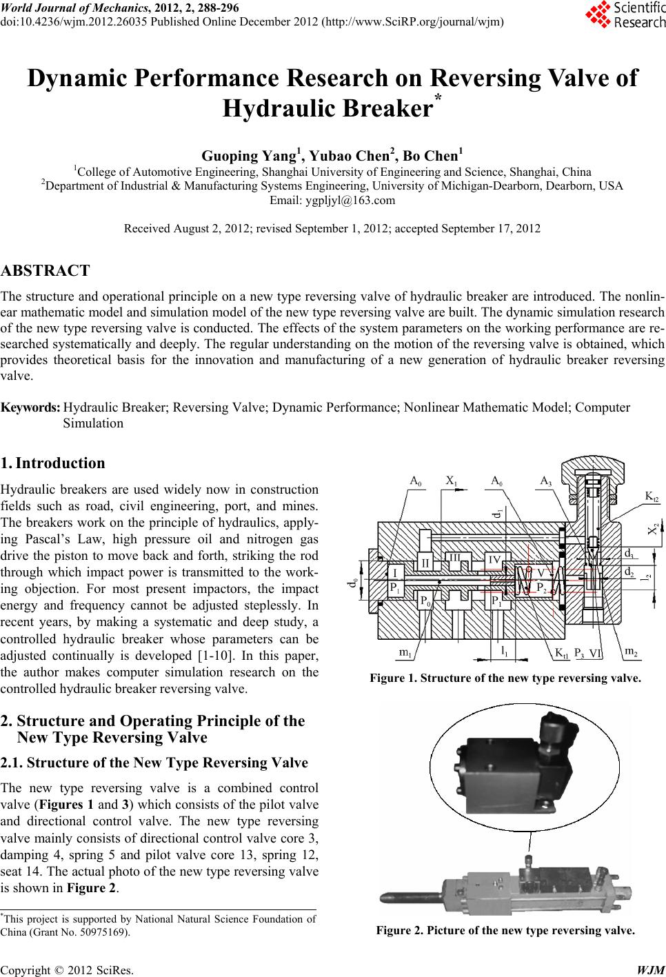 World Journal of Mechanics, 2012, 2, 288-296 doi:10.4236/wjm.2012.26035 Published Online December 2012 (http://www.SciRP.org/journal/wjm) Copyright © 2012 SciRes. WJM Dynamic Performance Research on Reversing Valve of Hydraulic Breaker* Guoping Yang1, Yubao Chen2, Bo Chen1 1College of Automotive Engineering, Shanghai University of Engineering and Science, Shanghai, China 2Department of Industrial & Manufacturing Systems Engineering, University of Michigan-Dearborn, Dearborn, USA Email: ygpljyl@163.com Received August 2, 2012; revised September 1, 2012; accepted September 17, 2012 ABSTRACT The structure and operational principle on a new type reversing valve of hydraulic breaker are introduced. The nonlin- ear mathematic model and simulation model of the new type reversing valve are built. The dynamic simulation research of the new type reversing valve is conducted. The effects of the system parameters on the working performance are re- searched systematically and deeply. The regular understanding on the motion of the reversing valve is obtained, which provides theoretical basis for the innovation and manufacturing of a new generation of hydraulic breaker reversing valve. Keywords: Hydraulic Breaker; Reversing Valve; Dynamic Performance; Nonlinear Mathematic Model; Computer Simulation 1. Introduction Hydraulic breakers are used widely now in construction fields such as road, civil engineering, port, and mines. The breakers work on the principle of hydraulics, apply- ing Pascal’s Law, high pressure oil and nitrogen gas drive the piston to move back and forth, striking the rod through which impact power is transmitted to the work- ing objection. For most present impactors, the impact energy and frequency cannot be adjusted steplessly. In recent years, by making a systematic and deep study, a controlled hydraulic breaker whose parameters can be adjusted continually is developed [1-10]. In this paper, the author makes computer simulation research on the controlled hydraulic breaker reversing valve. 2. Structure and Operating Principle of the New Type Reversing Valve 2.1. Structure of the New Type Reversing Valve The new type reversing valve is a combined control valve (Figures 1 and 3) which consists of the pilot valve and directional control valve. The new type reversing valve mainly consists of directional control valve core 3, damping 4, spring 5 and pilot valve core 13, spring 12, seat 14. The actual photo of the new type reversing valve is shown in Figure 2. Figure 1. Structure of the new type reversing valve. Figure 2. Picture of the new type reversing valve. *This project is supported by National Natural Science Foundation o f China (Grant No. 50975169). 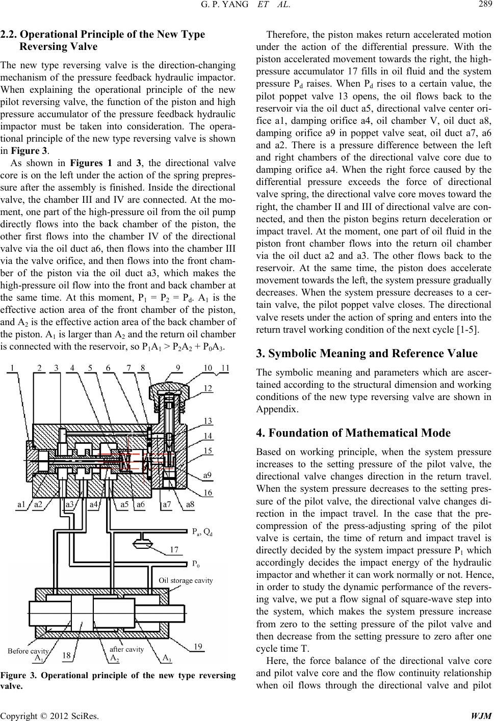 G. P. YANG ET AL. Copyright © 2012 SciRes. WJM 289 2.2. Operational Principle of the New Type Reversing Valve The new type reversing valve is the direction-changing mechanism of the pressure feedback hydraulic impactor. When explaining the operational principle of the new pilot reversing valve, the function of the piston and high pressure accumulator of the pressure feedback hydraulic impactor must be taken into consideration. The opera- tional principle of the new type reversing valve is shown in Figure 3. As shown in Figures 1 and 3, the directional valve core is on the left under the action of the spring prepres- sure after the assembly is finished. Inside the directional valve, the chamber III and IV are connected. At the mo- ment, one part of the high-pressure oil from the oil pump directly flows into the back chamber of the piston, the other first flows into the chamber IV of the directional valve via the oil duct a6, then flows into the chamber III via the valve orifice, and then flows into the front cham- ber of the piston via the oil duct a3, which makes the high-pressure oil flow into the front and back chamber at the same time. At this moment, P1 = P2 = Pd. A1 is the effective action area of the front chamber of the piston, and A2 is the effective action area of the back chamber of the piston. A1 is larger than A2 and the return oil chamber is connected with the reservoir, so P1A1 > P2A2 + P0A3. Figure 3. Operational principle of the new type reversing valve. Therefore, the piston makes return accelerated motion under the action of the differential pressure. With the piston accelerated movement towards the right, the high- pressure accumulator 17 fills in oil fluid and the system pressure Pd raises. When Pd rises to a certain value, the pilot poppet valve 13 opens, the oil flows back to the reservoir via the oil duct a5, directional valve center ori- fice a1, damping orifice a4, oil chamber V, oil duct a8, damping orifice a9 in poppet valve seat, oil duct a7, a6 and a2. There is a pressure difference between the left and right chambers of the directional valve core due to damping orifice a4. When the right force caused by the differential pressure exceeds the force of directional valve spring, the directional valve core moves toward the right, the chamber II and III of directional valve are con- nected, and then the piston begins return deceleration or impact travel. At the moment, one part of oil fluid in the piston front chamber flows into the return oil chamber via the oil duct a2 and a3. The other flows back to the reservoir. At the same time, the piston does accelerate movement towards the left, the system pressure gradually decreases. When the system pressure decreases to a cer- tain valve, the pilot poppet valve closes. The directional valve resets under the action of spring and enters into the return travel working condition of the next cycle [1-5]. 3. Symbolic Meaning and Reference Value The symbolic meaning and parameters which are ascer- tained according to the structural dimension and working conditions of the new type reversing valve are shown in Appendix. 4. Foundation of Mathematical Mode Based on working principle, when the system pressure increases to the setting pressure of the pilot valve, the directional valve changes direction in the return travel. When the system pressure decreases to the setting pres- sure of the pilot valve, the directional valve changes di- rection in the impact travel. In the case that the pre- compression of the press-adjusting spring of the pilot valve is certain, the time of return and impact travel is directly decided by the system impact pressure P1 which accordingly decides the impact energy of the hydraulic impactor and whether it can work normally or not. Hence, in order to study the dynamic performance of the revers- ing valve, we put a flow signal of square-wave step into the system, which makes the system pressure increase from zero to the setting pressure of the pilot valve and then decrease from the setting pressure to zero after one cycle time T. Here, the force balance of the directional valve core and pilot valve core and the flow continuity relationship when oil flows through the directional valve and pilot 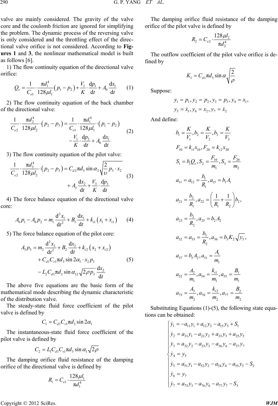 G. P. YANG ET AL. Copyright © 2012 SciRes. WJM 290 valve are mainly considered. The gravity of the valve core and the coulomb friction are ignored for simplifying the problem. The dynamic process of the reversing valve is only considered and the throttling effect of the direc- tional valve orifice is not considered. According to Fig- ures 1 and 3, the nonlinear mathematical model is built as follows [6]. 1) The flow continuity equation of the directional valve orifice: 4 1111 12 0 11 πdd 1 128d d s e dVpx QppA Cl Ktt (1) 2) The flow continuity equation of the back chamber of the directional valve: 44 21 23 12 22 11 12 1 0 ππ 11 128 128 dd dd ee dd pp pp Cl Cl Vp x A Kt t (2) 3) The flow continuity equation of the pilot valve: 4 2 2323 232 22 33 2 3 π 12 πsin 128 d d dd d e dpp Cdpx Cl Vp x AtKt (3) 4) The force balance equation of the directional valve core: 2 11 0102111 11 2 dd d dtt xx A pAp mBkxx t t (4) 5) The force balance equation of the pilot core: 2 22 33222 22 2 11 31 23 2 213 123 dd d d πsin 2 d πsin 2d tt dv d xx A pmB kxx t t CC dxp x LC dpt (5) The above five equations are the basic form of the mathematical mode describing the dynamic characteristic of the distribution valve. The steady-state fluid force coefficient of the pilot valve is defined by 1113 1 πsin 2 dv CCCd The instantaneous-state fluid force coefficient of the pilot valve is defined by 21113 1 πsin 2 dv CLCCd The damping orifice fluid resistance of the damping orifice of the directional valve is defined by 1 11 4 1 128 π e l RC d The damping orifice fluid resistance of the damping orifice of the pilot valve is defined by 2 22 4 2 128 π e l RC d The outflow coefficient of the pilot valve orifice is de- fined by 113 2 πsin d KCd Suppose: 112 23341 516 27 2 ,,,, ,, ypypypyx yxy xyx And define: 12 3 123 101 1020220 10 20 11 23 12 1 11121511 1 2 21 222 112 2 23252 2 2 3 3233363 23 2 1 373 251 1 1 21 52 54 55 11 ,, , ,, , 11 ,, , ,, , ,, tt s t KKK bb b VVV FkxFkx FF SbQS S mm b aa abA R b aa b RRR b aabA R b aa abKy R A abAam k AB aaa mmm 1 32 2 73 76 77 222 ,, t Ak B aaa mmm Substituting Equations (1)-(5), the following state equa- tions can be obtained: 11111221551 221 1222233255 332 233336 637 7 45 551152 25445552 67 77337667773 y ayayayS yayayayay yayayayay yy y ayayayayS yy yayayayS  G. P. YANG ET AL. Copyright © 2012 SciRes. WJM 291 5. Simulation Results and Analysis A flow signal of square-wave step is input into the dis- tribution valve. The system pressure will dynamically rise from zero to the setting pressure of the pilot valve and then the system pressure decreases from the setting pressure to zero after one cycle T. The actual displace- ment response of the pilot valve and the directional valve is shown in Figure 4. The response consists of three parts, the first part is the response of positive step, the second part is steady-state area and the third part is the response of negative step. In the region of positive step response, tyz is the delay time when the pilot valve opens or the directional valve changes direction, trz is the peak time when the pilot valve opens or the directional valve changes direction, tsz is the transition time when the pilot valve opens or the directional valve changes direction. In the region of negative step response, tyf is the delay time when the pilot valve closes or the directional valve resets, trz is the peak time when the pilot valve closes or the di- rectional valve resets, tsz is the transition time when the pilot valve closes or the directional valve resets [7]. In the process of the negative step response, the pilot valve core gets the mechanical limit of the pilot valve seat and the directional valve core gets the mechanical limit of the directional valve body, so the overshoot phe- nomenon does not appear and one or two tiny rebound waves which do not affect the characteristic of the dis- tribution valve may only appear. Thus, the positive step response is only studied. Videlicet, the dynamic charac- teristic when the pilot valve opens or the directional valve changes direction in the return travel is studied. The simulation results are as follows. Figure 4. Step response curves of the distribution valve. 1) The dynamic characteristics of the valve at the dif- ferent setting pressure and the same step flow. Figures 5(a) and (b) show the dynamic response curve when the setting pressure P* is 11 MPa and 15 MPa, the initial oil pressure P0 is 0.8 MPa, the step flow ΔQ is 40 l/min. The conclusions are as follows: a) The valve is stable under the conditions of the ex- isting structural parameters. The stability of the pressure value and the directional valve core displacement X1 is good. The oscillation of the pilot valve is convergent. The amplitude increases with the decrease of the setting pressure. When P* is 11 MPa, the amplitude tends equi- valent. This shows that considering from the point of the dynamic characteristic; its performance will be degra- dated when the distribution valve works under the condi- tion which is far away from the designed situation. b) The peak value of P1 decreases with the decrease of the setting pressure, but its overshoot ΔP1 is nearly con- stant which shows the pressure overshoot has nothing to do with the steady-state pressure. c) Under the current parameters, ΔP1 is 12 MPa, the peak time trz is 0.003 s to 0. 004 s, the transition process time tsz is about 0.03 s, which shows that the time-do- main dynamic quality index of the valve is satisfying. 2) The dynamic characteristics at the same setting pressure, the same step flow and the different initial con- ditions. (a) (b) Figure 5. Simulation curves one.  G. P. YANG ET AL. Copyright © 2012 SciRes. WJM 292 Figures 6(a) and (b) show the dynamic response curve when the initial oil pressure P0 is respectively 0.2 MPa and 0.6 MPa, the setting pressure P* is 14 MPa, the step flow ΔQ is 40 l/min. It is obvious in Figure 6 that the valve is stable no matter the initial conditions, the exces- sive pressure adjustment ΔP1 doesn’t change with the initial conditions, the peak and rise time of P1 basically does not change with the initial conditions. 3) The dynamic characteristics at the same setting pres- sure and different step flow. The response curves (Figures 7(a)-(c)) of the inlet port oil pressure, the pressure P* is 15 MPa and the step flow ΔQ is 40, 25, 15 l/min. By comparison, the conclu- sions are as follows: a) The pressure overshoot ΔP1 is obviously affected by the step flow. The smaller the overflow, the smaller the overshoot. b) The pressure rise time, peak time and transition process time increase with the decrease of the overflow quantity. c) The changes of the overflow quantity within a cer- tain range nearly affect the stability of the valve. 4) Effects of the directional valve core damping orifice on the distribution valve dynamic characteristics. The curves shown in Figures 8(a)-(c) are respectively the characteristic curves of the pilot valve core and direc- tional valve core displacement when the diameter of the directional valve damping orifice is 0.15 cm (the thick curve in Figure), 0.12 cm (the middle-thick curve) (a) (b) Figure 6. Simulation curves two. (a) (b) (c) Figure 7. Simulation curves three. and 0.10 cm (the thin curve) under the conditions that the initial oil pressure is 0.8 MPa, the setting pressure is 15 MPa and the step flow ΔQ is 40 l/min. Figure 8 shows: a) d1 has a great effect on the excessive pressure ad- justrent. The smaller d1, the larger ΔP1. The response will be slower when d1 minifies. b) When d1 changes in a small area, it won’t obviously affect the stability of the valve. When d1 minifies, the pilot valve core will close for a long time. If d1 increases appropriately, the ΔP1 will decrease and the stability  G. P. YANG ET AL. Copyright © 2012 SciRes. WJM 293 (a) (b) (c) Figure 8. Simulation curves four. won’t get worse. 5) Changes of damping orifice of the pilot valve seat. The curves shown in Figures 9(a)-(c) are respect- tively the characteristic curves of the inlet port oil pre- ssure, the pilot valve core and directional valve core displacement under the conditions that the initial oil pressure is 0.8 MPa, the setting pressure is 15 MPa and the step flow ΔQ is 40 l/min when the diameters of the pilot valve damping orifice is respectively 0.15, 0.12 and 0.10 cm. It is clear in Figure 9 that d2 has an obvious effect on the dynamic characteristics of the valve. When d2 de- (a) (b) (c) Figure 9. Simulation curves five. creases to 0.10 cm, the oscillation phenomenon will hardly occur. However, ΔP1 will correspondingly in- crease and the time of pressure peak will also have a little increase. The above discussion shows that dl and d2 not only af- fect the dynamic characteristics of the valve, but also have a certain match. Selecting d1 and d2 reasonably, the less overshoot of pressure can be gotten and the oscilla- tion of the pilot valve core doesn’t appear. Figure 10 shows that the dynamic characteristics of the valve are satisfactory when d1 is 0.1 cm, d2 is 0.10 cm and the  G. P. YANG ET AL. Copyright © 2012 SciRes. WJM 294 Figure 10. Simulation curves six. other conditions are the same as Figures 8 and 9. 6) Effects of duct stiffness on the valve dynamic char- acteristics. The duct’s stiffness depends on the elastic modulus of the fluid and piple. When the fluid modulus βe is 1.2 × 10⁸ N/m2, 9 × 10⁹ N/m2, 7 × 10⁹ N/m2 and the piple be- tween the pump and the distribution valve is flexible, the fluid capacitance of the piple CC is respectively 0.067, 0.114 and 0.199. The curves shown in Figures 11(a)-(c) are respectively the response curves of the inlet port oil pressure, the pilot valve core and directional valve core displacement under the conditions that the initial oil pressure P0 is 0.8 MPa, the setting pressure P* is 15 MPa and the step flow ΔQ is 40 l/min when CC is respectively 0.067, 0.144 and 0.199. The simulation results show: a) With the increase of CC, the vibration amplitude of the pilot valve falls. The excessive pressure adjustment ΔP1 falls drastically but the transition time becomes longer, which is caused by the falling of the pipe’s stiff- ness after the increase of fluid capacitance. b) Flexible pipes can absorb the shock wave but the use of the flexible pipes will reduce the sensitivity of the valve, which must be considered in practical use. 7) Effects of the spring stiffness on the dynamic char- acteristics of valve. The results of digital simulation show: a) The balance spring stiffness Kt1 of the directional valve hardly affect the dynamic performance of the valve. Thus, the selection of Kt1 is mainly in accordance with the static performance requirements (meeting the con- stant pressure accuracy). b) The balance spring stiffness Kt2 of the pilot valve has a certain effect on the dynamic characteristics of the valve. With the falling of Kt2, the stability of the pilot core will be a little worse. Thus, the increase of Kt2 is good for the improvement of the stability of the pilot valve, but the effect is more inapparent than the effect caused by reducing the diameter of damping orifice of the pilot valve seat. In addition, considering from the requirements of improving the static performance, Kt2 (a) (b) (c) Figure 11. Simulation curves seven. should be reduced in order to improve regulation preci- sion. Therefore, the static performance is the main basis for selecting Kt2. The curves on the excessive pressure adjustment ΔP1, peak time tr and transition process time ts change with the parameters are shown in Figures 12 and 14 according to the simulation results. It is shown in Figure 12 that ΔP1 increases with the falling of d1 and d2. It is shown in Fig- ure 13 that the peak time tr decreases with the increase of d1; the change of tr is slow when d1 increases to a certain  G. P. YANG ET AL. Copyright © 2012 SciRes. WJM 295 value, then d1 increases slightly; the peak time ts de- creases with the increase of d1; when d1 is 0.001, ts is the smallest; when d1 continues to increase, ts will increase. It is shown in Figure 14 that the variational trend of the peak time tr with d2 is the same as that of d1, but the change of tr is a little slow. Figure 12. Influence of the changes of d1 and d2 on ΔP1. Figure 13. Influence of the changes of d1 on the response time. Figure 14. Influence of the changes of d2 on the response time. 6. Conclusions Through the above analysis, the conclusions are as fol- lows: 1) When the diameter of the directional valve damping orifice decreases, the pressure overshoot and peak time will increase. 2) The changes of the setting pressure P and the mass of the directional valve core and the directional valve right chamber volume V have little influence on the dy- namic quality. 4) The pipeline volume has much influence on the dy- namic quality. 5) To conclude the above, the curves of the distribu- tion valve in the transitional process show that the vibra- tion of the pilot valve affects the commutation, which causes the distribution valve to vibrate. 6) The balance spring stiffness of the directional valve and the balance spring stiffness of the pilot valve can be decided by the static characteristics of the valve. REFERENCES [1] G. P. Yang and C. P. Liang, “A Research on the New Hydraulic Impactor Control System,” 2010 International Conference on Measuring Technology and Mechatronics Automation, Changsha, 13-14 March 2010, pp. 291-293. [2] G. P. Yang, L. H. Chen and H. Huang, “The Research of a Full Hydraulic Pressure Hydraulic Impactor with Strike Energy and Frequency Adjusted Independently,” The 6th International Conference on Fluid Power Transmission and Control, Hangzhou, 1-5 September 2005, pp. 262- 265. [3] G. P. Yang, “Research of a Full Hydraulic Pressure Hy- draulic Impactor with Strike Energy and Frequency Ad- justed Independently,” Journal of Hunan University of Science & Technology (Natural Science Edition), Vol. 21, No. 1, 2006, pp. 25-28. [4] G. P. Yang, “Research on Design Theory on the Return Oil Chamber of a New Hydraulic Impactor,” China Jour- nal of Highway and Transport, Vol. 15, No. 1, 2002, pp. 113-115. [5] X. B. Yang and G. P. Yang, “The Research of a Pressure Feedback Full Hydraulic Pressure Hydraulic Impactor with Strike Energy and Frequency Adjusted Independ- ently,” China Mechanical Engineering, Vol. 13, No. 23, 2002, pp. 2044-2047. [6] G. P. Yang, “Research on Computer Simulation for a New Pilot Type Hydraulic Impactor System,” Mechanical Science and Technolgy, Vol. 25, No. 2, 2006, pp. 233- 237. [7] G. P. Yang, F. L. Zhu and G. J. Long, “Research on De- sign Theory on the Return Oil Chamber of a New Hy- draulic Impactor,” China Mechanical Engineering, No. 12, 2003, pp. 1062-1065. [8] G. P. Yang, J. H. Gao and B. Chen, “Computer Simula- tion of Controlled Hydraulic Impactor System,” Ad- 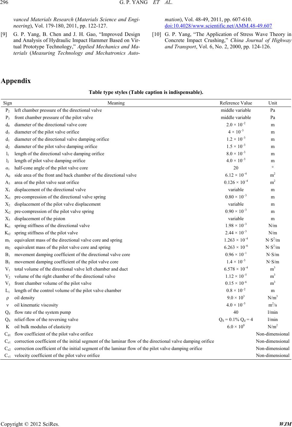 G. P. YANG ET AL. Copyright © 2012 SciRes. WJM 296 vanced Materials Research (Materials Science and Engi- neering), Vol. 179-180, 2011, pp. 122-127. [9] G. P. Yang, B. Chen and J. H. Gao, “Improved Design and Analysis of Hydraulic Impact Hammer Based on Vir- tual Prototype Technology,” Applied Mechanics and Ma- terials (Measuring Technology and Mechatronics Auto- mation), Vol. 48-49, 2011, pp. 607-610. doi:10.4028/www.scientific.net/AMM.48-49.607 [10] G. P. Yang, “The Application of Stress Wave Theory in Concrete Impact Crushing,” China Journal of Highway and Transport, Vol. 6, No. 2, 2000, pp. 124-126. Appendix Table type styles (Table c aption is indispensable). Sign Meaning Reference Value Unit P2 left chamber pressure of the directional valve middle variable Pa P3 front chamber pressure of the pilot valve middle variable Pa d0 diameter of the directional valve core 2.0 × 10⁻² m d3 diameter of the pilot valve orifice 4 × 10⁻³ m d1 diameter of the directional valve damping orifice 1.2 × 10⁻³ m d2 diameter of the pilot valve damping orifice 1.5 × 10⁻³ m l1 length of the directional valve damping orifice 8.0 × 10⁻³ m l2 length of pilot valve damping orifice 4.0 × 10⁻³ m α1 half-cone angle of the pilot valve core 20 ° A0 side area of the front and back chamber of the directional valve 6.12 × 10⁻⁴ m 2 A3 area of the pilot valve seat orifice 0.126 × 10⁻⁴ m 2 X1 displacement of the directional valve variable m Xt1 pre-compression of the directional valve spring 0.80 × 10–3 m X2 displacement of the pilot valve displacement variable m Xt2 pre-compression of the pilot valve spring 0.90 × 10–3 m X3 displacement of the piston variable m Kt1 spring stiffness of the directional valve 1.98 × 10⁻³ N/m Kt2 spring stiffness of the pilot valve 2.44 × 10⁻³ N/m m1 equivalent mass of the directional valve core and spring 1.263 × 10⁻⁴ N·S2/m m2 equivalent mass of the pilot valve core and spring 6.263 × 10⁻⁶ N·S2/m B1 movement damping coefficient of the directional valve core 0.96 × 10⁻¹ N·S/m B2 movement damping coefficient of the pilot valve core 1.4 × 10⁻³ N·S/m V1 total volume of the directional valve left chamber and duct 6.578 × 10⁻⁴ m 3 V2 volume of the right chamber of the directional valve 1.12 × 10⁻⁵ m 3 V3 front chamber volume of the pilot valve 0.15 × 10⁻⁶ m 3 L1 length of the control volume of the pilot valve chamber 0.8 × 10⁻² m ρ oil density 9.0 × 10³ N/m3 ν oil kinematic viscosity 4.0 × 10⁻⁵ m 2/s Qd flow rate of the system pump 40 l/min QS relief-flow of the reversing valve QS = 0.1% Qd = 4 l/min K oil bulk modulus of elasticity 6.0 × 10⁸ N/m2 Cd1 flow coefficient of the pilot valve orifice Non-dimensional Ce1 correction coefficient of the initial segment of the laminar flow of the directional valve damping orifice Non-dimensional Ce2 correction coefficient of the initial segment of the laminar flow of the pilot valve damping orifice Non-dimensional Cv1 velocity coefficient of the pilot valve orifice Non-dimensional |