 Journal of Modern Physics, 2012, 3, 1842-1848 http://dx.doi.org/10.4236/jmp.2012.312231 Published Online December 2012 (http://www.SciRP.org/journal/jmp) How Travels a Bohmian Particle? Sofia Wechsler Israel Institute of Technology, Haifa, Israel Email: sofiaw@012.net.il Received August 31, 2012; revised October 13, 2012; accepted October 25, 2012 ABSTRACT Bohm’s mechanics was built for explaining individual results in measurements, and mainly for getting rid of the enig- matic reduction postulate. Its main idea is that particles have at any time definite positions and velocities. An additional axiom is that particles follow continuous trajectories that admit the first derivative in time, the velocity. In the quantum theory, if the position of a quantum object is well-defined at some time, a Δt time later the object may be found any- where in space, so, the velocity defined as Δx/Δt is completely undefined. This incompatibility is regarded in standard quantum theory as nature’s property. The disagreement between quantum and Bohm’s mechanics is particularly strong in wave-like phenomena, e.g. interference. For a particle traveling through an interference fringe, Bohm’s velocity for- mula shows a dependence of the time-of-flight on the fringe length. Such a dependence is not supported by the quantum theory. Thus, for deciding which prediction is correct one has to measure times-of-flight. But this is a problem. If one detects a particle at two positions and records the detection times, the time difference is meaningless, because the first position measurement disturbs the particle’s Bohm velocity (if exists). This text suggests a way around: instead of measuring positions and times, the particles are raised to an excited, unstable level, by passing them through a laser beam. The unstable level will decay in time, s.t. the density of probability of the excited atoms will indicate the time elapsed since excitation. For comparing the Bohmian and quantum predictions, this text proposes in continuation to send the beam of excited particle upon a mirror. Bohm’s velocity leads to anomalies in the reflected wave. Keywords: Bohmian Particle; Bohmian Velocity; Bohmian Trajectory; Group Velocity; Interference; Time-of-Flight 1. Introduction Bohm’s mechanics (BM) was built with the purpose of offering a simple and plausible alternative to the quan- tum theory (QT). The latter doesn’t predicting measure- ment results of individual systems, only the statistics thereof, and regards this limitation as a property of the nature, “It requires us to give up the possibility of even conceiving precisely what might determine the be- havior of an individual system at the quantum level, without providing adequate proof that such a renun- ciation is necessary” [1,2]. BM has an opposite view, “Permits us to conceive of each individual system as being in a precisely definable state, whose changes with time are determined by definite laws, analo- gous to (but not identical with) the classical equa- tions of motion” [1,2]. BM is a hidden variable theory. It assumes that at a given time 0 a particle has a well-defined position, and this is the hidden variable of the theory. BM assumes that the density of probability for positions at t0 is given by t the absolute square of the wave-function, 0 2 Ψ, tr 0 t t , and proves, [3], that at any the density of prob- 2 Ψ, tr ability of the positions is , the connection be- Ψ, tr and tween 0 Ψ being given by Schrödin- ger’s equation. (An extensive analysis of BM may be found in [4]). , tr So far, no contradiction with QT seems to appear. However, BM assumes an additional assumption, that the Bohmian particle travels along a continuous trajec- tory that admits also the first derivative with the time, the velocity. For this velocity BM postulates the expression 1 , , tSt rrv, (1) where M is the mass of the particle, and S is the function that appears in the exponent if the wave-function is put in the form ΨexpRS 0 r1 r with R and S real. Then, if the Bohmian trajectory and velocity exist, the time-of-flight between two points and on a tra- jectory should be the integral BM 01 flight , d, tLt rr rv, (2) C opyright © 2012 SciRes. JMP  S. WECHSLER 1843 where the position vector sweeps the trajectory, dL is the element of trajectory length, and is the pro- jection upon dL of the Bohmian velocity at and t (the time when the particle passes through the point ). r , trv r r r r tt 1 1 , = 2πe, , = 2πe. xz xz κ The standard QT disagrees with Equation (1). The un- certainty principle forbids the coexistence of definite values for position and velocity, s.t. Equation (2) is also meaningless in QT. A good tool for examining the Equations (1) and (2) are experiments on single particle interference. As shown in the next section, Equation (1) may entail that a Boh- mian particle that enters an interference fringe is locked in it and has to travel along it until the end of that fringe. In consequence, if some fringes are longer and others shorter as happens when a beam falls obliquely on a mirror, the particles that enter short fringes have a short way to go through the interference region, and the parti- cles that enter long fringes have a long way through this region. A difference in time-of-flight follows from this. No such difference is predicted by the QT. There remains a problem. In order to decide between the two theories one has to measure experimentally the times-of-flight. This is not a trivial task. The procedure of sensing the particle (without absorption) when it passes through the point 0 and recording the time t0, then detecting the particle when passing through the point 1 and recording the time t1, is worthless. The first position measurement disturbs the Bohmian velocity (if exists), s.t. the time difference is meaningless. 10 There is a wide literature on the arrival-time topic. Ar- rival-time distributions and averages for different ex- perimental configurations are calculated theoretically, see for instance the review [5], the general treatment in [6], and references therein. Though, how to measure times-of-flight without the disturbance at t0, is not clear. An interesting idea of Muga et al. [7] (see also [8]), was to raise the particle to an unstable state by passing the particle through a laser beam. The unstable state de- cays with photon emission, and the photon detection in- dicates the presence of the particle. Although [7,8] don’t address the problem of the dis- turbance at t0, the present text uses their idea for finding an alternative to the position measurement at t0. The movement of a beam of unstable atoms is studied. The decay renders a set of such atoms more and more de- pleted with the distance from the laser beam, s.t. the de- gree of depletion of the set indicates how long time the set traveled. The beam is sent onto a mirror for atoms. An interfer- ence tableau of non-maximal visibility is obtained, through which the Bohm velocity (if exists) would drag the atoms in such a way that abnormal effects would appear in the reflected wave. The following sections are organized as follows. Sec- tion 2 illustrates the difference between the BM and QT predictions on a simple, ideal case, then shows a possible implementation. Section 3 examines the behavior of a beam of unstable atoms reflected by a mirror and finds the time-of-flight and the Bohmian trajectories. Section 4 comprises discussions. 2. Times-of-Flight of Bohmian Particles through Interference Patterns 2.1. An Ideal Case Consider a beam of particles falling on a perfectly re- flecting mirror. For simplicity, let’s assume that the beam is produced in a tilted form, Figure 1, (eventually by means of fields). Let’s approximate the direct and the reflected beam by plane waves, zt D κx zωt R ψt ψt r r (3) For the incidence angle of 45˚ one has . xz So, in the region of interference the wave function is 1 , , + , 2 2πecos x IDR κxωt ψtψtψt κz rrr - , trv (4) (The subscript “I” stands for “interference”). Now, let’s find the trajectories of two Bohmian parti- cles, 1 and 2, that pass simultaneously through the points Q1, respectively Q2, Figure 1(a). We will work below with a more practical expression for than (1), , , , Im, tt t Mt rr rr v, (5) which is typically used in the literature. Substituting D in this equation one gets for both particles the Bohm velocity ψr xz M vv. Substituting R ψr one gets for them xz vv . However, in the fringes the wave-function expression is (4), and the formula (5) yields the same v0v, but z . That implies that once in a fringe, the Bohmian particle travels along that fringe until the end of that fringe, without passing from one fringe to another. At the fringe end, the control of the particle is taken by the returning wave R, and the particle begins to move with the Bohm velocity ψr xz vv as calculated above. Figure 1(a) shows the consequences of these facts, and Figure 1(b) shows the quantum replica. In Figure 1(a) one can see that particle 2 has a longer way to the detector than particle 1. From the points Q1 and Q2 down to the dotted line, both particles travel equal path-lengths, and so from the dotted line to the detector. But in the fringes particle 1 passes immediately from Copyright © 2012 SciRes. JMP 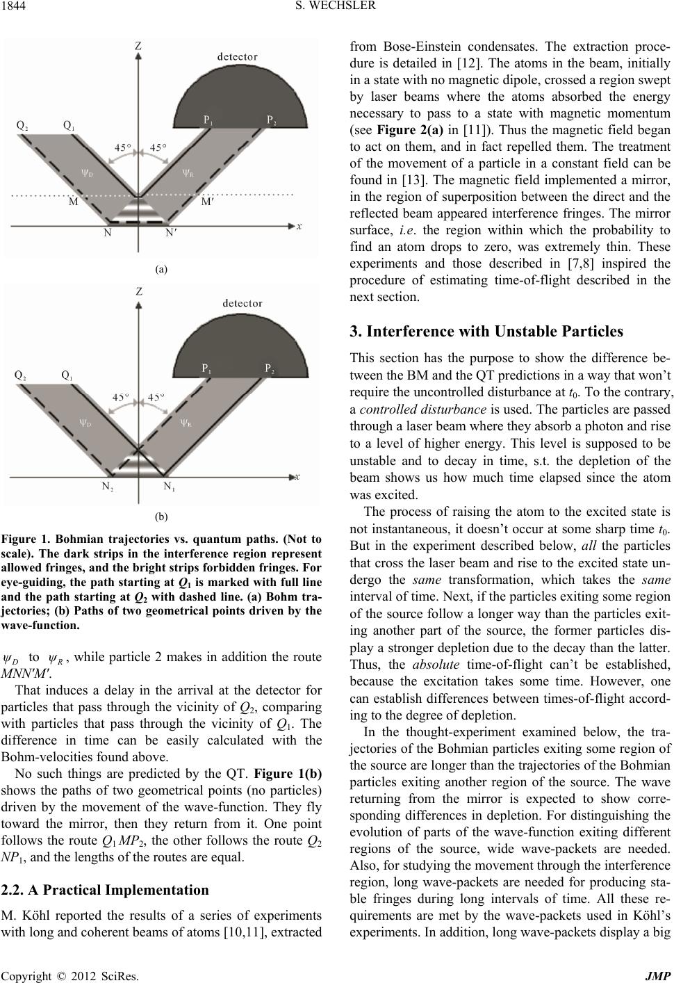 S. WECHSLER 1844 (a) (b) Figure 1. Bohmian trajectories vs. quantum paths. (Not to scale). The dark strips in the interference region represent allowed fringes, and the bright strips forbidde n fringes. For eye-guiding, the path starting at Q1 is marked with full line and the path starting at Q2 with dashed line. (a) Bohm tra- jectories; (b) Paths of two geometrical points driven by the wave-function. ψ to ψ, while particle 2 makes in addition the route MNN'M'. That induces a delay in the arrival at the detector for particles that pass through the vicinity of Q2, comparing with particles that pass through the vicinity of Q1. The difference in time can be easily calculated with the Bohm-velocities found above. No such things are predicted by the QT. Figure 1(b) shows the paths of two geometrical points (no particles) driven by the movement of the wave-function. They fly toward the mirror, then they return from it. One point follows the route Q1 MP2, the other follows the route Q2 NP1, and the lengths of the routes are equal. 2.2. A Practical Implementation M. Köhl reported the results of a series of experiments with long and coherent beams of atoms [10,11], extracted from Bose-Einstein condensates. The extraction proce- dure is detailed in [12]. The atoms in the beam, initially in a state with no magnetic dipole, crossed a region swept by laser beams where the atoms absorbed the energy necessary to pass to a state with magnetic momentum (see Figure 2(a) in [11]). Thus the magnetic field began to act on them, and in fact repelled them. The treatment of the movement of a particle in a constant field can be found in [13]. The magnetic field implemented a mirror, in the region of superposition between the direct and the reflected beam appeared interference fringes. The mirror surface, i.e. the region within which the probability to find an atom drops to zero, was extremely thin. These experiments and those described in [7,8] inspired the procedure of estimating time-of-flight described in the next section. 3. Interference with Unstable Particles This section has the purpose to show the difference be- tween the BM and the QT predictions in a way that won’t require the uncontrolled disturbance at t0. To the contrary, a controlled disturbance is used. The particles are passed through a laser beam where they absorb a photon and rise to a level of higher energy. This level is supposed to be unstable and to decay in time, s.t. the depletion of the beam shows us how much time elapsed since the atom was excited. The process of raising the atom to the excited state is not instantaneous, it doesn’t occur at some sharp time t0. But in the experiment described below, all the particles that cross the laser beam and rise to the excited state un- dergo the same transformation, which takes the same interval of time. Next, if the particles exiting some region of the source follow a longer way than the particles exit- ing another part of the source, the former particles dis- play a stronger depletion due to the decay than the latter. Thus, the absolute time-of-flight can’t be established, because the excitation takes some time. However, one can establish differences between times-of-flight accord- ing to the degree of depletion. In the thought-experiment examined below, the tra- jectories of the Bohmian particles exiting some region of the source are longer than the trajectories of the Bohmian particles exiting another region of the source. The wave returning from the mirror is expected to show corre- sponding differences in depletion. For distinguishing the evolution of parts of the wave-function exiting different regions of the source, wide wave-packets are needed. Also, for studying the movement through the interference region, long wave-packets are needed for producing sta- ble fringes during long intervals of time. All these re- quirements are met by the wave-packets used in Köhl’s experiments. In addition, long wave-packets display a big Copyright © 2012 SciRes. JMP 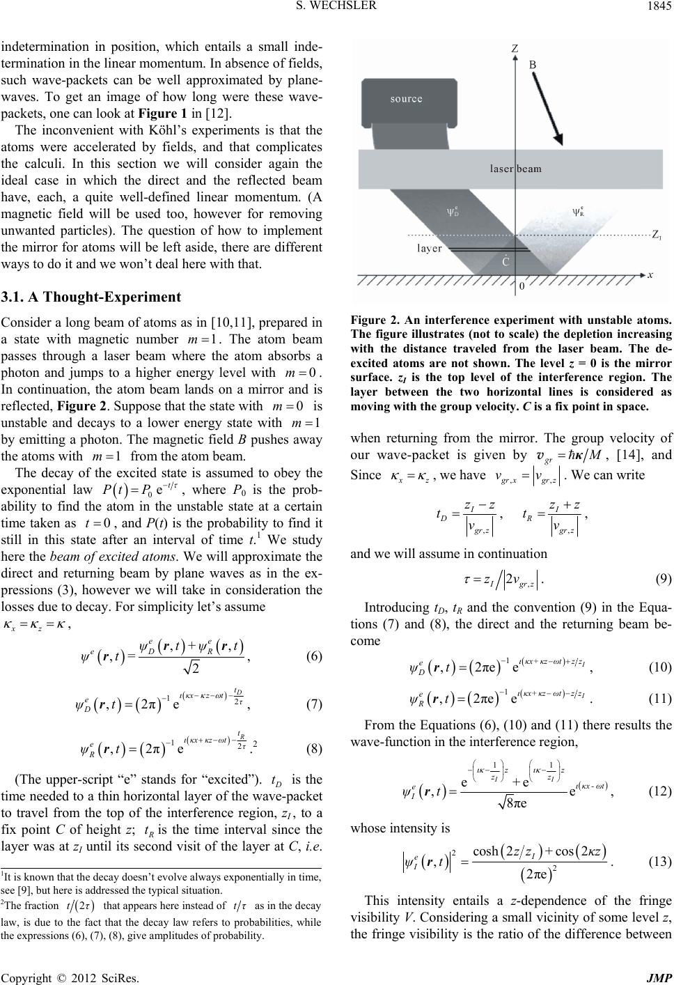 S. WECHSLER 1845 indetermination in position, which entails a small inde- termination in the linear momentum. In absence of fields, such wave-packets can be well approximated by plane- waves. To get an image of how long were these wave- packets, one can look at Figure 1 in [12]. The inconvenient with Köhl’s experiments is that the atoms were accelerated by fields, and that complicates the calculi. In this section we will consider again the ideal case in which the direct and the reflected beam have, each, a quite well-defined linear momentum. (A magnetic field will be used too, however for removing unwanted particles). The question of how to implement the mirror for atoms will be left aside, there are different ways to do it and we won’t deal here with that. 3.1. A Thought-Experiment Consider a long beam of atoms as in [10,11], prepared in a state with magnetic number m. The atom beam passes through a laser beam where the atom absorbs a photon and jumps to a higher energy level with 1 0m . In continuation, the atom beam lands on a mirror and is reflected, Figure 2. Suppose that the state with 0m is unstable and decays to a lower energy state with 1m by emitting a photon. The magnetic field B pushes away the atoms with from the atom beam. 1m The decay of the excited state is assumed to obey the exponential law 0 et PtP , where P0 is the prob- ability to find the atom in the unstable state at a certain time taken as , and P(t) is the probability to find it still in this state after an interval of time t.1 We study here the beam of excited atoms. We will approximate the direct and returning beam by plane waves as in the ex- pressions (3), however we will take in consideration the losses due to decay. For simplicity let’s assume , 0t xz , + , 2 ee DR tψtrr , = eψ ψtr, (6) 2 e 1 , 2π t κx ztτ e D ψt r, (7) 2 e 1 , 2π t κx κzωtτ e R ψt r.2 (8) (The upper-script “e” stands for “excited”). Figure 2. An interference experiment with unstable atoms. The figure illustrates (not to scale) the depletion increasing with the distance traveled from the laser beam. The de- excited atoms are not shown. The level z = 0 is the mirror surface. zI is the top level of the interference region. The layer between the two horizontal lines is considered as moving with the group velocity. C is a fix point in space. when returning from the mirror. The group velocity of our wave-packet is given by t is the time needed to a thin horizontal layer of the wave-packet to travel from the top of the interference region, zI , to a fix point C of height z; tis the time interval since the layer was at zI until its second visit of the layer at C, i.e. κ gr v, [14], and Since z , we have ,, rx grz vv. We can write ,, , II DR rz grz zz zz tt vv , and we will assume in continuation , 2 gr z zv . (9) Introducing tD, tR and the convention (9) in the Equa- tions (7) and (8), the direct and the returning beam be- come 1+ , 2πee κx κzωtzz e D ψt r , (10) 1+ , 2πee κx κzωtzz e R ψt r . (11) From the Equations (6), (10) and (11) there results the wave-function in the interference region, 11 e e , e 8πe II zz zz κx - ωt e I + ψt r , (12) whose intensity is 2 2 cosh2+ cos2 , 2πe I e I zz κz ψtr. (13) 1It is known that the decay doesn’t evolve always exponentially in time, see [9], but here is addressed the typical situation. 2The fraction This intensity entails a z-dependence of the fringe visibility V. Considering a small vicinity of some level z, the fringe visibility is the ratio of the difference between 2tτ that appears here instead of tτ as in the decay law, is due to the fact that the decay law refers to probabilities, while the expressions (6), (7), (8), give amplitudes of probability. Copyright © 2012 SciRes. JMP 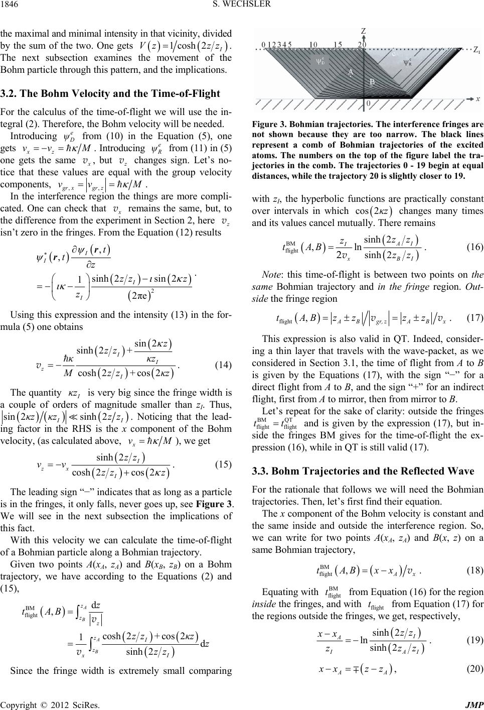 S. WECHSLER 1846 the maximal and minimal intensity in that vicinity, divided by the sum of the two. One gets 1cosh2 Vz zz e . The next subsection examines the movement of the Bohm particle through this pattern, and the implications. 3.2. The Bohm Velocity and the Time-of-Flight For the calculus of the time-of-flight we will use the in- tegral (2). Therefore, the Bohm velocity will be needed. Introducing ψ from (10) in the Equation (5), one gets xz. Introducing vv e M ψ from (11) in (5) one gets the same v, but v changes sign. Let’s no- tice that these values are equal with the group velocity components, ,,gr xgrz In the interference region the things are more compli- cated. One can check that vv M . v remains the same, but, to the difference from the experiment in Section 2, here v isn’t zero in the fringes. From the Equation (12) results 2 sin2 e z , , sinh 2 1 2π I I I I t tz zz z r r . Using this expression and the intensity (13) in the for- mula (5) one obtains sin 2 + + cos2 I z κz zκz sinh 2 cosh 2 I z I zz κ Mz v. (14) The quantity κz is very big since the fringe width is a couple of orders of magnitude smaller than zI. Thus, sinh 2sin 2 I. Noticing that the lead- ing factor in the RHS is the x component of the Bohm velocity, (as calculated above, κzκzzz x vM ), we get sinh cosh 2 zx I vv zz 2 cos 2 I zz z . (15) The leading sign “−” indicates that as long as a particle is in the fringes, it only falls, never goes up, see Figure 3. We will see in the next subsection the implications of this fact. With this velocity we can calculate the time-of-flight of a Bohmian particle along a Bohmian trajectory. Given two points A(xA, zA) and B(xB, z B) on a Bohm trajectory, we have according to the Equations (2) and (15), BM flight d , cosh 2+ 1 sinh 2 A B A B z zz zI z z tAB zz v v cos 2d xI κz z zz Since the fringe width is extremely small comparing Figure 3. Bohmian trajectories. The interference fringes are not shown because they are too narrow. The black lines represent a comb of Bohmian trajectories of the excited atoms. The numbers on the top of the figure label the tra- jectories in the comb. The trajectories 0 - 19 begin at equal distances, while the trajectory 20 is slightly closer to 19. with zI, the hyperbolic functions are practically constant over intervals in which changes many times and its values cancel mutually. There remains cos 2κz BM flight sinh2 , ln sinh 2 AI I xBI zz z tAB zz v2 . (16) Note: this time-of-flight is between two points on the same Bohmian trajectory and in the fringe region. Out- side the fringe region flight , AB AB tABzz zz gr, zx vv BM QT tt . (17) This expression is also valid in QT. Indeed, consider- ing a thin layer that travels with the wave-packet, as we considered in Section 3.1, the time of flight from A to B is given by the Equations (17), with the sign “−” for a direct flight from A to B, and the sign “+” for an indirect flight, first from A to mirror, then from mirror to B. Let’s repeat for the sake of clarity: outside the fringes flightflight and is given by the expression (17), but in- side the fringes BM gives for the time-of-flight the ex- pression (16), while in QT is still valid (17). 3.3. Bohm Trajectories and the Reflected Wave For the rationale that follows we will need the Bohmian trajectories. Then, let’s first find their equation. The x component of the Bohm velocity is constant and the same inside and outside the interference region. So, we can write for two points A(xA, zA) and B(x, z) on a same Bohmian trajectory, BM flight , A tABxx x v BM t t . (18) Equating with flight from Equation (16) for the region inside the fringes, and with flight from Equation (17) for the regions outside the fringes, we get, respectively, sinh2 lnsinh2 I A IAI zz xx zzz . (19) AA xzz , (20) Copyright © 2012 SciRes. JMP 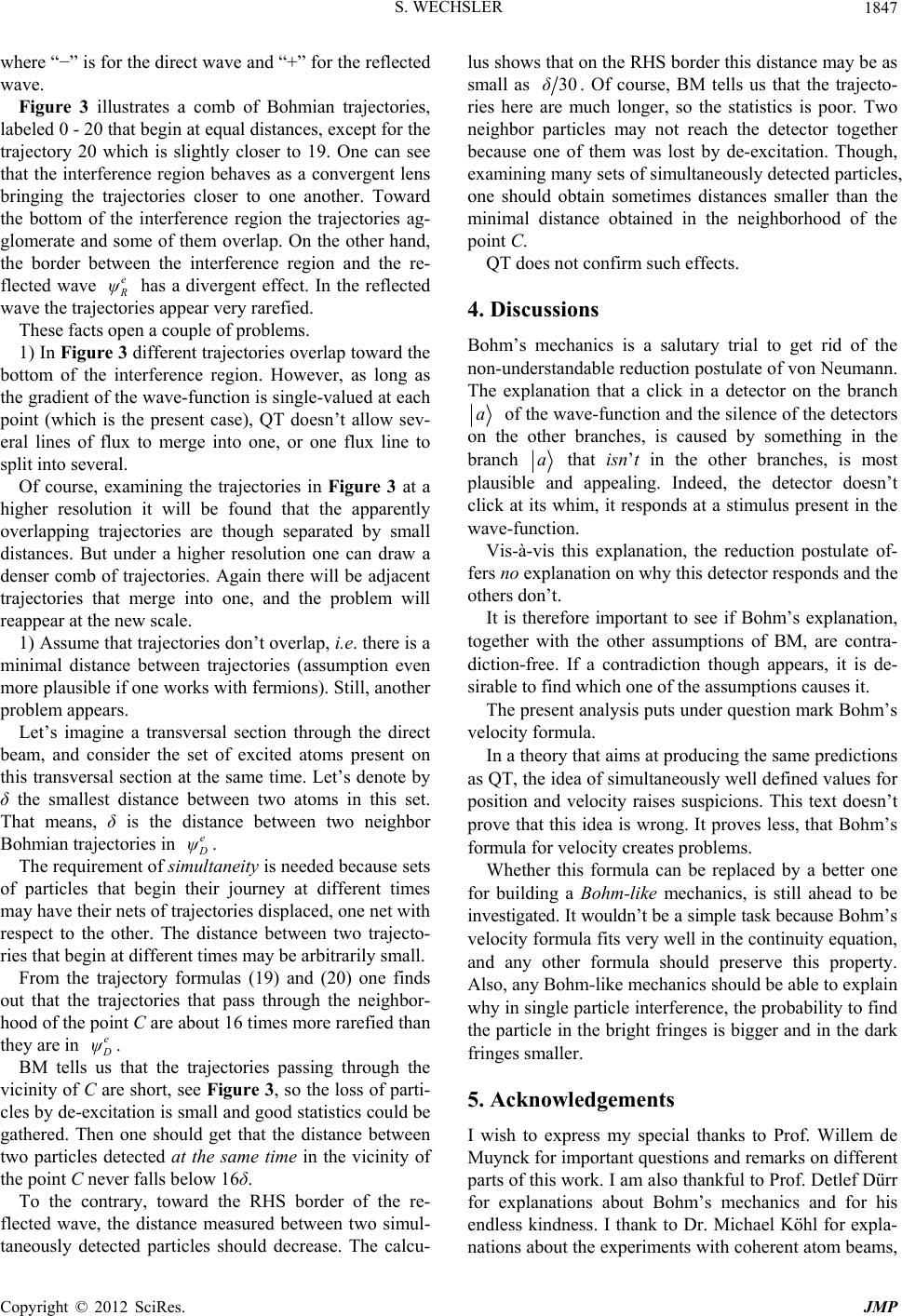 S. WECHSLER 1847 where “−” is for the direct wave and “+” for the reflected wave. Figure 3 illustrates a comb of Bohmian trajectories, labeled 0 - 20 that begin at equal distances, except for the trajectory 20 which is slightly closer to 19. One can see that the interference region behaves as a convergent lens bringing the trajectories closer to one another. Toward the bottom of the interference region the trajectories ag- glomerate and some of them overlap. On the other hand, the border between the interference region and the re- flected wave e ψ e has a divergent effect. In the reflected wave the trajectories appear very rarefied. These facts open a couple of problems. 1) In Figure 3 different trajectories overlap toward the bottom of the interference region. However, as long as the gradient of the wave-function is single-valued at each point (which is the present case), QT doesn’t allow sev- eral lines of flux to merge into one, or one flux line to split into several. Of course, examining the trajectories in Figure 3 at a higher resolution it will be found that the apparently overlapping trajectories are though separated by small distances. But under a higher resolution one can draw a denser comb of trajectories. Again there will be adjacent trajectories that merge into one, and the problem will reappear at the new scale. 1) Assume that trajectories don’t overlap, i.e. there is a minimal distance between trajectories (assumption even more plausible if one works with fermions). Still, another problem appears. Let’s imagine a transversal section through the direct beam, and consider the set of excited atoms present on this transversal section at the same time. Let’s denote by δ the smallest distance between two atoms in this set. That means, δ is the distance between two neighbor Bohmian trajectories in ψ e . The requirement of simultaneity is needed because sets of particles that begin their journey at different times may have their nets of trajectories displaced, one net with respect to the other. The distance between two trajecto- ries that begin at different times may be arbitrarily small. From the trajectory formulas (19) and (20) one finds out that the trajectories that pass through the neighbor- hood of the point C are about 16 times more rarefied than they are in ψ. BM tells us that the trajectories passing through the vicinity of C are short, see Figure 3, so the loss of parti- cles by de-excitation is small and good statistics could be gathered. Then one should get that the distance between two particles detected at the same time in the vicinity of the point C never falls below 16δ. To the contrary, toward the RHS border of the re- flected wave, the distance measured between two simul- taneously detected particles should decrease. The calcu- lus shows that on the RHS border this distance may be as small as 30δ. Of course, BM tells us that the trajecto- ries here are much longer, so the statistics is poor. Two neighbor particles may not reach the detector together because one of them was lost by de-excitation. Though, examining many sets of simultaneously detected particles, one should obtain sometimes distances smaller than the minimal distance obtained in the neighborhood of the point C. QT does not confirm such effects. 4. Discussions Bohm’s mechanics is a salutary trial to get rid of the non-understandable reduction postulate of von Neumann. The explanation that a click in a detector on the branch a of the wave-function and the silence of the detectors on the other branches, is caused by something in the branch a that isn’t in the other branches, is most plausible and appealing. Indeed, the detector doesn’t click at its whim, it responds at a stimulus present in the wave-function. Vis-à-vis this explanation, the reduction postulate of- fers no explanation on why this detector responds and the others don’t. It is therefore important to see if Bohm’s explanation, together with the other assumptions of BM, are contra- diction-free. If a contradiction though appears, it is de- sirable to find which one of the assumptions causes it. The present analysis puts under question mark Bohm’s velocity formula. In a theory that aims at producing the same predictions as QT, the idea of simultaneously well defined values for position and velocity raises suspicions. This text doesn’t prove that this idea is wrong. It proves less, that Bohm’s formula for velocity creates problems. Whether this formula can be replaced by a better one for building a Bohm-like mechanics, is still ahead to be investigated. It wouldn’t be a simple task because Bohm’s velocity formula fits very well in the continuity equation, and any other formula should preserve this property. Also, any Bohm-like mechanics should be able to explain why in single particle interference, the probability to find the particle in the bright fringes is bigger and in the dark fringes smaller. 5. Acknowledgements I wish to express my special thanks to Prof. Willem de Muynck for important questions and remarks on different parts of this work. I am also thankful to Prof. Detlef Dürr for explanations about Bohm’s mechanics and for his endless kindness. I thank to Dr. Michael Köhl for expla- nations about the experiments with coherent atom beams, Copyright © 2012 SciRes. JMP  S. WECHSLER Copyright © 2012 SciRes. JMP 1848 and to Prof. Basil Hiley for relevant information and ma- terial. REFERENCES [1] D. Bohm, “A Suggested Interpretation of the Quantum Theory in Terms of ‘Hidden’ Variables. I,” Physical Re- view, Vol. 85, No. 2, 1952, pp. 166-179. doi:10.1103/PhysRev.85.166 [2] D. Bohm, “A Suggested Interpretation of the Quantum Theory in Terms of ‘Hidden’ Variables. II,” Physical Re- view, Vol. 85, No. 2, 1952, pp. 180-193. doi:10.1103/PhysRev.85.180 [3] D. Dürr, S. Goldstein, R. Tumulka and N. Zanghì, “Boh- mian Mechanics,” quant-ph/0903.2601, p. 3. [4] D. Dürr and S. Teufel, “Bohmian Mechanics the Physics and Mathematics of Quantum Theory,” Springer, 2008. [5] J. G. Muga, R. Sala and J. P. Palao, “The Time of Arrival Concept in Quantum Mechanics,” quant-ph/9801043v1. [6] C. Anastopoulos and N. Savvidou, “Time-of-Arrival Prob- abilities for General Particle Detectors,” quant-ph/1205.27 81v3. [7] J. G. Muga, A. D. Baute, J. A. Damborenea and I. L. Egusquiza, “Model for the Arrival-Time Distribution in Fluorescence Time-of-Flight Experiments,” quant-ph/00 09111v1. [8] J. A. Damborenea, I. L. Egusquiza, G. C. Hegerfeldt and J. G. Muga, “Atomic Time-of-Arrival Measurements with a Laser of Finite Beam Width,” quant-ph/0302201v1. [9] C. Anastopoulos, “Time-of-Arrival Probabilities and Quan- tum Measurements: III Decay of Unstable States,” quant- ph/0706.2496v2. [10] M. Köhl, T. W. Hänsch and T. Esslinger, “Measuring the Temporal Coherence of an Atom Laser Beam,” cond- mat/0104384v2. [11] I. Bloch, M. Köhl, M. Greiner, T. W. Hänsch and T. Esslinger, “Optics with an Atom Laser Beam,” Physical Review Letters, Vol. 87, No. 3, 2001, Article ID: 030401. doi:10.1103/PhysRevLett.87.030401 [12] I. Bloch, T. W. Hänsch and T. Esslinger, “Atom Laser with a cw Output Coupler,” cond-mat/9812.258v1. [13] L. D. Landau and E. M. Lifshitz, “Quantum Mechanics,” Pergamon Press, Oxford, 1958, p. 24. [14] G. Baym, “Lectures on Quantum Mechanics,” 3rd Edition, W. A. Benjamin, Inc., Massachusetts, 1974, p. 64.
|