Paper Menu >>
Journal Menu >>
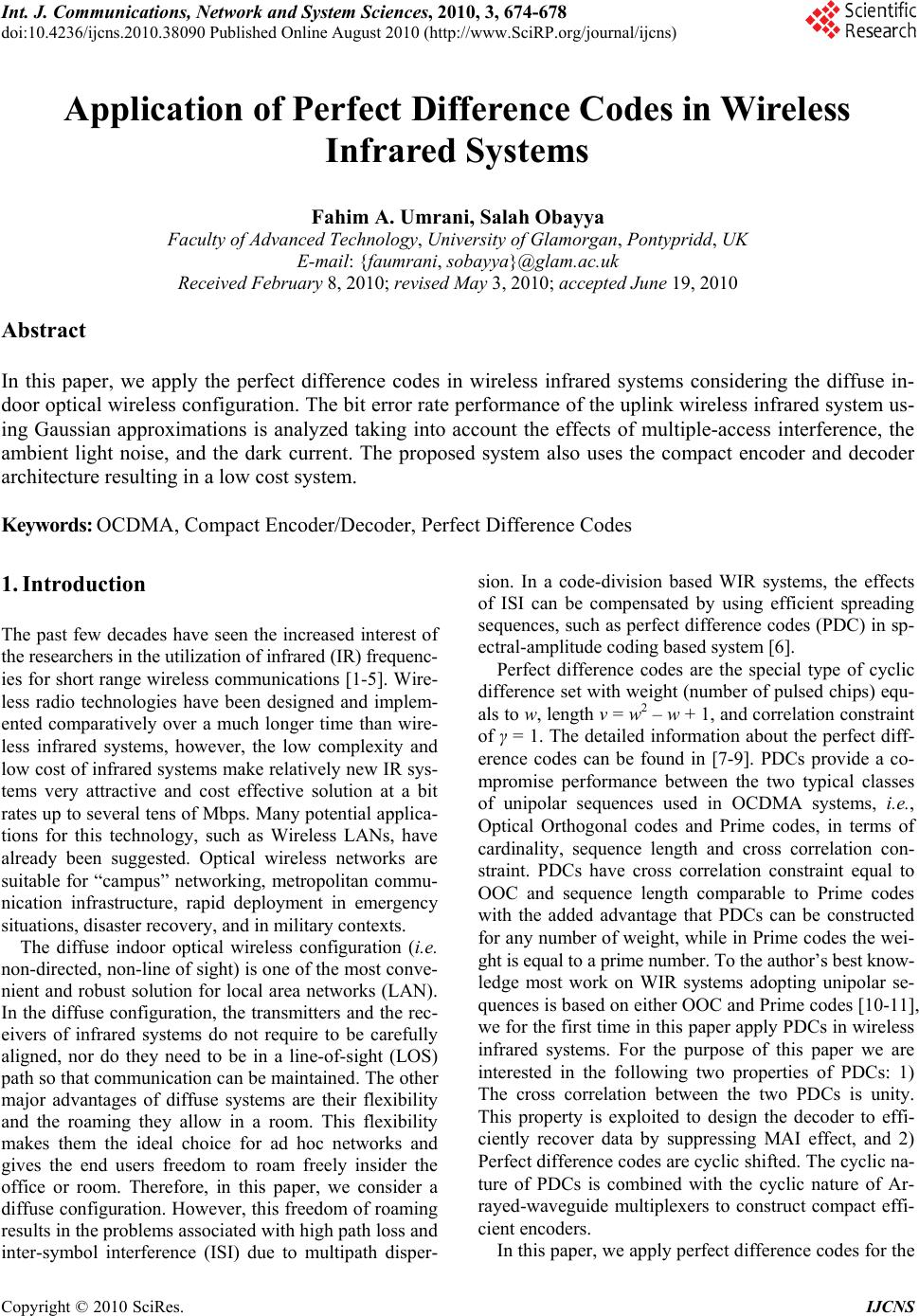 Int. J. Communications, Network and System Sciences, 2010, 3, 674-678 doi:10.4236/ijcns.2010.38090 Published Online August 2010 (http://www.SciRP.org/journal/ijcns) Copyright © 2010 SciRes. IJCNS Application of Perfect Difference Codes in Wireless Infrared Systems Fahim A. Umrani, Salah Obayya Faculty of Advanced Technology, University of Glamorgan, Pontypridd, UK E-mail: {faumrani, sobayya}@glam.ac.uk Received February 8, 2010; revised May 3, 2010; accepted June 19, 2010 Abstract In this paper, we apply the perfect difference codes in wireless infrared systems considering the diffuse in- door optical wireless configuration. The bit error rate performance of the uplink wireless infrared system us- ing Gaussian approximations is analyzed taking into account the effects of multiple-access interference, the ambient light noise, and the dark current. The proposed system also uses the compact encoder and decoder architecture resulting in a low cost system. Keywords: OCDMA, Compact Encoder/Decoder, Perfect Difference Codes 1. Introduction The past few decades have seen the increased interest of the researchers in the utilization of infrared (IR) frequenc- ies for short range wireless communications [1-5]. Wire- less radio technologies have been designed and implem- ented comparatively over a much longer time than wire- less infrared systems, however, the low complexity and low cost of infrared systems make relatively new IR sys- tems very attractive and cost effective solution at a bit rates up to several tens of Mbps. Many potential applica- tions for this technology, such as Wireless LANs, have already been suggested. Optical wireless networks are suitable for “campus” networking, metropolitan commu- nication infrastructure, rapid deployment in emergency situations, disaster recovery, and in military contexts. The diffuse indoor optical wireless configuration (i.e. non-directed, non-line of sight) is one of the most conve- nient and robust solution for local area networks (LAN). In the diffuse configuration, the transmitters and the rec- eivers of infrared systems do not require to be carefully aligned, nor do they need to be in a line-of-sight (LOS) path so that communication can be maintained. The other major advantages of diffuse systems are their flexibility and the roaming they allow in a room. This flexibility makes them the ideal choice for ad hoc networks and gives the end users freedom to roam freely insider the office or room. Therefore, in this paper, we consider a diffuse configuration. However, this freedom of roaming results in the problems associated with high path loss and inter-symbol interference (ISI) due to multipath disper- sion. In a code-division based WIR systems, the effects of ISI can be compensated by using efficient spreading sequences, such as perfect difference codes (PDC) in sp- ectral-amplitude coding based system [6]. Perfect difference codes are the special type of cyclic difference set with weight (number of pulsed chips) equ- als to w, length v = w2 – w + 1, and correlation constraint of γ = 1. The detailed information about the perfect diff- erence codes can be found in [7-9]. PDCs provide a co- mpromise performance between the two typical classes of unipolar sequences used in OCDMA systems, i.e., Optical Orthogonal codes and Prime codes, in terms of cardinality, sequence length and cross correlation con- straint. PDCs have cross correlation constraint equal to OOC and sequence length comparable to Prime codes with the added advantage that PDCs can be constructed for any number of weight, while in Prime codes the wei- ght is equal to a prime number. To the author’s best know- ledge most work on WIR systems adopting unipolar se- quences is based on either OOC and Prime codes [10-11], we for the first time in this paper apply PDCs in wireless infrared systems. For the purpose of this paper we are interested in the following two properties of PDCs: 1) The cross correlation between the two PDCs is unity. This property is exploited to design the decoder to effi- ciently recover data by suppressing MAI effect, and 2) Perfect difference codes are cyclic shifted. The cyclic na- ture of PDCs is combined with the cyclic nature of Ar- rayed-waveguide multiplexers to construct compact effi- cient encoders. In this paper, we apply perfect difference codes for the 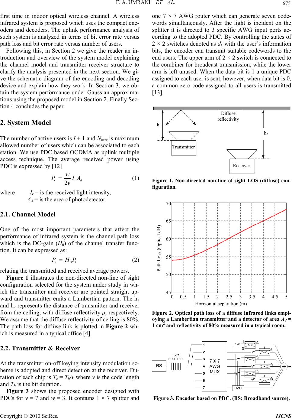 F. A. UMRANI ET AL. 675 first time in indoor optical wireless channel. A wireless infrared system is proposed which uses the compact enc- oders and decoders. The uplink performance analysis of such system is analyzed in terms of bit error rate versus path loss and bit error rate versus number of users. Following this, in Section 2 we give the reader an in- troduction and overview of the system model explaining the channel model and transmitter receiver structure to clarify the analysis presented in the next section. We gi- ve the schematic diagram of the encoding and decoding device and explain how they work. In Section 3, we ob- tain the system performance under Gaussian approxima- tions using the proposed model in Section 2. Finally Sec- tion 4 concludes the paper. 2. System Model The number of active users is I + 1 and Nmax is maximum allowed number of users which can be associated to each station. We use PDC based OCDMA as uplink multiple access technique. The average received power using PDC is expressed by [12] drr AI v w P2 (1) where Ir = is the received light intensity, Ad = is the area of photodetector. 2.1. Channel Model One of the most important parameters that affect the performance of infrared system is the channel path loss which is the DC-gain (H0) of the channel transfer func- tion. It can be expressed as: tr PHP 0 (2) relating the transmitted and received average powers. Figure 1 illustrates the non-directed non-line of sight configuration selected for the system under study in wh- ich the transmitter and receiver are pointed straight up- ward and transmitter emits a Lambertian pattern. The h1 and h2 represents the distance of transmitter and receiver from the ceiling, with diffuse reflectivity ρ, respectively. We assume that the diffuse reflectivity of ceiling is 80%. The path loss for diffuse link is plotted in Figure 2 wh- ich is measured in a typical office [4]. 2.2. Transmitter & Receiver At the transmitter on-off keying intensity modulation sc- heme is adopted and direct detection at the receiver. Du- ration of each chip is Tc = Tb/v where v is the code length and Tb is the bit duration. Figure 3 shows the proposed encoder designed with PDCs for v = 7 and w = 3. It contains 1 × 7 splitter and one 7 × 7 AWG router which can generate seven code- words simultaneously. After the light is incident on the splitter it is directed to 3 specific AWG input ports ac- cording to the adopted PDC. By controlling the states of 2 × 2 switches denoted as dk with the user’s information bits, the encoder can transmit suitable codewords to the end users. The upper arm of 2 × 2 switch is connected to the combiner for broadcast transmission, while the lower arm is left unused. When the data bit is 1 a unique PDC assigned to each user is sent, however, when data bit is 0, a common zero code assigned to all users is transmitted [13]. h1 Diffuse reflectivity Receiver Transmitte r h2 Figure 1. Non-directed non-line of sight LOS (diffuse) con- figuration. Horizontal se p aration ( m ) 0 0.5 1 1.5 2 2.5 3 3.5 4 4.5 5 Path Loss (Optical dB) 70 65 60 55 50 45 Figure 2. Optical path loss of a diffuse infrared links empl- oying a Lambertian transmitter and a detector of area Ad = 1 cm2 and reflectivity of 80% measured in a typical room. Figure 3. Encoder based on PDC. (BS: Broadband source). Copyright © 2010 SciRes. IJCNS 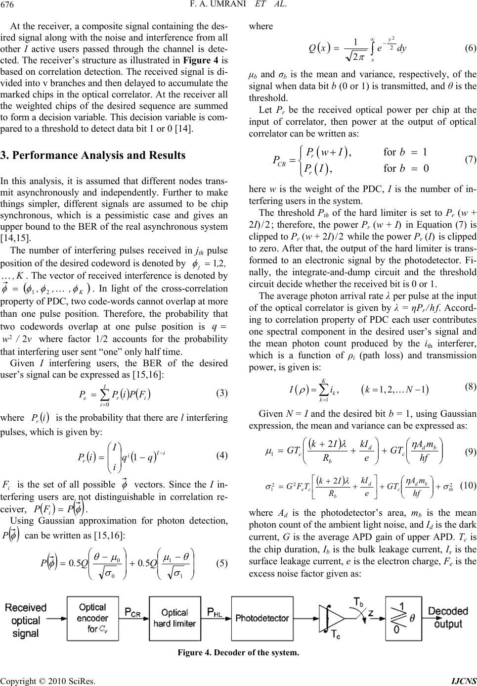 F. A. UMRANI ET AL. Copyright © 2010 SciRes. IJCNS 676 At the receiver, a composite signal containing the des- ired signal along with the noise and interference from all other I active users passed through the channel is dete- cted. The receiver’s structure as illustrated in Figure 4 is based on correlation detection. The received signal is di- vided into v branches and then delayed to accumulate the marked chips in the optical correlator. At the receiver all the weighted chips of the desired sequence are summed to form a decision variable. This decision variable is com- pared to a threshold to detect data bit 1 or 0 [14]. where x y dyexQ 2 2 2 1 (6) μb and σb is the mean and variance, respectively, of the signal when data bit b (0 or 1) is transmitted, and θ is the threshold. Let Pr be the received optical power per chip at the input of correlator, then power at the output of optical correlator can be written as: , for 1 , for 0 r CR r Pw Ib PPI b (7) 3. Performance Analysis and Results In this analysis, it is assumed that different nodes trans- mit asynchronously and independently. Further to make things simpler, different signals are assumed to be chip synchronous, which is a pessimistic case and gives an upper bound to the BER of the real asynchronous system [14,15]. here w is the weight of the PDC, I is the number of in- terfering users in the system. The threshold Pth of the hard limiter is set to Pr (w + 2I)/2; therefore, the power Pr (w + I) in Equation (7) is clipped to Pr (w + 2I)/2 while the power Pr (I) is clipped to zero. After that, the output of the hard limiter is trans- formed to an electronic signal by the photodetector. Fi- nally, the integrate-and-dump circuit and the threshold circuit decide whether the received bit is 0 or 1. The number of interfering pulses received in jth pulse position of the desired codeword is denoted by ,, j21 . The vector of received interference is denoted by K, K ,,, 21 . In light of the cross-correlation property of PDC, two code-words cannot overlap at more than one pulse position. Therefore, the probability that two codewords overlap at one pulse position is q where factor 1/2 accounts for the probability that interfering user sent “one” only half time. v/w 2 2 The average photon arrival rate λ per pulse at the input of the optical correlator is given by λ = ηPr/hf. Accord- ing to correlation property of PDC each user contributes one spectral component in the desired user’s signal and the mean photon count produced by the ith interferer, which is a function of ρi (path loss) and transmission power, is given is: Given I interfering users, the BER of the desired user’s signal can be expressed as [15,16]: 1 , 1,2,1 K k k IikN (8) I i ireFPiPP 0 (3) Given N = I and the desired bit b = 1, using Gaussian expression, the mean and variance can be expressed as: where is the probability that there are l interfering pulses, which is given by: iP r hf mA GT e kI R Ik GT bd c d b c 2 1 (9) iI i rqq i I iP 1 (4) 2 2 2 1 2 th bd c d b ce hf mA GT e kI R Ik TFG (10) i is the set of all possible F vectors. Since the I in- terfering users are not distinguishable in correlation re- ceiver, PFP i. where Ad is the photodetector’s area, mb is the mean photon count of the ambient light noise, and Id is the dark current, G is the average APD gain of upper APD. Tc is the chip duration, Ib is the bulk leakage current, Is is the surface leakage current, e is the electron charge, Fe is the excess noise factor given as: Using Gaussian approximation for photon detection, P can be written as [15,16]: 1 1 0 05050 Q.Q.P (5) Figure 4. Decoder of the system.  F. A. UMRANI ET AL. Copyright © 2010 SciRes. IJCNS 677 effeffe kG/GkF 112 (11) here keff is the APD effective ionization ratio and, 2 th is the variance of thermal noise given as: L cnb th Re TTK 2 22 (12) where Kb is the Boltzman’s constant, Tn is the receiver noise temperature, and RL is the receiver load resistance. Given N = I and the desired bit b = 0, using Gaussian expression, the mean and variance can be expressed as: hf mA GT e kI GT bd c d c 0 (13) 22 0th bd c d chf mA GT e kI GT (14) To minimize the BER, the optimal threshold θ can be derived as: 2 0 2 1 2 0 2 1 for , a acbb for ,/ 2 01 2 (15) where 2 0 2 1 a (16) 10 2 0 2 1 b (17) 2 0 2 1 2 1 2 0 2 1 2 0 2 0 2 1 lnc (18) Now, we present some numerical results for the wire- less infrared system discussed above. We assume an infrared CDMA system with data rate of Rb = 2 Mbps per user and PDC codewords with length v = 183 and weight w = 14. The system is operating at the wave- length of λ = 850 nm, the ambient light noise intensity is mb = 490 μW/cm2 the quantum efficiency of the Photodetector is η = 0.6, Photodetector’s area is Ad = 1 cm2 and dark current is assumed to be Id = 160 nA. The other parameters are listed in Table 1. Figure 5 illustrates the bit error rate performance of the indoor optical distance versus the user’s distance (ρ) from the base station for transmission powers of 5 mW, 20 mW, 15 mW and 30 mW. The number of interfering users is kept fixed. One can see the near-far problem in a basic PDC wireless infrared network without power con- trol. As the distance from the base station is increased the system performance degrades rapidly. This shows that the users which are near the base station obtain much more BER than needed but the data from far users can not be detected with desired BER. This generates the re- quirement of a power control algorithm in indoor wire- less system to make sure that all users regardless of their distance from the base station can access the base station with equal power. Figure 6 plots the error probability versus user’s dis- tance from the base station for different bit rates (2, 4 and 10 Mbps). The transmitted power and the number of interferes is kept fixed at Pt = 20 mW and 5, respectively. Table 1. Parameters used. PD quantum efficiency η = 0.6 Gain of the APD 100 Receiver noise temperature Tn = 300 K Receiver load resistor RL = 1030 Ω User’s difference from base station, ρ (m) BE R 10 0 10 -5 10 -10 10 -15 10 -20 10 -25 10 -30 0 0.5 1 1.5 2 2.5 3 3.5 4 P t = 5 mW P t = 10 mW P t = 15 mW P t = 30 mW Figure 5. BER versus for various transmission powers. Nu- mber of interferes is 5. User’s difference from base station, ρ (m) BE R 10 0 10 -5 10 -10 10 -15 10 -20 10 -25 10 -30 0 0.5 1 1.5 2 2.5 3 3.5 4 10 Mbps 4 Mbps 2 Mbps Figure 6. BER versus user’s distance from base station (ρ) for various bit rates. Number of interferes is 5 and Pt = 20 mW.  678 F. A. UMRANI ET AL. N umber of simultaneous users BE R 10 0 10 -5 10 -10 10 -15 10 -20 10 -25 10 -30 5 10 15 20 25 30 20 mW 10 mW 5 mW Figure 7. Error probability versus number of users for data rate of 2 Mbps. It can be seen that the path loss as the user’s move away from the base station puts severe restrictions on the data rate. In Figure 7, the bit error rate versus number of us- ers is plotted. We can see that as the number of users increase the bit error rate performance is improved. The reason for this again can be found in Equation (7) which shows the increase in the number of users is directly proportional to the difference between data bit 1 and 0. 4. Summary In this paper, we applied perfect difference codes in wire- less domain. The uplink performance in presence of var- ious noise sources such as path loss, ambient noise, mul- tiple access interference and thermal noise is analyzed. The bit error rate performance was analyzed over differ- ent transmission powers and different data rates. It is revealed from the results that an effective power control algorithm is required to mitigate path loss effects. 5. Acknowledgements This research is supported by Mehran University of En- gineering & Technology, Pakistan. 6. References [1] F. R. Gfeller, and U. Bapst, “Wireless in-House Data Com- munication via Diffuse Infrared Radiation,” Proceedings of the IEEE, Vol. 67, No. 11, 1979, pp. 1474-1486. [2] J. R. Barry, J. M. Kahn, et al., “Simulation of Multipath Impulse Response for Indoor Wireless Optical Channels,” IEEE Journal on Selected Areas in Communications, Vol. 11, No. 3, 1993, pp. 367-379. [3] J. B. Carruthers and J. M. Kahn, “Modelling of Nondi- rected Wireless Infrared Channels,” IEEE Transactions on Communications, Vol. 45, No. 10, 1997, pp. 1260-1268. [4] J. M. Kahn, P. Djahani, A. G. Weisbin, K. T. Beh, A. P. Tang and R. You, “Imaging Diversity Receivers for High-Speed Infrared Wireless Communications,” IEEE Communications Magazine, Vol. 36, No. 12, 1998, pp. 88-94. [5] Z. Ghassemlooy and A. C. Boucouvalas, “Guest Editorial: Indoor Optical Wireless Communications System and Net- works,” International Journal of Communication Systems, Vol. 18, No. 3, 2005, pp. 191-193. [6] F. A. Umrani and S. Obayya, “New Encoder/Decoder Design for Spectral Amplitude Coding Based Optical Code Division Multiplexing (OCDM) System with Com- mon Zero Code,” submitted for publication. [7] X.-S. Weng and J. S. Wu, “Perfect Difference Codes for Synchronous Fiber-Optic CDMA Communication Sys- tems,” Journal of Lightwave Technology, Vol. 19, No. 2, 2001, pp. 186-194. [8] M. Hall, Jr., “Combinatorial Theory,” Blaisdell Publish- ing Company, London, 1967. [9] H. J. Ryser, “Combinatorial Mathematics,” Wiley, New York, 1963. [10] T. Satoh and T. Hashimoto, “Performance Evaluation of Chip-Synchronous, Code-Asynchronous Optical CDMA Systems for Indoor Infrared Wireless Communications with Diffuse Link,” Electronics and Communications in Japan, Vol. 86, No. 4, 2002, pp. 75-88. [11] B. M. Ghaffari, M. D. Matinfar and J. A. Salehi, “Wire- less Optical CDMA LAN: Digital Implementation Ana- lysis,” IEEE Journal on Selected Areas in Communica- tions, Vol. 27, No. 9, 2009, pp. 1676-1686. [12] S. Zahedi, J. A. Salehi and M. Nasiri-Kenari, “A Photon Counting Approach to the Performance Analysis of In- doors Wireless Infrared CDMA Networks,” Proceedings of IEEE Personal, Indoor and Mobile Radio Communica- tions, London, Vol. 2, 18-21 September 2000, pp. 928- 932. [13] L.-L. Jau and Y.-H. Lee, “Optical Code-Division Multi- plexing Systems Using Common-Zero Codes,” Micro- wave and Optical Technology Letters, Vol. 39, No. 2, 2003, pp. 165-167. [14] J. A. Salehi and C. A. Brackett, “Code Division Multiple Access Techniques in Optical Fiber Networks–Part II: Systems Performance Analysis,” IEEE Transactions on Communications, Vol. 37, No. 8, 1989, pp. 834-842. [15] A. Aminzadeh-Gohari and M. R. Pakravan, “Analysis of Power Control for Indoor Wireless Infrared CDMA Com- munication,” Proceedings of 25th IEEE International Per- formance, Computing, and Communications Conference, Phoenix, Vol. 6, 10-12 April 2006, pp. 297-302. [16] M. Azizoglu, J. A. Salehi and Y. Li, “Optical CDMA via Temporal Codes,” IEEE Transactions on Communica- tions, Vol. 40, No. 7, 1992, pp. 1162-1170. Copyright © 2010 SciRes. IJCNS |