Open Journal of Fluid Dynamics
Vol.2 No.4A(2012), Article ID:26367,5 pages DOI:10.4236/ojfd.2012.24A043
A Twin Unidirectional Impulse Turbine for Wave Energy Conversion
—Effect of Guide Vane Solidity on the Performance
1Techno Center, Matsue College of Technology, Matsue, Japan
2Department of Mechanical Engineering, Matsue College of Technology, Matsue, Japan
3Institute of Ocean Energy, Saga University, Saga, Japan
Email: takao@matsue-ct.jp
Received September 29, 2012; revised November 11, 2012; accepted November 20, 2012
Keywords: Fluid Machinery; Impulse Turbine; Wave Energy Conversion; Ocean Energy
ABSTRACT
A twin unidirectional impulse turbine has been proposed in order to enhance the performance of wave energy plant. This turbine system uses two unidirectional impulse turbines and their flow direction is different each other. However, the effect of guide vane solidity on the turbine characteristics has not been clarified to date. The performances of a unidirectional impulse turbine under steady flow conditions were investigated experimentally by using a wind tunnel with large piston/cylinder in this study. Then, mean efficiency of the twin impulse turbine in bidirectional airflow has been estimated by a quasi-steady analysis using experimental results in order to investigate the effect of guide vane solidity on the performance.
1. Introduction
In recent years, the power take-off mechanism in the oscillating water column (OWC) based wave energy plant has generally comprised of a bidirectional turbine, such as Wells turbine [1]. However, in general, bidirectional turbines have inherent disadvantages: relatively low efficiency and poor starting characteristics because bidirectional turbines have symmetrical configuration with respect to the plane perpendicular to the rotor axis in order to operate in bidirectional reciprocating flow.
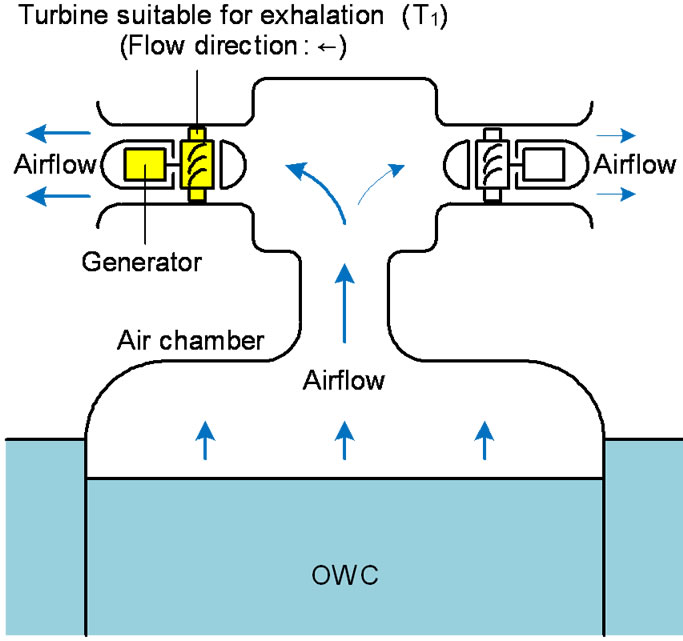
An alternative to the use of a bidirectional turbine is an approach utilizing a unidirectional turbine with two or four valves that act to force air into the turbine in the same direction during exhalation or inhalation from air chamber. Although it has had success in navigational buoys for 30 years, the principle was not adopted in larger plant. However, a unidirectional turbine that showed good efficiency over a broad range [2]. A new topology with twin impulse turbine has been proposed and a laboratory model of the concept was built at IIT Madras, India [3]. The basic arrangement of the twin unidirectional topology is shown in Figure 1. The power take-off mechanism utilizes two unidirectional impulse turbines, T1 and T2 coupled to electrical generators. It was conjectured that during intake, the air would flow into the OWC via the turbine T1 and during exhaust the air would flow out from the OWC through T2. The use of twin unidirectional turbines ensures that, even without the use of valves, each turbine in effect works for half a cycle.
The objective of this paper is to investigate the effect of guide vane solidity on the performance of twin unidirectional impulse turbine for wave energy conversion, in order to clarify the suitable geometry of the turbine. The performance is estimated by a quasi-steady analysis using experimental results in the study.
2. Experimental Setup and Procedure
The experimental setup and procedure are the same to Refs. [2,4]. A schematic view of the test rig is shown in Figure 2. The test rig consists of a large piston-cylinder (diameter: 1.4 m, length: 1.7 m), a settling chamber and a 300-mm-diameter test section with the inlet and outlet bell-mouth. The turbine rotor was placed at the center of the test section and tested at a constant rotational speed under steady and sinusoidal flow conditions. In the steady flow condition, the flow rate through the turbine was measured by Pitot tube. The overall performance of unidirectional impulse turbine was evaluated by torque To, flow rate Q, rotor angular velocity ω, and total pressure drop through the turbine ∆p. The tests were performed for the total pressure drops up to 4.0 kPa, the flow rates up to 0.320 m3/s, and the angular velocities up
 (a)
(a)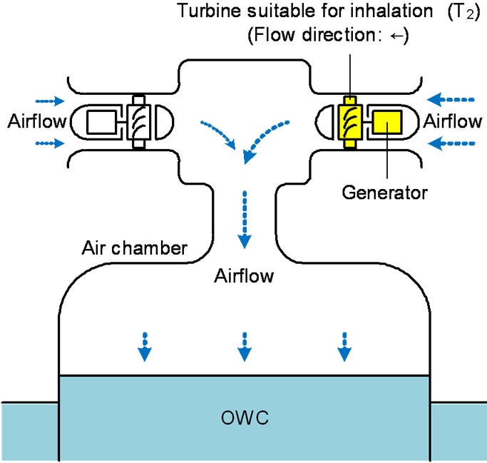 (b)
(b)
Figure 1. Principle of twin impulse turbine. (a) Exhalation; (b) Inhalation.
to 370 rad/s. The Reynolds number based on rotor blade chord was approximately equal to 8 × 10⁴ at the peak efficiency.
Concerning the tested rotor, the chord length of rotor blade: 54 mm; height: 44 mm; tip diameter: 298 mm; tip clearance: 1 mm; solidity at mean radius: 2.0; radius of leading edge: 1.5 mm; radius of trailing edge: 0.5 mm; hub-to-tip ratio h: 0.7. The blade profile is shown in Figure 3.
The guide vane profile used in the experiments is study consists of a straight line and a circular arc as shown in Figure 4. The specifications of guide vane are as follows: the chord length l: 70 mm; thickness: 0.5 mm; setting angle: 20˚. The guide vane solidity at mean radius 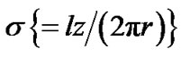 is ranging from 1.1 to 2.8, in order to clarify the effect of its solidity on the performance.
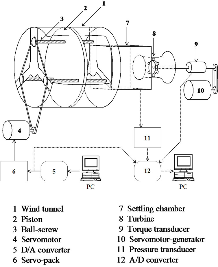
Figure 2. Test apparatus and measuring system.
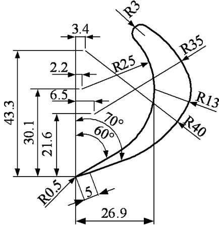
Figure 3. Rotor blade profile.
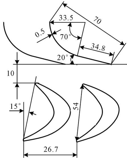
Figure 4. Turbine configuration.
3. Experimental Results
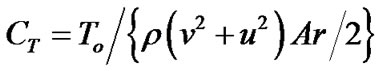
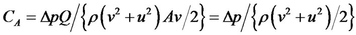
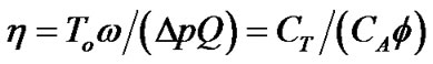
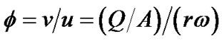
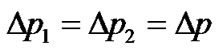
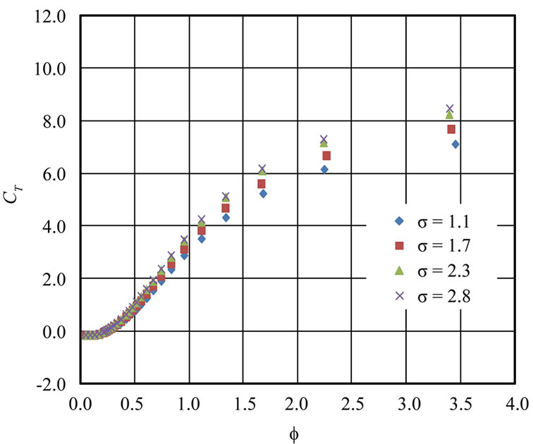
The turbine performance under steady flow conditions is evaluated by torque coefficient CT, input coefficient CA and turbine efficiency η against flow coefficient . The definitions of these parameters are as follows:
 (1)
(1)
 (2)
(2)
 (3)
(3)
 (4)
(4)
where A, r, u, v and ρ denote flow passage area , mean radius
 , circumferential velocity at mean radius, axial flow velocity and density of air, respectively.
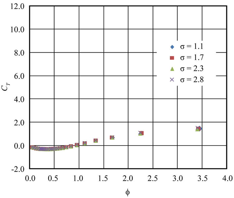
Figures 5 and 6 show the experimental results and the effect of guide vane solidity on the turbine characteristics. As is evident from the figures, torque coefficient CT, input coefficient CA and efficiency η increase with σ in the case of forward flow. The peak efficiency in the case of forward flow is 0.72 at σ = 2.3 and 2.8. But CT and η in the case of reverse flow are quite low when compared to the case of forward flow, especially the peak efficiency is approximately 0.03 only. Therefore, the turbine under reverse flow condition cannot convert from the pneumatic energy in the air chamber to the mechanical energy of rotation. CA in the case of reverse flow is quite higher than the case of forward flow. The difference of CA between forward flow and reverse flow affects the flow rate of reverse flow in the twin turbine.
4. Estimation Method of Turbine Characteristics under Sinusoidal Airflow Conditions
Since the airflow into the turbine is generated by the OWC, it is very important to demonstrate the turbine characteristics under oscillating flow conditions. Here let us simulate the characteristics under sinusoidal flow conditions (Figure 7) in order to clarify the effect of number of generators on the turbine characteristics. The steady flow characteristics of the turbine in Figures 5(a) and (b), 6(a) and (b) are assumed to be valid for computing performance under unsteady flow conditions. Such a quasisteady analysis has been validated by previous studies [4,5].
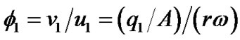
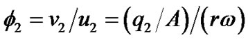
In the calculation, flow rates through the two turbines are obtained by using the steady flow characteristics and solving these simultaneous equations.
 (5)
(5)
 (6)
(6)
 (a)
(a)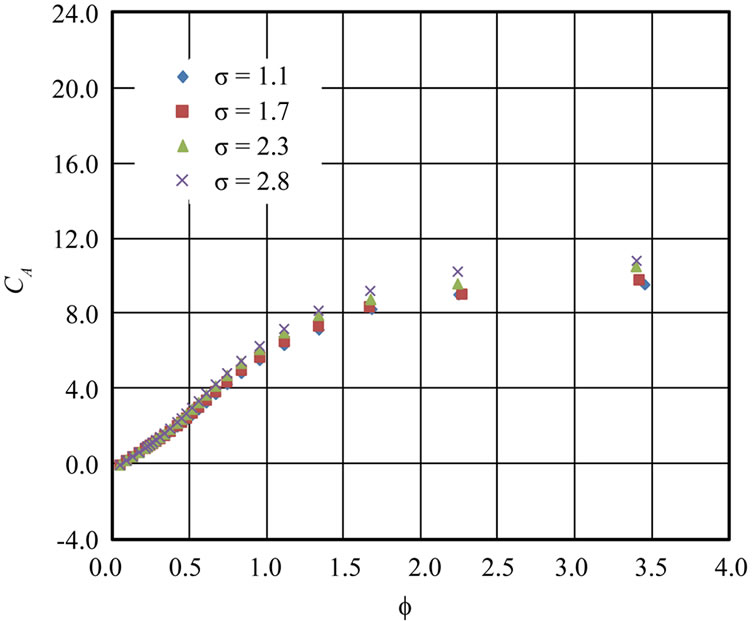 (b)
(b) (c)
(c)
Figure 5. Effect of guide vane solidity on turbine characteristics in forward flow. (a) Torque coefficient; (b) Input coefficient; (c) Efficiency.
 (a)
(a)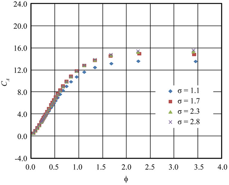 (b)
(b)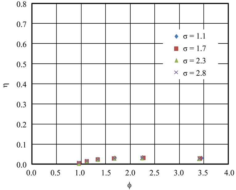 (c)
(c)
Figure 6. Effect of guide vane solidity on turbine characteristics in reverse flow. (a) Torque coefficient; (b) Input coefficient; (c) Efficiency.
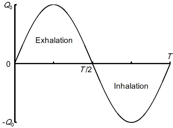
Figure 7. Sinusoidal airflow.
 (7)
(7)
 (8)
(8)
where q denote flow rate through the turbine and subscripts 1 and 2 mean turbines T1 and T2, respectively (see Figure 1). Further, flow rate and rotor angular velocity in the calculations are assumed as follows:
 (9)
(9)
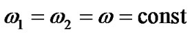 . (10)
where Q0, t and T are maximum flow rate, time and period of sinusoidal airflow, respectively.
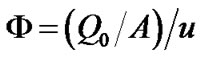
When the turbine is in the running conditions, the parameters such as To, w, Dp and q vary periodically in a sinusoidal oscillating flow. In this case, the turbine performances should be represented by mean value such as mean efficiency. Assuming that only the turbine under forward flow condition operates, in the case of two generators, the running characteristics of the twin turbine under sinusoidal flow condition are evaluated by mean efficiency ηm against the flow coefficient F, which are defined as follows:
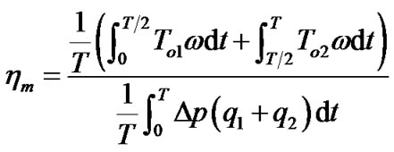 (11)
(11)
 (12)
(12)
Figure 8 shows the simulation results. It is found from the figure that the mean efficiency of the twin turbine ηm increases with the solidity σ and its maximum value is 0.45 at σ = 2.8. However, the peak efficiencies in the cases of 1.7 ≤ σ ≤ 2.8 are almost the same. Therefore, it seems that the suitable solidity for guide vane is approximately 2. On the other hand, the peak value of ηm decreases by 0.22 when compared with the maximum efficiency under steady flow condition in Figure 5(c). Because a part of airflow passes through the turbine under reverse flow condition and the wave energy plant
Figure 8. Effect of guide vane solidity on mean efficiency under sinusoidal flow conditions.
loses pneumatic energy which is converted from ocean wave [5].
5. Conclusions
The performance of twin unidirectional impulse turbine was estimated by a quasi-steady analysis using experimental results in the study, as a basic study. As a conclusion, it seems that the suitable solidity for guide vane is approximately 2.
However, the efficiency under sinusoidal flow condition deteriorated considerably when compared to the efficiency obtained under steady flow condition. Therefore, further investigation on turbine geometry is required as a future study.
6. Acknowledgements
This study was performed as Grant-in-Aid for Scientific Research (B) (No. 24360362) supported by Japan Society for the Promotion of Science (JSPS). The second author wishes to thank JSPS for their financial help in conducting this study.
REFERENCES
- T. Setoguchi and M. Takao, “Current Status of Self-Rectifying Air Turbines for Wave Energy Conversion,” Energy Conversion and Management, Vol. 47, No. 15-16, 2006, pp. 2382-2396. doi:10.1016/j.enconman.2005.11.013
- M. Takao, T. Setoguchi, K. Kaneko, T. H. Kim, H. Maeda and M. Inoue, “Impulse Turbine for Wave Power Conversion with Air Flow Rectification System,” International Journal of Offshore and Polar Engineering, Vol. 12, No. 2, 2002, pp. 142-146.
- V. Jayashankar, S. Anand, T. Geetha, S. Santhakumar, V. J. Kumar, M. Ravindran, T. Setoguchi, M. Takao, K. Toyota and S. Nagata, “A Twin Unidirectional Topology for OWC Based Wave Energy Plants,” Renewable Energy, Vol. 34, No. 3, 2009, pp. 692-698. doi:10.1016/j.renene.2008.05.028
- T. Setoguchi, K. Kaneko, H. Maeda, T. W. Kim and M. Inoue, “Impulse Turbine with Self-Pitch-Controlled Guide Vanes for Power Conversion: Performance of Mono-Vane Type,” International Journal of Offshore and Polar Engineering, Vol. 3, No. 1, 1993, pp. 73-78.
- M. Takao, A. Takami, S. Okuhara and T. Setoguchi, “A Twin Unidirectional Impulse Turbine for Wave Energy Conversion,” Journal of Thermal Science, Vol. 20, No. 5, 2011, pp. 394-397. doi:10.1007/s11630-011-0486-1