Human Friendly Interface Design for Virtual Fitting Room Applications on Android Based Mobile Devices
482
mented reality: At the beginning the user has to match
the face within a shape and position the eyes in a line that
it is shown so it takes references of the head. After that it
displays the model of glasses that have been chosen. On
the Google Play there is one app for Android mobile de-
vices, Divalicious [8], called itself as a virtual dressing
room with more than 300 brands. It works by changing
the clothes of a default model. Finally, there is AR-Door
[9] which has also has a product based on Microsoft Ki-
nect [10]. With this system, the camera tracks the per-
son’s body and a 3D copy of cloth ing is superimposed on
top of the users’ image.
The key difference in our approach is the lack of any
proprietary hardware components or peripherals. Pro-
posed VFR is software based (JAVA) and designed to be
universally compatible as long as the device has a camera.
For the Android application, the minimum API version
supported is the 14. Additionally, p roposed algorithm can
track and resize the clothing according to user’s spatial
position.
In order to create the Android app, we have developed
a human-friend ly interfa ce [11-13] which is defined as an
interactive computing system providing the user an easier
way to communica te with the machin es. In particular, thi s
can be achieved through touch-screen operations and
gestures similar to what people naturally feel with their
five senses. Creating intuitive interfaces with a few but-
tons that illustrate the basi c functionality to the user is pa-
ramount for the wider acceptance of the virtual reality ap-
plications. This was one of the key objectives of this study.
3. Detecting and Sizing the Body
First step of the proposed VFR method is the acquisition
of the shape of the body to get reference points. Refer-
ence points are then used to determine where to display
the clothes. In order to obtain the body shape, we applied
several techniques: 1) Filtering with thresholding, Canny
edge detection, K-means, and 2) Motion detection or
skeleton detection wherein multiple frames were ana-
lyzed for any movement. However, the results were un-
reliable and not good enough to obtain reference points
for displayi n g clot hs.
Therefore, we introduced a new detection methodol-
ogy based on locating the face of the user, adjusting a
reference point at his/her neck and displaying the clothes
based on that point. In addition, another point of refer-
ence can be obtained by using an Augmented Reality
(AR) marker. Details of this algorithm are explained in
Section 4.
For obtaining the size of the user, we follow a similar
automated body featur e extraction technique as shown in
[14]. The idea is to set up the user in front of the camera
and hold him at the beginning at a certain predetermined
distance. The algorithm extracts points on the shoulders
and the belly. Measuring the distance between these
points and knowing the distance from the user to the
camera, the size of the user can be obtained. When the
image (video frame) is acquired, a Canny edge detection
filter is applied to obtain only the silhouette of the body.
Canny edge detection is really susceptible to no ise that is
present in unprocessed data; therefore it uses a filter
where the raw image is convolved with a Gaussian filter.
After convolution, four filters are applied to detect hori-
zontal, vertical and diagonal edges in the processed im-
age. Morphological functions are also applied to obtain a
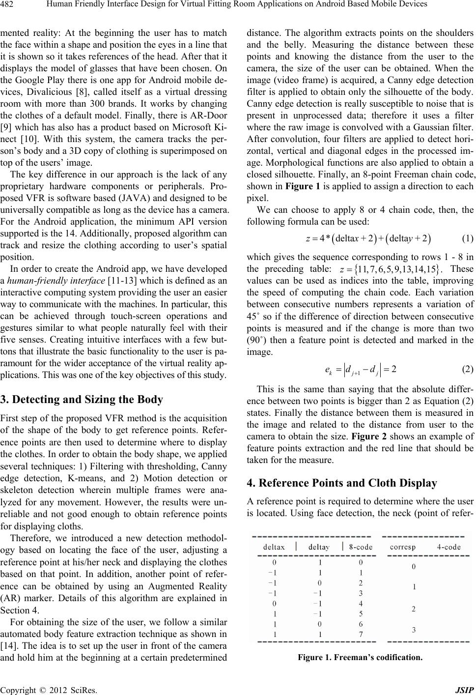
closed silhouette. Finally, an 8-point Freeman chain code,
shown in Figure 1 is applied to assign a direction to each
pixel.
We can choose to apply 8 or 4 chain code, then, the
following formula can be used:
4 delta2delta2z *x + + y + (1)
which gives the sequence corresponding to rows 1 - 8 in
the preceding table:
11,7,6,5,9,13,14,15 .z These
values can be used as indices into the table, improving
the speed of computing the chain code. Each variation
between consecutive numbers represents a variation of
45˚ so if the difference of direction between consecutive
points is measured and if the change is more than two
(90˚) then a feature point is detected and marked in the
image.
12
kj j
ed d
(2)
This is the same than saying that the absolute differ-
ence between two points is bigger than 2 as Equation (2)
states. Finally the distance between them is measured in
the image and related to the distance from user to the
camera to obtain the size. Figure 2 show s an example o f
feature points extraction and the red line that should be
taken for the measure.
4. Reference Points and Cloth Display
A reference point is required to determine where the user
is located. Using face detection, the neck (point of refer-
Figure 1. Freeman’s codification.
Copyright © 2012 SciRes. JSIP