Paper Menu >>
Journal Menu >>
 Journal of Signal and Information Processing, 2012, 3, 421-426 http://dx.doi.org/10.4236/jsip.2012.34055 Published Online November 2012 (http://www.SciRP.org/journal/jsip) Development of Digital-Controlled Measuring Instrument for Hearing Longcong Chen1, Gaiqin Liu2, Bin Gao1, Ping Chen1, Xingliang Xiong1* 1Laboratory of Forensic Medicine and Biomedical Information, Chongqing Medical University, Chongqing, China; 2School of Opto- electronic Information, Chongqing University of Technology, Chongqing, China. Email: *xxlsober@sina.com Received July 21st, 2012; revised August 27th, 2012; accepted September 5th, 2012 ABSTRACT A digital-controlled measuring instrument for hearing, which is mainly composed of STC11F16EX, AD9833, ISD4004- 16MS and LM1972, is introduced in this paper. It may output highly accurate and purified sine signal whose frequency and amplitude are controlled by digital data. Specially, the displaying number of decibel is equal to actual number of decibel because that frequency response of earphone is corrected through software of microcontroller. Additionally, touching buttons, which is simple and convenience to use, is selected. Hence this instrument is convenient to measure and teach about hearing specially, research and study on frequency characteristic of human ear and impedance charac- teristic of human body in medical science. Keywords: STC11F16EX; Digital-Controlled; Hearing; AD9833 1. Introduction As is known to all, sounds waves that human can hear have range not only in frequency from 20 Hz to 20 KHz, but also on intensity. Usually, hearing threshold of inten- sity includes two limited value: one is the maximum value named pain threshold, and the other is the mini- mum value called threshold of audibility [1]. The inten- sity between audibility and pain threshold is audibility range, and to same frequency sound waves, the larger sound intensity must sound louder, but for different fre- quencies of those, it is not necessarily sound stronger. Therefore, in order to obtain loudness level curve, we have to measure the sound intensity level of different frequency under the same loudness. And different per- sonal loudness curve is not completely same, that is to say, different people have different hearing. In practice, to measure personal hearing, different frequencies of pure sine and other signal are used to drive sound equipments, such as speakers, and earphone. The size of sound intensity level is usually utilized to measure hear- ing with decibels. Certainly, the instruments, which can output single frequent sound and other sound, are de- manded. In additionally, the auditory tests in the com- prehensive check-up for students, who prepare for higher school, college and university, are needed, and in the physical and medical teaching and research, the human hearing and impedance characteristics [2] are often de- manded. As a result, the needed generator should have the function of adjusting frequency and amplitude, and also can produce high precision and purity sine and other sound signals. Based on above, a novel instrument, which is mainly composed of STC11F16EX, AD9833, ISD4004-16MS and LM1972, is put forwarded. 2. Instrument Struction Design of the instrument includes two sides, hardware and software. Hardware is divided into nine parts: Micro- controller, voice signal generator, single frequency gen- erator, signal selector, audio fader amplifier, stereo audio power amplifier, keyboard, LCD monitor and power source circuit. The instrument block diagram is shown in Figure 1. This instrument mainly based on microcontroller and high-performance integrated chips, such as STC11- F16EX, ISD4004-16MS, AD9833 and so on, which not only can increase its intelligence, precision, stability, but also reduce its power consumption and volume. The mi- crocontroller, STC11F16EX, output all kinds of com- mand and data signal to control relative chips for gener- ating needed sound. In this instrument, ISD4004-16MS, which is act as voice signal generator and can record various sound under management of microprocessor, is applied to produce recorded audio sound, while AD9833, single frequency signal, is ued to generate single fre- s *Corresponding author. Copyright © 2012 SciRes. JSIP 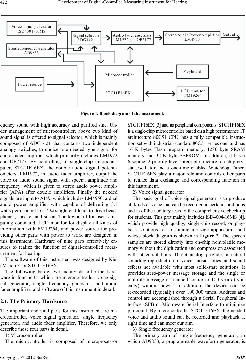 Development of Digital-Controlled Measuring Instrument for Hearing 422 Figure 1. Blo ck diagram of the instrument. quency sound with high accuracy and purified sine. Un- der management of microcontroller, above two kind of sound signal is offered to signal selector, which is mainly composed of ADG1421 that contains two independent analogy switches, to choice one needed type signal for audio fader amplifier which primarily includes LM1972 and OP2177. By controlling of single-chip microcom- puter, STC11F16EX, the double audio digital potenti- ometers, LM1972, in audio fader amplifier, output the voice or audio sound signal with special amplitude and frequency ,which is given to stereo audio power ampli- fier (APA) after double amplifiers. Finally the needed signals are input to APA, which includes LM4950, a dual audio power amplifier with capable of delivering 3.1 watts per channel to a 4 Ω single-end load, to drive head- phones, speaker and so on. The keyboard for user’s im- puting command, LCD monitor for display all kinds of information with FM19264, and power source for pro- viding other parts with power to work are designed in this instrument. Hardware of nine parts effectively en- sures to realize the function of digital-controlled meas- urement for hearing. The software of this instrument was designed by Kiel uVision 3 for STC11F16EX. The following below, we mainly describe the hard- ware in four parts, which are microcontroller, voice sig- nal generator, single frequency generator, and audio fader amplifier, and software of this instrument in detail. 2.1. The Primary Hardware The important and vital parts for this instrument are mi- crocontroller, voice signal generator, single frequency generator, and audio fader amplifier. Therefore, we only describe those four parts in detail. 1) Microcontroller The microcontroller is composed of microprocessor STC11F16EX [3] and its peripheral components. STC11F16EX is a single-chip microcontroller based on a high performance 1T architecture 80C51 CPU, has a fully compatible instruc- tion set with industrial-standard 80C51 series one, and has 16 K bytes Flash program memory, 1280 byte SRAM memory and 32 K byte EEPROM. In addition, it has a 6-source, 2-priority-level interrupt structure, on-chip cry- stal oscillator and a one-time enabled Watchdog Timer. STC11F16EX play a major role and controls other parts to realize data exchange and corresponding function in this instrument. 2) Voice signal generator The basic goal of voice signal generator is to produce all kinds of voice that can be recorded in certain conditions and is of the auditory tests in the comprehensive check-up for students. This part mainly includes ISD4004-16MS [4], which provide high quality, single-chip record, or play- back solutions for 16-minute message applications and whose block diagram is shown in Figure 2. The speech samples are stored directly into on-chip nonvolatile me- mory without the digitization and compression associated with other solutions. Direct analog provides a natural sounding reproduction of voice, music, tones, and sound effects not available with most solid-state solutions. It provides zero-power message storage and the single or multiple message is retained for up to 100 years (typi- cally) without power. In addition, the device can be re-recorded (typically) over 100,000 times. Address and control are accomplished through a Serial Peripheral In- terface (SPI) or Microware Serial Interface to minimize pin count. By microcontroller STC11F16EX, the needed voice and audio sound can be recorded and playback at right time and can meet our aim. 3) Single frequency generator The primary aim of single frequency generator, in which AD9833, a programmable waveform generator, is Copyright © 2012 SciRes. JSIP  Development of Digital-Controlled Measuring Instrument for Hearing 423 selected, is to generate single frequency sine signal for measuring loudness level curve, the human hearing and impedance characteristics. The AD9833 [5-7],whose func- tion block diagram is shown in Figure 3, is a low power, programmable waveform generator capable of producing sine, triangular, and square wave outputs. The frequency, phase and waveform of outputting signal are software programmable. The frequency registers are 28 bits wide. As the result, the output sine frequency is: 28 outputMCLK 2 f fK (1) where is the value loaded into the selected fre- quency register, means input clock rate. K MCLK Therefore, with a 1 MHz clock rate, the AD9833 can be tuned to 0.004 Hz resolution, and we can obtain single f frequency signal with enough high precision of fre- quency. Certainly, after STC11F16EX sends corresponding data to selected frequency register, we can get the needed frequency sine signal. 4) Audio fader amplifier For major target of getting needed signal whose ampli- tude meets our demand, a digitally controlled 2-channel audio attenuator—LM1972 [8] and a precision low noise, low input bias current operational amplifier—OP2177 are applied. The LM1972, whose function block diagram is shown in Figure 4, is a digitally controlled 2-channel 78 dB audio attenuator fabricated on a CMOS process. Figure 2. Function block diagram of ISD4004-16MS. Figure 3. Function block diagram of AD9833. Copyright © 2012 SciRes. JSIP 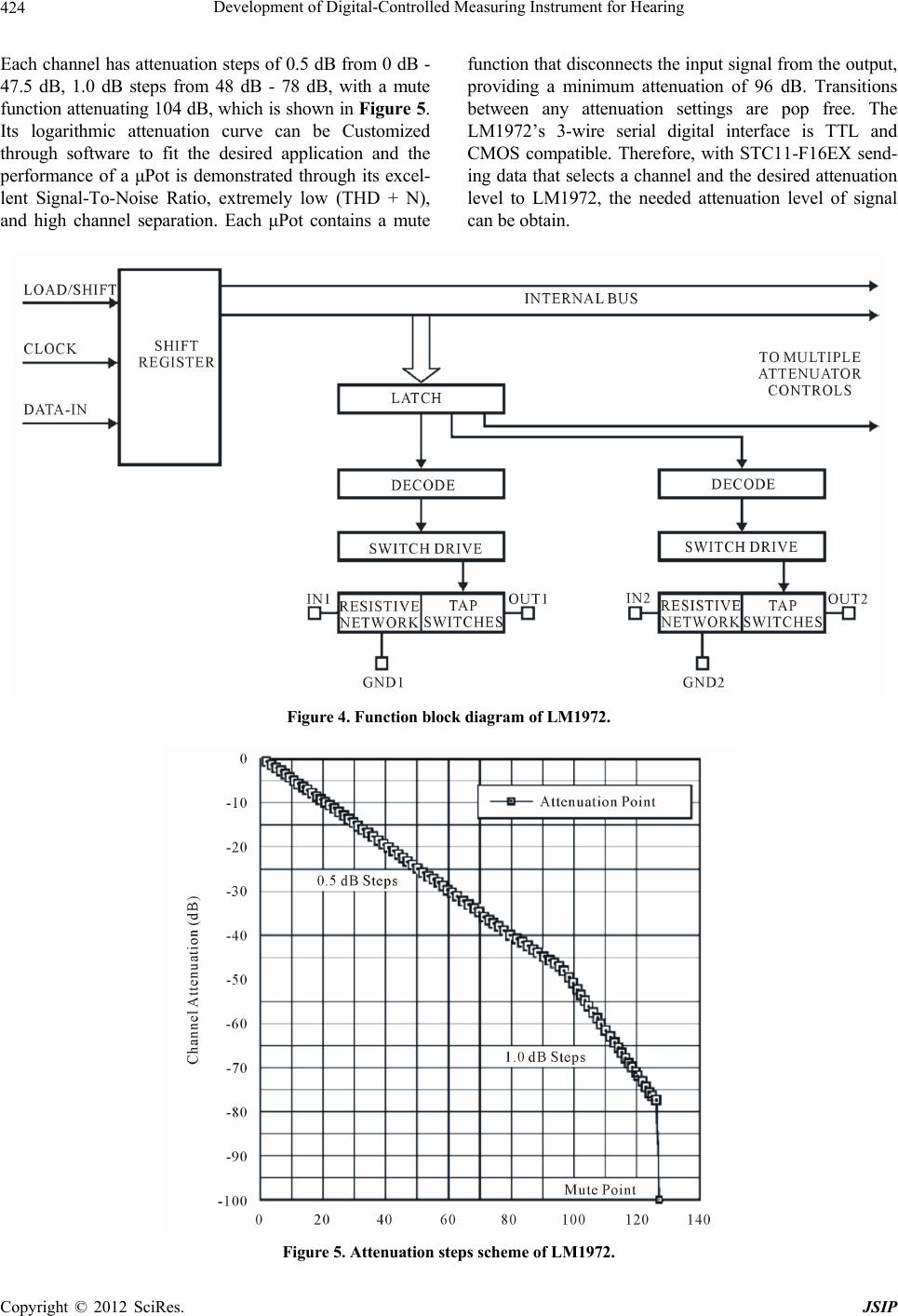 Development of Digital-Controlled Measuring Instrument for Hearing 424 Each channel has attenuation steps of 0.5 dB from 0 dB - 47.5 dB, 1.0 dB steps from 48 dB - 78 dB, with a mute function attenuating 104 dB, which is shown in Figure 5. Its logarithmic attenuation curve can be Customized through software to fit the desired application and the performance of a μPot is demonstrated through its excel- lent Signal-To-Noise Ratio, extremely low (THD + N), and high channel separation. Each μPot contains a mute function that disconnects the input signal from the output, providing a minimum attenuation of 96 dB. Transitions between any attenuation settings are pop free. The LM1972’s 3-wire serial digital interface is TTL and CMOS compatible. Therefore, with STC11-F16EX send- ing data that selects a channel and the desired attenuation level to LM1972, the needed attenuation level of signal can be obtain. Figure 4. Function block diagram of LM1972. Figure 5. Attenuation steps scheme of LM1972. Copyright © 2012 SciRes. JSIP 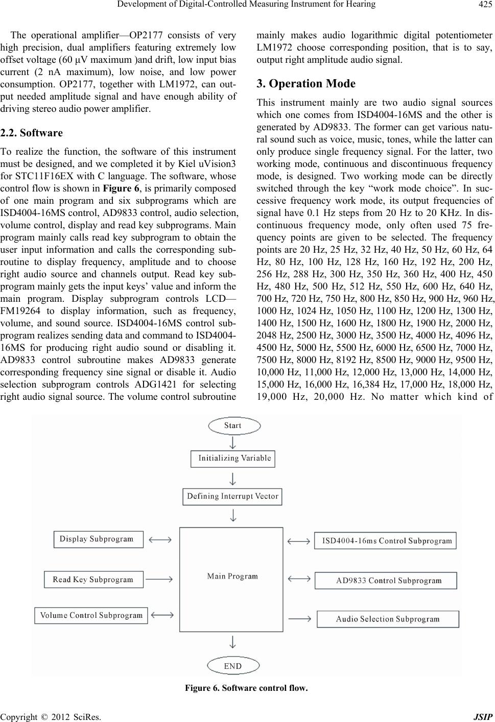 Development of Digital-Controlled Measuring Instrument for Hearing 425 The operational amplifier—OP2177 consists of very high precision, dual amplifiers featuring extremely low offset voltage (60 μV maximum )and drift, low input bias current (2 nA maximum), low noise, and low power consumption. OP2177, together with LM1972, can out- put needed amplitude signal and have enough ability of driving stereo audio power amplifier. 2.2. Software To realize the function, the software of this instrument must be designed, and we completed it by Kiel uVision3 for STC11F16EX with C language. The software, whose control flow is shown in Figure 6, is primarily composed of one main program and six subprograms which are ISD4004-16MS control, AD9833 control, audio selection, volume control, display and read key subprograms. Main program mainly calls read key subprogram to obtain the user input information and calls the corresponding sub- routine to display frequency, amplitude and to choose right audio source and channels output. Read key sub- program mainly gets the input keys’ value and inform the main program. Display subprogram controls LCD— FM19264 to display information, such as frequency, volume, and sound source. ISD4004-16MS control sub- program realizes sending data and command to ISD4004- 16MS for producing right audio sound or disabling it. AD9833 control subroutine makes AD9833 generate corresponding frequency sine signal or disable it. Audio selection subprogram controls ADG1421 for selecting right audio signal source. The volume control subroutine mainly makes audio logarithmic digital potentiometer LM1972 choose corresponding position, that is to say, output right amplitude audio signal. 3. Operation Mode This instrument mainly are two audio signal sources which one comes from ISD4004-16MS and the other is generated by AD9833. The former can get various natu- ral sound such as voice, music, tones, while the latter can only produce single frequency signal. For the latter, two working mode, continuous and discontinuous frequency mode, is designed. Two working mode can be directly switched through the key “work mode choice”. In suc- cessive frequency work mode, its output frequencies of signal have 0.1 Hz steps from 20 Hz to 20 KHz. In dis- continuous frequency mode, only often used 75 fre- quency points are given to be selected. The frequency points are 20 Hz, 25 Hz, 32 Hz, 40 Hz, 50 Hz, 60 Hz, 64 Hz, 80 Hz, 100 Hz, 128 Hz, 160 Hz, 192 Hz, 200 Hz, 256 Hz, 288 Hz, 300 Hz, 350 Hz, 360 Hz, 400 Hz, 450 Hz, 480 Hz, 500 Hz, 512 Hz, 550 Hz, 600 Hz, 640 Hz, 700 Hz, 720 Hz, 750 Hz, 800 Hz, 850 Hz, 900 Hz, 960 Hz, 1000 Hz, 1024 Hz, 1050 Hz, 1100 Hz, 1200 Hz, 1300 Hz, 1400 Hz, 1500 Hz, 1600 Hz, 1800 Hz, 1900 Hz, 2000 Hz, 2048 Hz, 2500 Hz, 3000 Hz, 3500 Hz, 4000 Hz, 4096 Hz, 4500 Hz, 5000 Hz, 5500 Hz, 6000 Hz, 6500 Hz, 7000 Hz, 7500 Hz, 8000 Hz, 8192 Hz, 8500 Hz, 9000 Hz, 9500 Hz, 10,000 Hz, 11,000 Hz, 12,000 Hz, 13,000 Hz, 14,000 Hz, 15,000 Hz, 16,000 Hz, 16,384 Hz, 17,000 Hz, 18,000 Hz, 19,000 Hz, 20,000 Hz. No matter which kind of Figure 6. Software control flow. Copyright © 2012 SciRes. JSIP  Development of Digital-Controlled Measuring Instrument for Hearing 426 work mode, it is no influence for volume adjustment, but for different frequencies, the ranges of output sound volume have different decibels values, this is to say, the scope is different for different frequencies because head- set of audio has not same response to different ones, and microcontroller program made a corresponding modifi- cation. 4. Disussions and Conclusions This instrument adopts single-chip control and high- performance sine waveform, so, it can output high preci- sion frequency (frequency error < 0.004 Hz) and high purity pure single audio sound, and applied LCD to dis- play all kinds of information. This instrument equipped with two kinds of sound sources, therefore, it is conven- ient for the audio test and experiment. In addition, all kinds of control and choices are application of electronic switch without mechanical contact, by using in practical, it is not only convenient operation, simple, and working stability and reliability is extremely high. Certainly, this instrument can be used as high-preci- sion frequency and high-drive sinusoidal signal source for research and teaching in testing human impedance characteristics. In a word, this instrument has very good novelty and practicability. Additionally, touching buttons, which is simple and convenience to use, is selected. Hence this instrument is convenient to measure and teach about hearing specially, research and study on frequency char- acteristic of human ear and impedance characteristic of human body in medical science. REFERENCES [1] E. Gong and P. Gan, “Medical Physics,” 2nd Edition, Science Press, Beijing, 2004. [2] D. W. Kim, H. S. Kim, D. H. Lee, et al., “Importance of Skin Resistance in the Reverse Iontophresis-Based Non- Invasive Glucose Monitoring System,” Proceedings of the 26th Annual International Conference of the IEEE Engineering in Medicine and Biology Society, Vol. 4, 2004, pp. 2434-2437. [3] STC MCU Limited, “STC11F/10Fxx series MCU & STC11F/ 10Lxx Series MCU Data Sheet,” 2012. http://www.mcu-memory.com/datasheet/stc/STC-AD-PD F/STC11F-10Fxx-english.pdf [4] Nuvoton Technology Corporation, “ISD4004 SERIES,” 2012. http://www.nuvoton.com/hq/enu/ProductAndSales/Product Lines/ConsumerElectronicsIC/ISDVoiceIC/ISDChipCord er/Documents/ISD4004.pdf [5] Analog Devices, “Low Power, 12.65 mW, 2.3 V to 5.5 V, Programmable Waveform Generator AD9833,” 2012. http://www.analog.com/static/imported-files/data_sheets/ AD9833.pdf [6] G. L. Liu, L. Q. Liao and J. P. Shi, “Programmable Wave- Form Generator AD9833 and Its Application,” Interna- tional Electronic Elements, June 2006, pp. 44-47. [7] M. C. Liu, J. R. Sun and J. C. Wu, “Application and De- sign of Signal Generator Based on DDS Chip,” Journal of Tianjin Normal University, Vol. 28, No. 4, 2008, pp. 66- 68. [8] Texas Instruments, “LM1972 μPot™ 2-Channel 78 dB Audio Attenuator with Mute,” 2012. http://www.national.com/ds/LM/LM1972.pdf Copyright © 2012 SciRes. JSIP |

