Paper Menu >>
Journal Menu >>
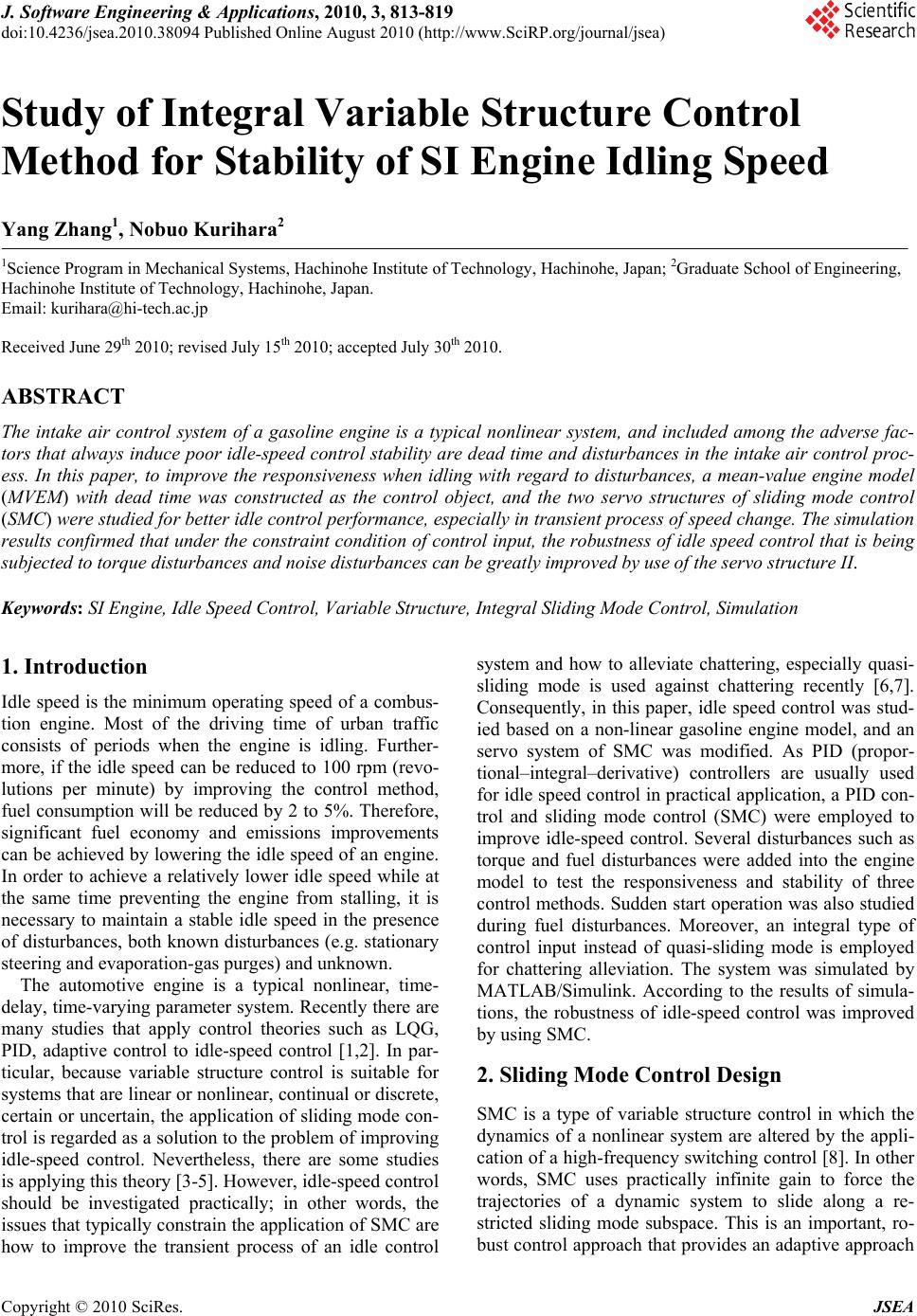 J. Software Engineering & Applications, 2010, 3, 813-819 doi:10.4236/jsea.2010.38094 Published Online August 2010 (http://www.SciRP.org/journal/jsea) Copyright © 2010 SciRes. JSEA 813 Study of Integral Variable Structure Control Method for Stability of SI Engine Idling Speed Yang Zhang1, Nobuo Kurihara2 1Science Program in Mechanical Systems, Hachinohe Institute of Technology, Hachinohe, Japan; 2Graduate School of Engineering, Hachinohe Institute of Technology, Hachinohe, Japan. Email: kurihara@hi-tech.ac.jp Received June 29th 2010; revised July 15th 2010; accepted July 30th 2010. ABSTRACT The intake air control system of a gasoline engine is a typical nonlinear system, and included among the adverse fac- tors that always induce poor idle-speed control stability are dead time and disturbances in the intake air control proc- ess. In this paper, to improve the responsiveness when idling with regard to disturbances, a mean-value engine model (MVEM) with dead time was constructed as the control object, and the two servo structures of sliding mode control (SMC) were studied for better idle control performance, especially in transient process of speed change. The simulation results confirmed that under the constraint condition of control input, the robustness of idle speed control that is being subjected to torque disturbances and noise disturbances can be greatly improved by use of the servo structure II. Keywords: SI Engine, Idle Speed Control, Variable Structure, Integral Sliding Mode Control, Simulation 1. Introduction Idle speed is the minimum operating speed of a combus- tion engine. Most of the driving time of urban traffic consists of periods when the engine is idling. Further- more, if the idle speed can be reduced to 100 rpm (revo- lutions per minute) by improving the control method, fuel consumption will be reduced by 2 to 5%. Therefore, significant fuel economy and emissions improvements can be achieved by lowering the idle speed of an engine. In order to achieve a relatively lower idle speed while at the same time preventing the engine from stalling, it is necessary to maintain a stable idle speed in the presence of disturbances, both known disturbances (e.g. stationary steering and evaporation-gas purges) and unknown. The automotive engine is a typical nonlinear, time- delay, time-varying parameter system. Recently there are many studies that apply control theories such as LQG, PID, adaptive control to idle-speed control [1,2]. In par- ticular, because variable structure control is suitable for systems that are linear or nonlinear, continual or discrete, certain or uncertain, the application of sliding mode con- trol is regarded as a solution to the problem of improving idle-speed control. Nevertheless, there are some studies is applying this theory [3-5]. However, idle-speed control should be investigated practically; in other words, the issues that typically constrain the application of SMC are how to improve the transient process of an idle control system and how to alleviate chattering, especially quasi- sliding mode is used against chattering recently [6,7]. Consequently, in this paper, idle speed control was stud- ied based on a non-linear gasoline engine model, and an servo system of SMC was modified. As PID (propor- tional–integral–derivative) controllers are usually used for idle speed control in practical application, a PID con- trol and sliding mode control (SMC) were employed to improve idle-speed control. Several disturbances such as torque and fuel disturbances were added into the engine model to test the responsiveness and stability of three control methods. Sudden start operation was also studied during fuel disturbances. Moreover, an integral type of control input instead of quasi-sliding mode is employed for chattering alleviation. The system was simulated by MATLAB/Simulink. According to the results of simula- tions, the robustness of idle-speed control was improved by using SMC. 2. Sliding Mode Control Design SMC is a type of variable structure control in which the dynamics of a nonlinear system are altered by the appli- cation of a high-frequency switching control [8]. In other words, SMC uses practically infinite gain to force the trajectories of a dynamic system to slide along a re- stricted sliding mode subspace. This is an important, ro- bust control approach that provides an adaptive approach 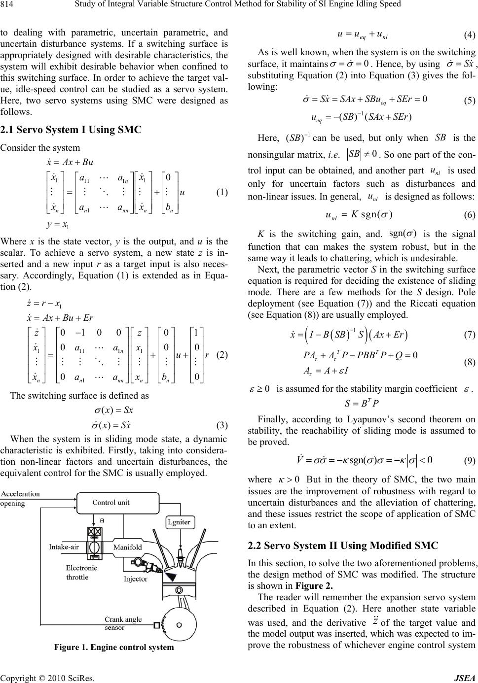 Study of Integral Variable Structure Control Method for Stability of SI Engine Idling Speed Copyright © 2010 SciRes. JSEA 814 to dealing with parametric, uncertain parametric, and uncertain disturbance systems. If a switching surface is appropriately designed with desirable characteristics, the system will exhibit desirable behavior when confined to this switching surface. In order to achieve the target val- ue, idle-speed control can be studied as a servo system. Here, two servo systems using SMC were designed as follows. 2.1 Servo System I Using SMC Consider the system x Ax Bu 11 11 1 1 0 n nn nnnn xx aa u xa axb (1) 1 yx Where x is the state vector, y is the output, and u is the scalar. To achieve a servo system, a new state z is in- serted and a new input r as a target input is also neces- sary. Accordingly, Equation (1) is extended as in Equa- tion (2). 1 zrx x Ax BuEr 11111 1 01000 1 00 0 00 n nnnnnn zz xaax ur xaaxb (2) The switching surface is defined as () x Sx () x Sx (3) When the system is in sliding mode state, a dynamic characteristic is exhibited. Firstly, taking into considera- tion non-linear factors and uncertain disturbances, the equivalent control for the SMC is usually employed. Figure 1. Engine control system eq nl uu u (4) As is well known, when the system is on the switching surface, it maintains0 . Hence, by using Sx , substituting Equation (2) into Equation (3) gives the fol- lowing: 0 eq SxSAx SBuSEr (5) 1 ()( ) eq uSBSAxSEr Here, 1 ()SB can be used, but only when SB is the nonsingular matrix, i.e. 0SB . So one part of the con- trol input can be obtained, and another part nl u is used only for uncertain factors such as disturbances and non-linear issues. In general, nl u is designed as follows: sgn( ) nl uK (6) K is the switching gain, and. sgn( ) is the signal function that can makes the system robust, but in the same way it leads to chattering, which is undesirable. Next, the parametric vector S in the switching surface equation is required for deciding the existence of sliding mode. There are a few methods for the S design. Pole deployment (see Equation (7)) and the Riccati equation (see Equation (8)) are usually employed. 1 x IBSB SAxEr (7) 0 TT PAAPPBB PQ AAI (8) 0 is assumed for the stability margin coefficient . T SBP Finally, according to Lyapunov’s second theorem on stability, the reachability of sliding mode is assumed to be proved. sgn( )0V (9) where 0 But in the theory of SMC, the two main issues are the improvement of robustness with regard to uncertain disturbances and the alleviation of chattering, and these issues restrict the scope of application of SMC to an extent. 2.2 Servo System II Using Modified SMC In this section, to solve the two aforementioned problems, the design method of SMC was modified. The structure is shown in Figure 2. The reader will remember the expansion servo system described in Equation (2). Here another state variable was used, and the derivative z of the target value and the model output was inserted, which was expected to im- prove the robustness of whichever engine control system 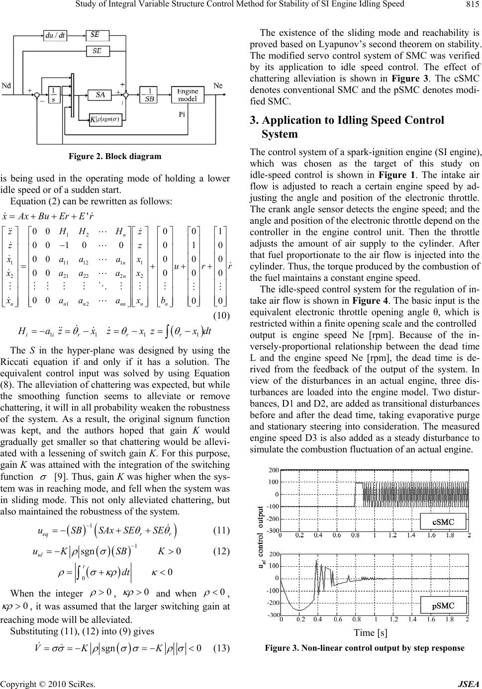 Study of Integral Variable Structure Control Method for Stability of SI Engine Idling Speed Copyright © 2010 SciRes. JSEA 815 Figure 2. Block diagram is being used in the operating mode of holding a lower idle speed or of a sudden start. Equation (2) can be rewritten as follows: ' x AxBuErEr 12 1111211 2212222 12 000 0 001 0001 000 0 000 0 00 0 n n n nnnnnnn zHHHz zz xaaax u xaaax xaaaxb 1 0 0 0 0 rr (10) 1ii H a 1r zx 1r zx 1r zxdt The S in the hyper-plane was designed by using the Riccati equation if and only if it has a solution. The equivalent control input was solved by using Equation (8). The alleviation of chattering was expected, but while the smoothing function seems to alleviate or remove chattering, it will in all probability weaken the robustness of the system. As a result, the original signum function was kept, and the authors hoped that gain K would gradually get smaller so that chattering would be allevi- ated with a lessening of switch gain K. For this purpose, gain K was attained with the integration of the switching function [9]. Thus, gain K was higher when the sys- tem was in reaching mode, and fell when the system was in sliding mode. This not only alleviated chattering, but also maintained the robustness of the system. 1 eqr r uSBSAx SESE (11) 1 sgn 0 nl uKSB K (12) 00 tdt When the integer 0 , 0 and when 0 , 0 , it was assumed that the larger switching gain at reaching mode will be alleviated. Substituting (11), (12) into (9) gives sgn 0VK K (13) The existence of the sliding mode and reachability is proved based on Lyapunov’s second theorem on stability. The modified servo control system of SMC was verified by its application to idle speed control. The effect of chattering alleviation is shown in Figure 3. The cSMC denotes conventional SMC and the pSMC denotes modi- fied SMC. 3. Application to Idling Speed Control System The control system of a spark-ignition engine (SI engine), which was chosen as the target of this study on idle-speed control is shown in Figure 1. The intake air flow is adjusted to reach a certain engine speed by ad- justing the angle and position of the electronic throttle. The crank angle sensor detects the engine speed; and the angle and position of the electronic throttle depend on the controller in the engine control unit. Then the throttle adjusts the amount of air supply to the cylinder. After that fuel proportionate to the air flow is injected into the cylinder. Thus, the torque produced by the combustion of the fuel maintains a constant engine speed. The idle-speed control system for the regulation of in- take air flow is shown in Figure 4. The basic input is the equivalent electronic throttle opening angle θ, which is restricted within a finite opening scale and the controlled output is engine speed Ne [rpm]. Because of the in- versely-proportional relationship between the dead time L and the engine speed Ne [rpm], the dead time is de- rived from the feedback of the output of the system. In view of the disturbances in an actual engine, three dis- turbances are loaded into the engine model. Two distur- bances, D1 and D2, are added as transitional disturbances before and after the dead time, taking evaporative purge and stationary steering into consideration. The measured engine speed D3 is also added as a steady disturbance to simulate the combustion fluctuation of an actual engine. Figure 3. Non-linear control output by step response Time [s] 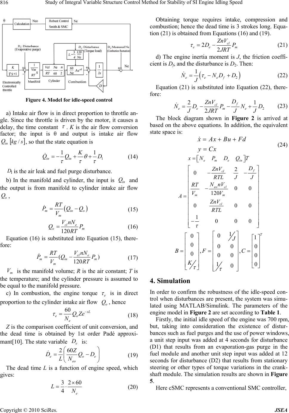 Study of Integral Variable Structure Control Method for Stability of SI Engine Idling Speed Copyright © 2010 SciRes. JSEA 816 Figure 4. Model for idle-speed control a) Intake air flow is in direct proportion to throttle an- gle. Since the throttle is driven by the motor, it causes a delay, the time constant . K is the air flow conversion factor; the input is θ and output is intake air flow in Q skg /, so that the state equation is 1 11 in in K QQ D (14) 1 Dis the air leak and fuel purge disturbance. b) In the manifold and cylinder, the input is in Q and the output is from manifold to cylinder intake air flow o Q, mino m RT PQQ V (15) 120 cl e om VnN QP RT (16) Equation (16) is substituted into Equation (15), there- fore: () 120 cl e minm m VnN RT PQ P VRT (17) m V is the manifold volume; R is the air constant; T is the temperature; and the cylinder pressure is assumed to be equal to the manifold pressure. c) In combustion, the engine torque e is in direct proportion to the cylinder intake air flow o Q, hence 60 s L eo e QZe N (18) Z is the comparison coefficient of unit conversion, and the dead time is obtained by 1st order Padé approxi- mant[10]. The state variable e D is: 260 eoe eo Z DQD LN (19) The dead time L is a function of engine speed, which gives: 32 60 4e LN (20) Obtaining torque requires intake, compression and combustion; hence the dead time is 3 strokes long. Equa- tion (21) is obtained from Equations (16) and (19). 22 cl ee m ZnV DP JRT (21) d) The engine inertia moment is J, the friction coeffi- cient is Df, and the disturbance is D2. Then: 2 1 eeef NNDD J (22) Equation (21) is substituted into Equation (22), there- fore: 2 21 2 f cl eem e D ZnV NDP ND JJRTJJ (23) The block diagram shown in Figure 2 is arrived at based on the above equations. In addition, the equivalent state space is: x Ax BuFd yCx (24) emein x NPDQT 2 0 00 120 000 1000 f cl eo cl mm cl D ZnV R TL JJ NnV RT VV A ZnV RTL 1 0 01 000 0 ,, 000 0 10 0 T J BFC K 4. Simulation In order to confirm the robustness of the idle-speed con- trol when disturbances are present, the system was simu- lated using MATLAB/Simulink. The parameters of the engine model in Figure 2 are set according to Table 1. Firstly, the initial idle speed of the engine was 700 rpm, but, taking into consideration the existence of distur- bances such as fuel purges and the use of power windows, a unit step input was added at 4 seconds for disturbance (D1) that results from an evaporation-gas purge in the fuel module and another unit step input was added at 12 seconds for disturbance (D2) that results from stationary steering or other types of torque variations in the crank- shaft module. The simulation results are shown in Figure 5. Here cSMC represents a conventional SMC controller, 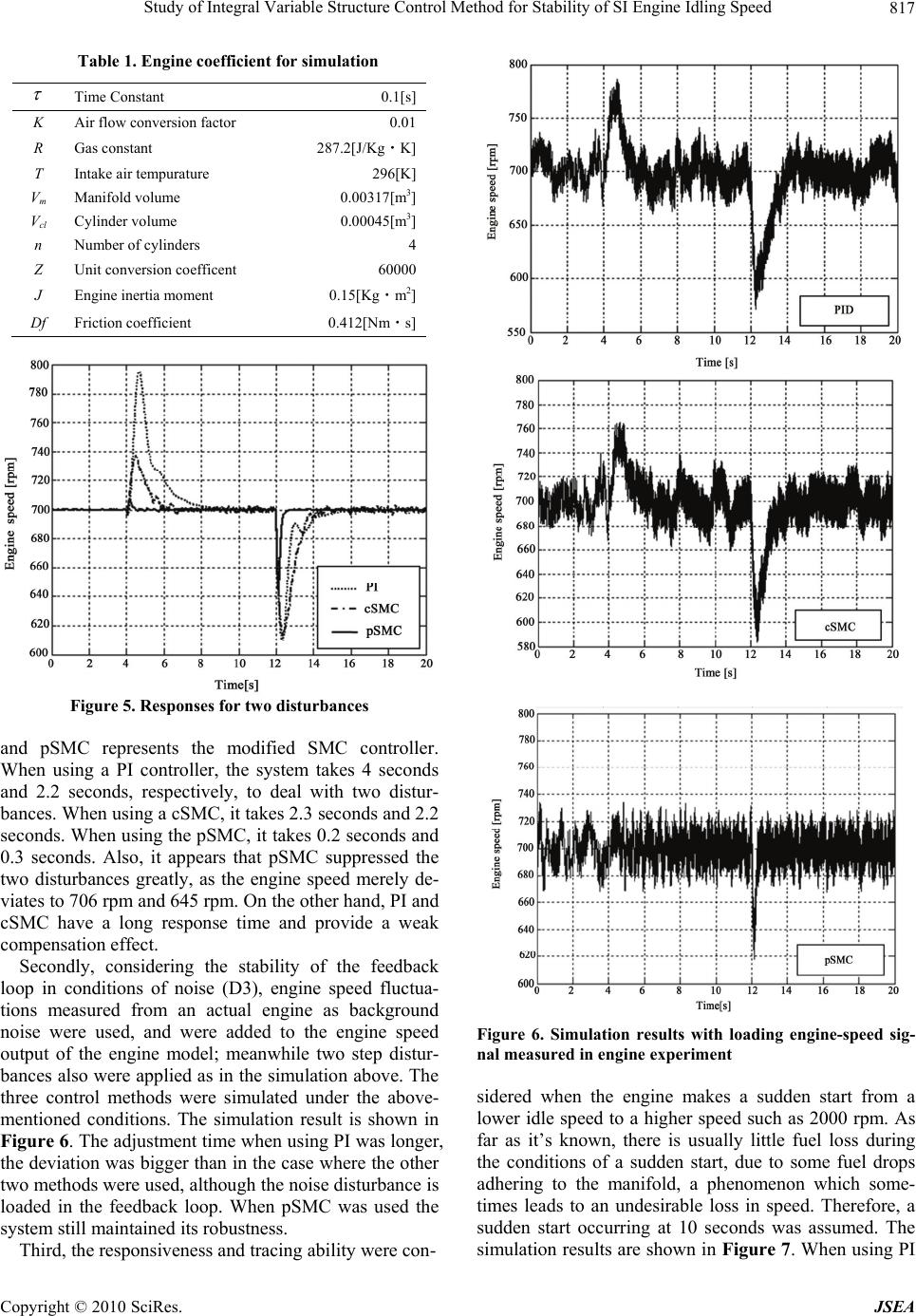 Study of Integral Variable Structure Control Method for Stability of SI Engine Idling Speed Copyright © 2010 SciRes. JSEA 817 Table 1. Engine coefficient for simulation Time Constant 0.1[s] K Air flow conversion factor 0.01 R Gas constant 287.2[J/Kg・K] T Intake air tempurature 296[K] Vm Manifold volume 0.00317[m3] Vcl Cylinder volume 0.00045[m3] n Number of cylinders 4 Z Unit conversion coefficent 60000 J Engine inertia moment 0.15[Kg・m2] Df Friction coefficient 0.412[Nm・s] Figure 5. Responses for two disturbances and pSMC represents the modified SMC controller. When using a PI controller, the system takes 4 seconds and 2.2 seconds, respectively, to deal with two distur- bances. When using a cSMC, it takes 2.3 seconds and 2.2 seconds. When using the pSMC, it takes 0.2 seconds and 0.3 seconds. Also, it appears that pSMC suppressed the two disturbances greatly, as the engine speed merely de- viates to 706 rpm and 645 rpm. On the other hand, PI and cSMC have a long response time and provide a weak compensation effect. Secondly, considering the stability of the feedback loop in conditions of noise (D3), engine speed fluctua- tions measured from an actual engine as background noise were used, and were added to the engine speed output of the engine model; meanwhile two step distur- bances also were applied as in the simulation above. The three control methods were simulated under the above- mentioned conditions. The simulation result is shown in Figure 6. The adjustment time when using PI was longer, the deviation was bigger than in the case where the other two methods were used, although the noise disturbance is loaded in the feedback loop. When pSMC was used the system still maintained its robustness. Third, the responsiveness and tracing ability were con- Figure 6. Simulation results with loading engine-speed sig- nal measured in engine experiment sidered when the engine makes a sudden start from a lower idle speed to a higher speed such as 2000 rpm. As far as it’s known, there is usually little fuel loss during the conditions of a sudden start, due to some fuel drops adhering to the manifold, a phenomenon which some- times leads to an undesirable loss in speed. Therefore, a sudden start occurring at 10 seconds was assumed. The simulation results are shown in Figure 7. When using PI 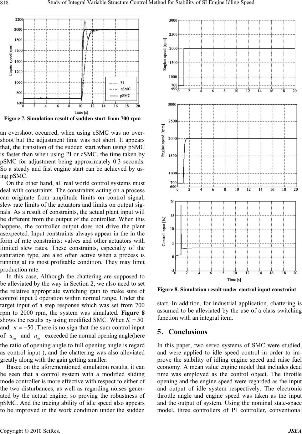 Study of Integral Variable Structure Control Method for Stability of SI Engine Idling Speed Copyright © 2010 SciRes. JSEA 818 Figure 7. Simulation result of sudden start from 700 rpm an overshoot occurred, when using cSMC was no over- shoot but the adjustment time was not short. It appears that, the transition of the sudden start when using pSMC is faster than when using PI or cSMC, the time taken by pSMC for adjustment being approximately 0.3 seconds. So a steady and fast engine start can be achieved by us- ing pSMC. On the other hand, all real world control systems must deal with constraints. The constraints acting on a process can originate from amplitude limits on control signal, slew rate limits of the actuators and limits on output sig- nals. As a result of constraints, the actual plant input will be different from the output of the controller. When this happens, the controller output does not drive the plant asexpected. Input constraints always appear in the in the form of rate constraints: valves and other actuators with limited slew rates. These constraints, especially of the saturation type, are also often active when a process is running at its most profitable condition. They may limit production rate. In this case, Although the chattering are supposed to be alleviated by the way in Section 2, we also need to set the relative appropriate switching gain to make sure of control input θ operation within normal range. Under the target input of a step response which was set from 700 rpm to 2000 rpm, the system was simulated. Figure 8 shows the results by using modified SMC. When50K and 50 ,There is no sign that the sum control input of eq u and nl u exceeded the normal opening angle(here the ratio of opening angle to full opening angle is regard as control input ), and the chattering was also alleviated greatly along with the gain getting smaller. Based on the aforementioned simulation results, it can be seen that a control system with a modified sliding mode controller is more effective with respect to either of the two disturbances, as well as regarding noises gener- ated by the actual engine, so proving the robustness of pSMC. And the tracing ability of idle speed also appears to be improved in the work condition under the sudden Figure 8. Simulation result under control input constraint start. In addition, for industrial application, chattering is assumed to be alleviated by the use of a class switching function with an integral item. 5.Conclusions In this paper, two servo systems of SMC were studied, and were applied to idle speed control in order to im- prove the stability of idling engine speed and raise fuel economy. A mean value engine model that includes dead time was employed as the control object. The throttle opening and the engine speed were regarded as the input and output of idle system respectively. The electronic throttle angle and engine speed was taken as the input and the output of system. Using the nominal state-space model, three controllers of PI controller, conventional 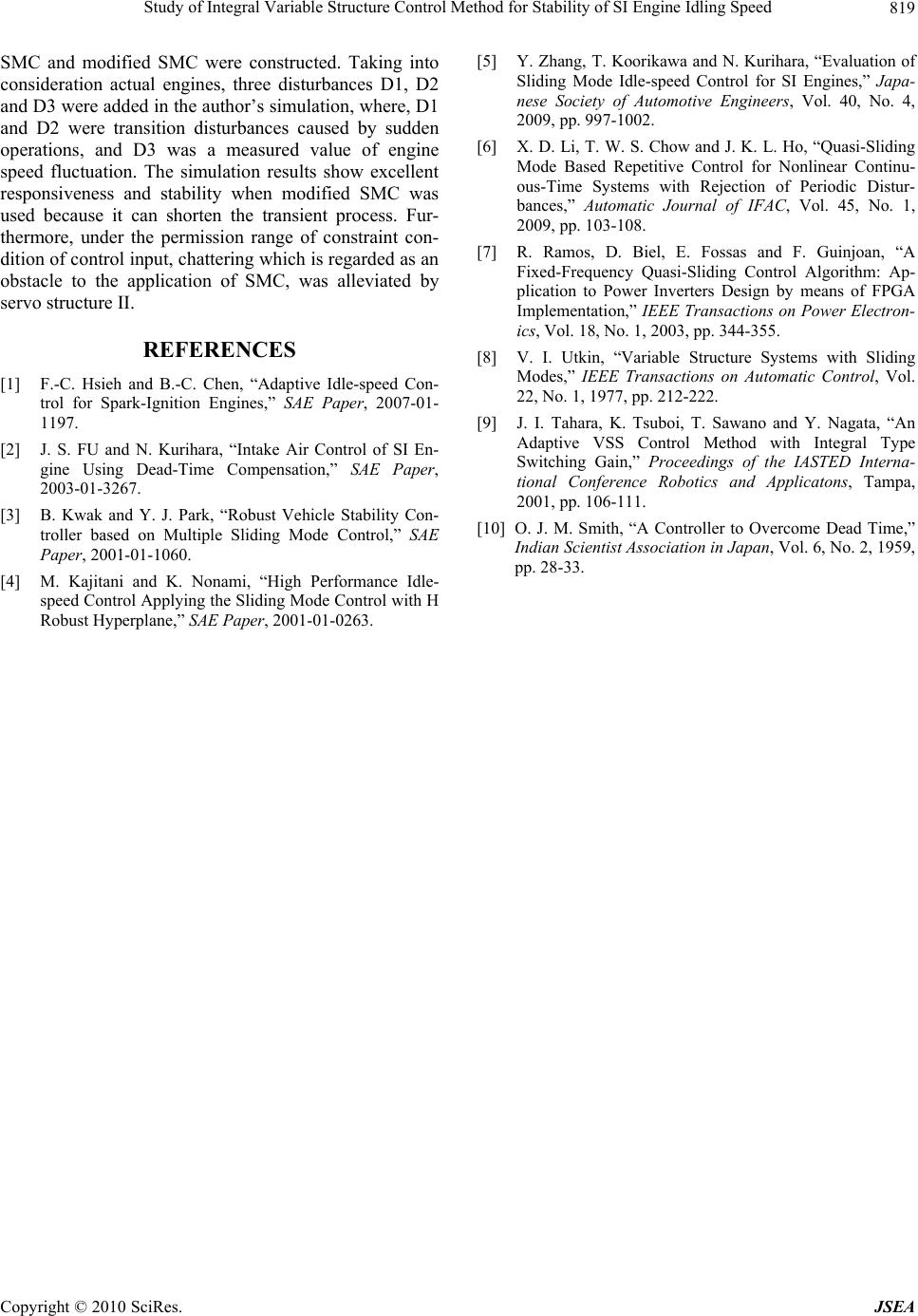 Study of Integral Variable Structure Control Method for Stability of SI Engine Idling Speed Copyright © 2010 SciRes. JSEA 819 SMC and modified SMC were constructed. Taking into consideration actual engines, three disturbances D1, D2 and D3 were added in the author’s simulation, where, D1 and D2 were transition disturbances caused by sudden operations, and D3 was a measured value of engine speed fluctuation. The simulation results show excellent responsiveness and stability when modified SMC was used because it can shorten the transient process. Fur- thermore, under the permission range of constraint con- dition of control input, chattering which is regarded as an obstacle to the application of SMC, was alleviated by servo structure II. REFERENCES [1] F.-C. Hsieh and B.-C. Chen, “Adaptive Idle-speed Con- trol for Spark-Ignition Engines,” SAE Paper, 2007-01- 1197. [2] J. S. FU and N. Kurihara, “Intake Air Control of SI En- gine Using Dead-Time Compensation,” SAE Paper, 2003-01-3267. [3] B. Kwak and Y. J. Park, “Robust Vehicle Stability Con- troller based on Multiple Sliding Mode Control,” SAE Paper, 2001-01-1060. [4] M. Kajitani and K. Nonami, “High Performance Idle- speed Control Applying the Sliding Mode Control with H Robust Hyperplane,” SAE Paper, 2001-01-0263. [5] Y. Zhang, T. Koorikawa and N. Kurihara, “Evaluation of Sliding Mode Idle-speed Control for SI Engines,” Japa- nese Society of Automotive Engineers, Vol. 40, No. 4, 2009, pp. 997-1002. [6] X. D. Li, T. W. S. Chow and J. K. L. Ho, “Quasi-Sliding Mode Based Repetitive Control for Nonlinear Continu- ous-Time Systems with Rejection of Periodic Distur- bances,” Automatic Journal of IFAC, Vol. 45, No. 1, 2009, pp. 103-108. [7] R. Ramos, D. Biel, E. Fossas and F. Guinjoan, “A Fixed-Frequency Quasi-Sliding Control Algorithm: Ap- plication to Power Inverters Design by means of FPGA Implementation,” IEEE Transactions on Power Electron- ics, Vol. 18, No. 1, 2003, pp. 344-355. [8] V. I. Utkin, “Variable Structure Systems with Sliding Modes,” IEEE Transactions on Automatic Control, Vol. 22, No. 1, 1977, pp. 212-222. [9] J. I. Tahara, K. Tsuboi, T. Sawano and Y. Nagata, “An Adaptive VSS Control Method with Integral Type Switching Gain,” Proceedings of the IASTED Interna- tional Conference Robotics and Applicatons, Tampa, 2001, pp. 106-111. [10] O. J. M. Smith, “A Controller to Overcome Dead Time,” Indian Scientist Association in Japan, Vol. 6, No. 2, 1959, pp. 28-33. |