Paper Menu >>
Journal Menu >>
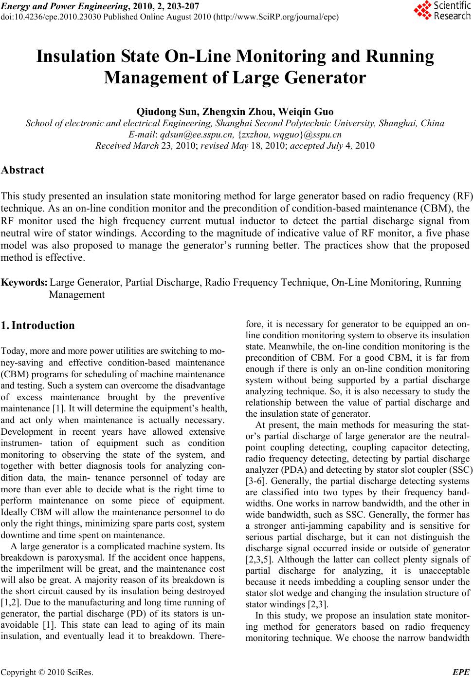 Energy and Power En gineering, 2010, 2, 203-207 doi:10.4236/epe.2010.23030 Published Online August 2010 (http://www.SciRP.org/journal/epe) Copyright © 2010 SciRes. EPE Insulation State On-Line Monitoring and Running Management of Large Generator Qiudong Sun, Zhengxin Zhou, Weiqin Guo School of electronic and electrical Engineering, Shanghai Second Polytechnic University, Shanghai, China E-mail: qdsun@ee.sspu.cn, {zxzhou, wqguo}@sspu.cn Received March 23, 2010; revised May 18, 2010; accepted July 4, 2010 Abstract This study presented an insulation state monitoring method for large generator based on radio frequency (RF) technique. As an on-line condition monitor and the precondition of condition-based maintenance (CBM), the RF monitor used the high frequency current mutual inductor to detect the partial discharge signal from neutral wire of stator windings. According to the magnitude of indicative value of RF monitor, a five phase model was also proposed to manage the generator’s running better. The practices show that the proposed method is effective. Keywords: Large Generator, Partial Discharge, Radio Frequency Technique, On-Line Monitoring, Running Management 1. Introduction Today, more and more power utilities are switching to mo- ney-saving and effective condition-based maintenance (CBM) programs for scheduling of machine maintenance and testing. Such a system can overcome the disadvantage of excess maintenance brought by the preventive maintenance [1]. It will determine the equipment’s health, and act only when maintenance is actually necessary. Development in recent years have allowed extensive instrumen- tation of equipment such as condition monitoring to observing the state of the system, and together with better diagnosis tools for analyzing con- dition data, the main- tenance personnel of today are more than ever able to decide what is the right time to perform maintenance on some piece of equipment. Ideally CBM will allow the maintenance personnel to do only the right things, minimizing spare parts cost, system downtime and time spent on maintenance. A large generator is a complicated machine system. Its breakdown is paroxysmal. If the accident once happens, the imperilment will be great, and the maintenance cost will also be great. A majority reason of its breakdown is the short circuit caused by its insulation being destroyed [1,2]. Due to the manufacturing and long time running of generator, the partial discharge (PD) of its stators is un- avoidable [1]. This state can lead to aging of its main insulation, and eventually lead it to breakdown. There- fore, it is necessary for generator to be equipped an on- line condition monitoring system to observe its insulation state. Meanwhile, the on-line condition monitoring is the precondition of CBM. For a good CBM, it is far from enough if there is only an on-line condition monitoring system without being supported by a partial discharge analyzing technique. So, it is also necessary to study the relationship between the value of partial discharge and the insulation state of generator. At present, the main methods for measuring the stat- or’s partial discharge of large generator are the neutral- point coupling detecting, coupling capacitor detecting, radio frequency detecting, detecting by partial discharge analyzer (PDA) and detecting by stator slot coupler (SSC) [3-6]. Generally, the partial discharge detecting systems are classified into two types by their frequency band- widths. One works in narrow bandwidth, and the other in wide bandwidth, such as SSC. Generally, the former has a stronger anti-jamming capability and is sensitive for serious partial discharge, but it can not distinguish the discharge signal occurred inside or outside of generator [2,3,5]. Although the latter can collect plenty signals of partial discharge for analyzing, it is unacceptable because it needs imbedding a coupling sensor under the stator slot wedge and changing the insulation structure of stator windings [2,3]. In this study, we propose an insulation state monitor- ing method for generators based on radio frequency monitoring technique. We choose the narrow bandwidth 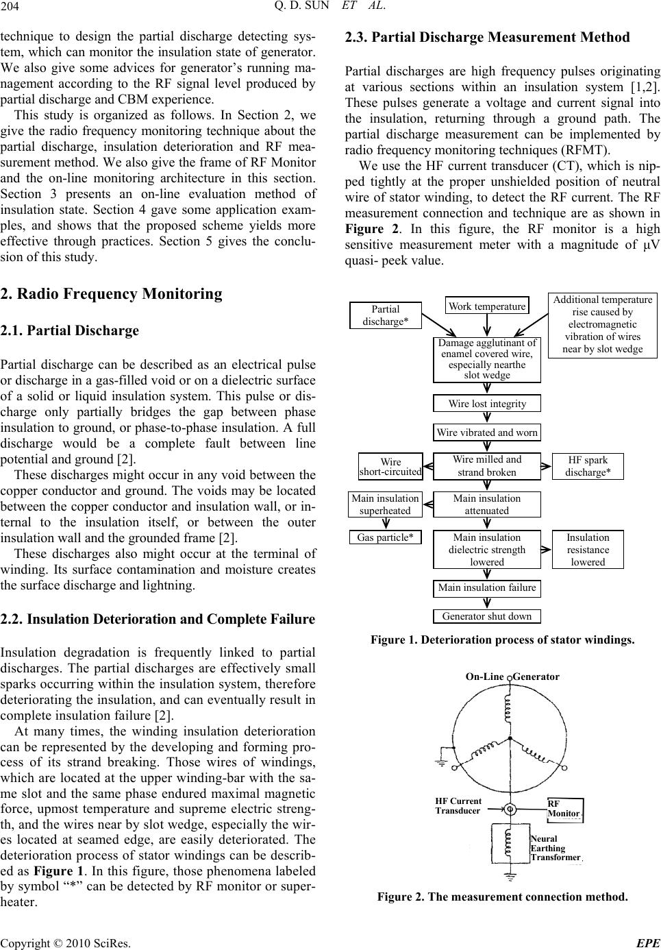 Q. D. SUN ET AL. Copyright © 2010 SciRes. EPE 204 technique to design the partial discharge detecting sys- tem, which can monitor the insulation state of generator. We also give some advices for generator’s running ma- nagement according to the RF signal level produced by partial discharge and CBM experience. This study is organized as follows. In Section 2, we give the radio frequency monitoring technique about the partial discharge, insulation deterioration and RF mea- surement method. We also give the frame of RF Monitor and the on-line monitoring architecture in this section. Section 3 presents an on-line evaluation method of insulation state. Section 4 gave some application exam- ples, and shows that the proposed scheme yields more effective through practices. Section 5 gives the conclu- sion of this study. 2. Radio Frequency Monitoring 2.1. Partial Discharge Partial discharge can be described as an electrical pulse or discharge in a gas-filled void or on a dielectric surface of a solid or liquid insulation system. This pulse or dis- charge only partially bridges the gap between phase insulation to ground, or phase-to-phase insulation. A full discharge would be a complete fault between line potential and ground [2]. These discharges might occur in any void between the copper conductor and ground. The voids may be located between the copper conductor and insulation wall, or in- ternal to the insulation itself, or between the outer insulation wall and the grounded frame [2]. These discharges also might occur at the terminal of winding. Its surface contamination and moisture creates the surface discharge and lightning. 2.2. Insulation Deterioration and Complete Failure Insulation degradation is frequently linked to partial discharges. The partial discharges are effectively small sparks occurring within the insulation system, therefore deteriorating the insulation, and can eventually result in complete insulation failure [2]. At many times, the winding insulation deterioration can be represented by the developing and forming pro- cess of its strand breaking. Those wires of windings, which are located at the upper winding-bar with the sa- me slot and the same phase endured maximal magnetic force, upmost temperature and supreme electric streng- th, and the wires near by slot wedge, especially the wir- es located at seamed edge, are easily deteriorated. The deterioration process of stator windings can be describ- ed as Figure 1. In this figure, those phenomena labeled by symbol “*” can be detected by RF monitor or super- heater. 2.3. Partial Discharge Measurement Method Partial discharges are high frequency pulses originating at various sections within an insulation system [1,2]. These pulses generate a voltage and current signal into the insulation, returning through a ground path. The partial discharge measurement can be implemented by radio frequency monitoring techniques (RFMT). We use the HF current transducer (CT), which is nip- ped tightly at the proper unshielded position of neutral wire of stator winding, to detect the RF current. The RF measurement connection and technique are as shown in Figure 2. In this figure, the RF monitor is a high sensitive measurement meter with a magnitude of μV quasi- peek value. Partial discharge* Work temperature Additional temperature rise caused by electromagnetic vibration of wires near by slot wedge Damage agglutinant of enamel covered wire, especially nearthe slot wedge Wire lost integrity Wire vibrated and worn Wire milled and strand broken Main insulation attenuated Wire short-circuited HF spark discharge* Main insulation superheated Gas particle*Main insulation dielectric strength lowered Main insulation failure Generator shut down Insulation resistance lowered Figure 1. Deterioration process of stator windings. On-Line Generator RF Monitor HF Current Transducer Neura l Earthing Transformer Figure 2. The measurement connection method. 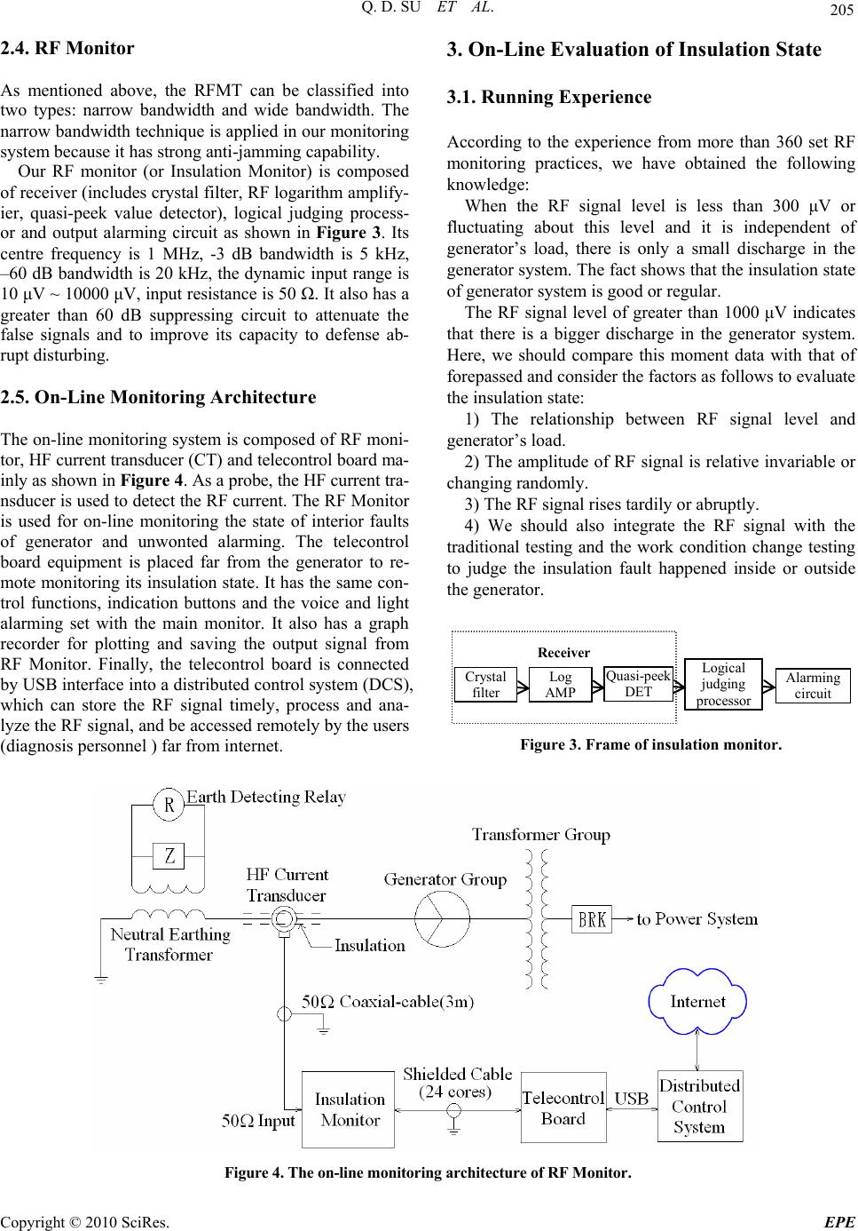 Q. D. SU ET AL. Copyright © 2010 SciRes. EPE 205 2.4. RF Monitor As mentioned above, the RFMT can be classified into two types: narrow bandwidth and wide bandwidth. The narrow bandwidth technique is applied in our monitoring system because it has strong anti-jamming capability. Our RF monitor (or Insulation Monitor) is composed of receiver (includes crystal filter, RF logarithm amplify- ier, quasi-peek value detector), logical judging process- or and output alarming circuit as shown in Figure 3. Its centre frequency is 1 MHz, -3 dB bandwidth is 5 kHz, –60 dB bandwidth is 20 kHz, the dynamic input range is 10 μV ~ 10000 μV, input resistance is 50 Ω. It also has a greater than 60 dB suppressing circuit to attenuate the false signals and to improve its capacity to defense ab- rupt disturbing. 2.5. On-Line Monitoring Architecture The on-line monitoring system is composed of RF moni- tor, HF current transducer (CT) and telecontrol board ma- inly as shown in Figure 4. As a probe, the HF current tra- nsducer is used to detect the RF current. The RF Monitor is used for on-line monitoring the state of interior faults of generator and unwonted alarming. The telecontrol board equipment is placed far from the generator to re- mote monitoring its insulation state. It has the same con- trol functions, indication buttons and the voice and light alarming set with the main monitor. It also has a graph recorder for plotting and saving the output signal from RF Monitor. Finally, the telecontrol board is connected by USB interface into a distributed control system (DCS), which can store the RF signal timely, process and ana- lyze the RF signal, and be accessed remotely by the users (diagnosis personnel ) far from internet. 3. On-Line Evaluation of Insulation State 3.1. Running Experience According to the experience from more than 360 set RF monitoring practices, we have obtained the following knowledge: When the RF signal level is less than 300 μV or fluctuating about this level and it is independent of generator’s load, there is only a small discharge in the generator system. The fact shows that the insulation state of generator system is good or regular. The RF signal level of greater than 1000 μV indicates that there is a bigger discharge in the generator system. Here, we should compare this moment data with that of forepassed and consider the factors as follows to evaluate the insulation state: 1) The relationship between RF signal level and generator’s load. 2) The amplitude of RF signal is relative invariable or changing randomly. 3) The RF signal rises tardily or abruptly. 4) We should also integrate the RF signal with the traditional testing and the work condition change testing to judge the insulation fault happened inside or outside the generator. Receiver Crystal filter Log AMP Quasi-peek DET Logical judging processo r Alarming circuit Figure 3. Frame of insulation monitor. Figure 4. The on-line monitoring arch itecture of RF Mon itor. 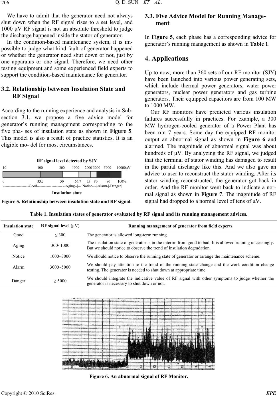 Q. D. SUN ET AL. Copyright © 2010 SciRes. EPE 206 We have to admit that the generator need not always shut down when the RF signal rises to a set level, and 1000 μV RF signal is not an absolute threshold to judge the discharge happened inside the stator of generator. In the condition-based maintenance system, it is im- possible to judge what kind fault of generator happened or whether the generator need shut down or not, just by one apparatus or one signal. Therefore, we need other testing equipment and some experienced field experts to support the condition-based maintenance for generator. 3.2. Relationship between Insulation State and RF Signal According to the running experience and analysis in Sub- section 3.1, we propose a five advice model for generator’s running management corresponding to the five pha- ses of insulation state as shown in Figure 5. This model is also a result of practice statistics. It is an eligible mo- del for most circumstances. RF signal level detected by SJY 10 100 300 1000 2000 3000 5000 10000V 0 33.3 50 66.7 75 80 90 100% |---------------------Good---------------------|--Aging--|--- Notice---|-Alarm-|-Danger| Insulation state Figure 5. Relationship between insulation state and RF signal. 3.3. Five Advice Model for Running Manage- ment In Figure 5, each phase has a corresponding advice for generator’s running management as shown in Table 1. 4. Applications Up to now, more than 360 sets of our RF monitor (SJY) have been launched into various power generating sets, which include thermal power generators, water power generators, nuclear power generators and gas turbine generators. Their equipped capacitors are from 100 MW to 1000 MW. Our RF monitors have predicted various insulation failures successfully in practices. For example, a 300 MW hydrogen-cooled generator of a Power Plant has been run 7 years. Some day the equipped RF monitor output an abnormal signal as shown in Figure 6 and alarmed. The magnitude of abnormal signal was about hundreds of μV. By analyzing the RF signal, we judged that the terminal of stator winding has damaged to result in the partial discharge like this. And we also gave an advice to user to reconstruct the stator winding. After its stator winding reconstructed, the generator got back in order. And the RF monitor went back to indicate a nor- mal signal as shown in Figure 7. The magnitude of RF signal had dropped to a normal level of tens of μV. Table 1. Insulation states of genera tor e v aluated by RF signal and its running management advices. Insulation state RF signal level (μV) Running management of generator from field experts Good ≤ 300 The generator is allowed long-term running. Aging 300~1000 The insulation state of generator is in the interim from good to bad. It is allowed running unceasingly. But we should notice to observe the trend of insulation degradation. Notice 1000~3000 We should notice to observe the running state of generator or arrange the maintenance scheme. Alarm 3000~5000 We should pay attention to the trend of the running state change and the work condition change testing. The generator is needed to shut down at appropriate time. Danger ≥ 5000 We should integrate the indicative value of RF signal with other symptoms to judge whether the generator is necessary to shut down or not. Figure 6. An abnormal signal of RF Monitor. 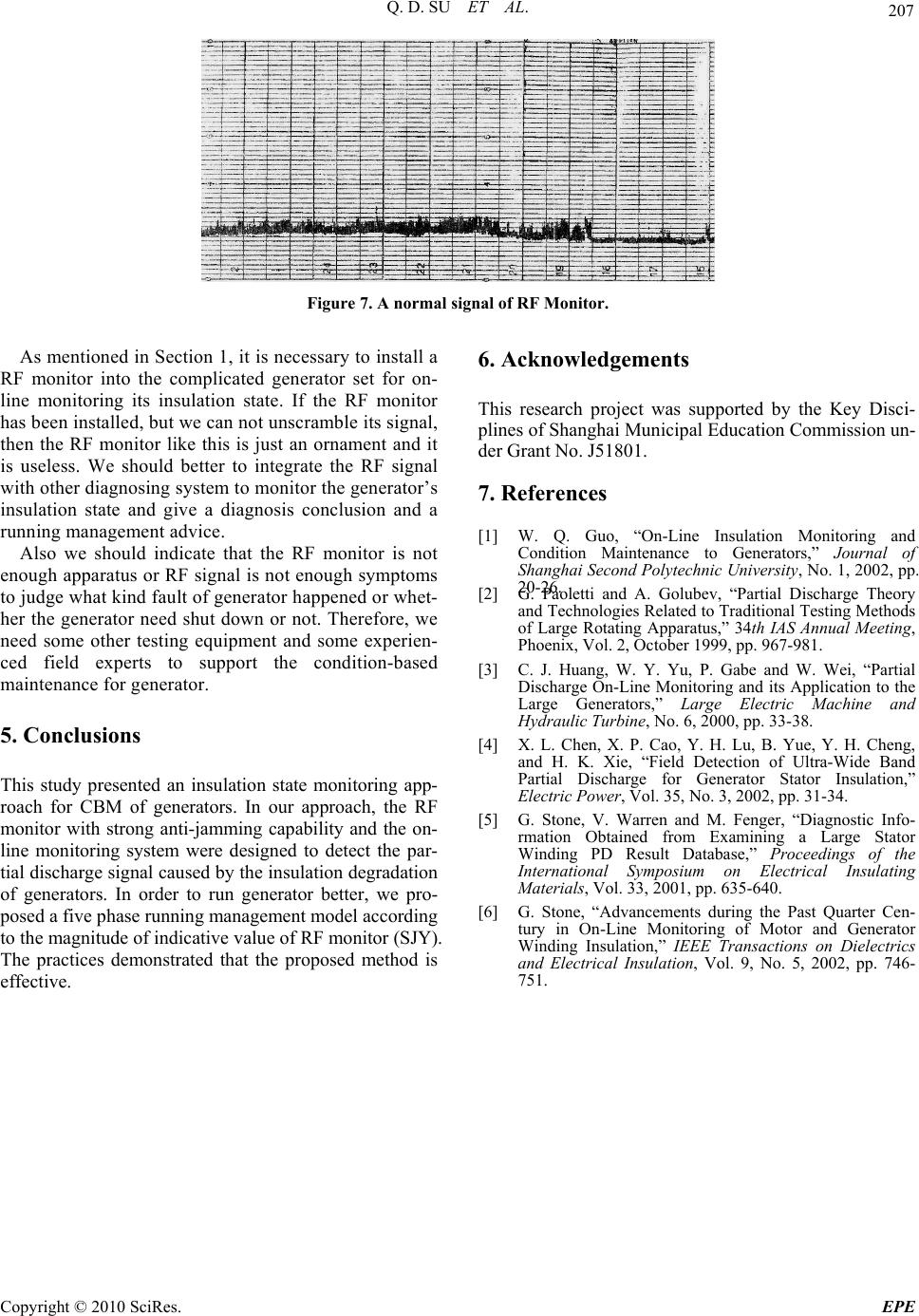 Q. D. SU ET AL. Copyright © 2010 SciRes. EPE 207 Figure 7. A normal signal of RF Monitor. As mentioned in Section 1, it is necessary to install a RF monitor into the complicated generator set for on- line monitoring its insulation state. If the RF monitor has been installed, but we can not unscramble its signal, then the RF monitor like this is just an ornament and it is useless. We should better to integrate the RF signal with other diagnosing system to monitor the generator’s insulation state and give a diagnosis conclusion and a running management advice. Also we should indicate that the RF monitor is not enough apparatus or RF signal is not enough symptoms to judge what kind fault of generator happened or whet- her the generator need shut down or not. Therefore, we need some other testing equipment and some experien- ced field experts to support the condition-based maintenance for generator. 5. Conclusions This study presented an insulation state monitoring app- roach for CBM of generators. In our approach, the RF monitor with strong anti-jamming capability and the on- line monitoring system were designed to detect the par- tial discharge signal caused by the insulation degradation of generators. In order to run generator better, we pro- posed a five phase running management model according to the magnitude of indicative value of RF monitor (SJY). The practices demonstrated that the proposed method is effective. 6. Acknowledgements This research project was supported by the Key Disci- plines of Shanghai Municipal Education Commission un- der Grant No. J51801. 7. References [1] W. Q. Guo, “On-Line Insulation Monitoring and Condition Maintenance to Generators,” Journal of Shanghai Second Polytechnic University, No. 1, 2002, pp. 20-26. [2] G. Paoletti and A. Golubev, “Partial Discharge Theory and Technologies Related to Traditional Testing Methods of Large Rotating Apparatus,” 34th IAS Annual Meeting, Phoenix, Vol. 2, October 1999, pp. 967-981. [3] C. J. Huang, W. Y. Yu, P. Gabe and W. Wei, “Partial Discharge On-Line Monitoring and its Application to the Large Generators,” Large Electric Machine and Hydraulic Turbine, No. 6, 2000, pp. 33-38. [4] X. L. Chen, X. P. Cao, Y. H. Lu, B. Yue, Y. H. Cheng, and H. K. Xie, “Field Detection of Ultra-Wide Band Partial Discharge for Generator Stator Insulation,” Electric Power, Vol. 35, No. 3, 2002, pp. 31-34. [5] G. Stone, V. Warren and M. Fenger, “Diagnostic Info- rmation Obtained from Examining a Large Stator Winding PD Result Database,” Proceedings of the International Symposium on Electrical Insulating Materials, Vol. 33, 2001, pp. 635-640. [6] G. Stone, “Advancements during the Past Quarter Cen- tury in On-Line Monitoring of Motor and Generator Winding Insulation,” IEEE Transactions on Dielectrics and Electrical Insulation, Vol. 9, No. 5, 2002, pp. 746- 751. |