Paper Menu >>
Journal Menu >>
 Materials Sciences and Applications, 2010, 1, 135-140 doi:10.4236/msa.2010.13022 Published Online August 2010 (http://www.SciRP.org/journal/msa) Copyright © 2010 SciRes. MSA 135 Effects of Fillerwire Composition along with Different Pre- and Post-Heat Treatment on Mechanical Properties of AISI 4130 Welded by the GTAW Process Ali Emamian1, Ardalan Emamian2, Amir Hossein Kowkabi3 1Department of Mechanical and Mechatronics Engineering, University of Waterloo, Waterloo, Canada; 2Department of Mechanical Engineering, IAU, Esfahan, Iran; 3Department of Material Science and Engineering, Sharif University of Technology, Tehran, Iran. Email: aemamian@engmail.uwaterloo.ca Received May 8th, 2010; revised May 31st, 2010; accepted June 8th, 2010. ABSTRACT This research intends to find out the optimal mechanical properties of AISI 4130 steel welded by the GTAW process. Six test plates were joined by two types of filler wire with similar chemical composition to the base metal, and with lower carbon content and slightly higher alloy elements content compared to the first one. Test plates then exerted three dif- ferent pre-heat and post-heat treatments on both groups. The three types of heat treatments were alternatively without pre-heat and post-heat, with pre-heat only, and finally with pre-heat and post-heat. Tensile, side bends and impact tests (for weld zone and HAZ) have been conducted. Results show that using low-carbon filler wire along with pre- and post-heat resulted in outstanding mechanical properties. Keywords: HAZ (Heat Affected Zone), Filler Wire, Pre- and Post-heat Treatments, GTAW Process 1. Introduction The unending search for novel mechanical properties has led to significant development in material with high str- ength. The 4130 grade of chrom-moly is in the HSLA group of steel. Although 4130 is not lighter than general steels, its higher specific strength ratio enables the engi- neers to reduce the weight of designs by using thinner thicknesses. Having ductility and specific strength at the same time increases the applications of 4130 in the aero- space, machinery, and motor sports industries. The sensitivity of high-strength and ultra-high-strength steel to the welding, increases the need to investigate the weld ability and mechanical properties of these types of steel. In the welding process the heat affected zone is he- ated above its critical temperature (A3 or Acm). On the other hand, the cooling rate of steel affects its microstr- ucture and constructs different phases. According to the chemical composition of AISI4130 (Table 1), due to its hardness and CCT diagram, it is probable to have ferritic- perlitic, ferritic-bainaitic or martensitic structure. Con- sequently, different microstructures result in different mechanical properties. During the welding process, mechanical properties of weld joints can drop dramatically [1,2]. Bevis and Fulcer et al. provide information about welding of 4130 tubes with thicknesses less than 1/8 inches. Todd et al. studied tube welding and technical issues of 4130 [3,4]. Earolino et al. studied the effect of carbon content and alloy ele- ments on maximizing the hardness of liquid boundaries [5]. They observed an increase in the hardness of weld metal and the liquid boundary. Changing the chemical composition by filler wire and dilution does not affect the HAZ in constant welding parameters. Therefore, the afore-mentioned studies do not provide sufficient infor- mation about HAZ properties. Kyte et al. and Hooijmians et al. have investigated hy- drogen cracking and hydrogen removal during GTAW welding. They developed a model which shows the relat- ion between hydrogen content and welding parameters [6,7]. Still et al. investigated the necessary conditions for cold cracking and the forming of bainite or martensite [8]. In the past decade, a considerable portion of the litera- ture has focused on technical aspects or advanced tech- nology devices such as laser or electron beam welding to  Effects of Fillerwire Composition Along with Different Pre- and Post-Heat Treatment 136 onMechanical Properties of AISI 4130 Welded by the GTAW Process study fatigue, crack growth or residual stress on 4130 [9]. Fatigue is a complex phenomenon compared to tensile, impact or bending properties. Without complete unders- tanding of a material’s behavior in tensile, impact or ben- ding tests, dynamic test results are difficult to interpret. Also using lasers or other advanced devices is not always an option in many cases due to their exorbitant cost. Ravi et al. have studied the effect of post weld heat tr- eatment on estimated fracture toughness. They assert that PWHT does not affect the impact toughness of weld met- al [10]. Marcelino et al. have studied the crack growth rate in weld metal, HAZ and base metal in repaired welded joi- nts. They discovered that the fastest fatigue crack growth was in weld metal [11]. Bultel et al. have investigated the effect of temperature on fatigue life considering the ph- ase transformation of ferritic-perlitic and bainitic in 4130 steel [12]. In the welding of 4130 steel, two important factors sh- ould be taken into the account: the chemical composition of the weld metal and heat-affected zone mechanical pro- perties. Throughout the literature, no detailed or satisfac- tory explanation was found regarding controlling weld and HAZ mechanical properties. This lack of data is due in part the majority of published papers being technical reports. Most of the published papers related to this res- earch field can be found in 1980-1997, where HSLA pro- perties generally, either in weld metal or in HAZ, are investigated [13-16]. However, there remains a profound lack of knowledge about the relationship between heat treatment/weld composition and the mechanical proper- ties of AISI 4130 welded parts. The purpose of this research is to define the optimal condition for welding of 4130 steel with the GTAW pro- cess by considering the chemistry of weld metal affected by filler wire and heat treatment simultaneously. 2. Experimental Method AISI 4130 plates sized at 400 × 200 × 10 mm were sele- cted to weld perpendicular to the rolling direction. To protect the weld pool and focus the weld spot in order to lessen the heat affected zone area, the GTAW process is selected. Next, a single Vee-Joint is made by the milling mach- ine at an angle of 30˚. The number of plates provided is twelve, which results in six test plates after being welded two by two. Three of the six test plates are welded by the filler wire B, whose analysis is like the base metal as pr- esented in Table 3. The remaining test plates are welded by a very low carbon filler wire L (Table 4). In both cases, the test plates are first welded without pre-/post-heat treatments (prefix 1). Next, the test plates are welded with pre-heat treatments (prefix 2). Finally, the test plates are welded with both pre- and post-heat treatments (prefix 3). In the case studies clarified above, all conditions and welding parameters such as amperage, voltage, argon gas flow (for protection) and welding sp- eed are controlled to be constant. The pre-heat treatment is done by a torch at about 200˚C. At this stage, the tem- perature is controlled by a thermometer. The inter-pass temperature in all samples is determined to be about 150-250˚C. In the post-heating treatment, the samples are placed in a furnace with temperature of about 200˚C, which slowly rises to 600˚C. The samples remain at this temperature inside the furnace for about an hour. They are then taken out of the furnace to cool to room temperature. Afterw- ards, a non-destructive testing process (ultrasonic and radiography) is applied to the samples in order to ensure that the weldments are sound and crack free. The test specimens are cut from the test plates according to AWS D1.1 and ASME SEC 9 standards. The test plates include two tensile, four side bending and six impact test speci- mens, of which three belong to the weld metal and three to the HAZ. The temperature of the impact tests is de- creased to –50˚C by alcohol and dry ice. 3. Results and Discussion Table 1 shows the coding system of samples. Micro hardness test results are illustrated in Table 5. Each res- ult is an average of at least five measurements at the same level of weld or heat affected zone. Only the pre and post-heated samples show uniform hardness results in the weld metal and HAZ. Table 1. Coding system Tensile test Hardness test Bending test Impact test ABD ABD ABD ABCD A can be L (stands for low carbon, high alloy filler metal) or B (stands for filler metal with same chemical composition as base metal) B can be 1 (stands for without pre-/post-heat treatment), 2 (stands for pre-heat be treatment) or 3 (stands for pre- and post-heat treatment samples) D is sample number C can W (stands for weld metal) or H (heat affected zone) Copyright © 2010 SciRes. MSA  Effects of Fillerwire Composition Along with Different Pre- and Post-Heat Treatment 137 onMechanical Properties of AISI 4130 Welded by the GTAW Process Table 6 shows that the ultimate tensile strength in both types of filler wires decreases when applying both pre- heat treatments and pre- and post-heat treatments. Pre- heat resulted in lower cooling rate and retard the forma- tion of brittle and hard phases in weld and HAZ. More- over, post weld heat treatment decreases the strength by tempering of formed brittle phases which are constructed during the welding process. Generally higher amounts of tensile testing can be observed in samples which are welded by filler metal with higher carbon content (B pre- fix compared to L). Samples were broken out of the weld and close to the fusion line; hence, a higher amount of carbon in the filler wire B is the main reason for elevated tensile results. Table 2. Chemical analysis of AISI4130 steel %C %Si %S %P %Mn %Ni %Cr 0.25 0.23 0.003 0.010 0.49 0.088 0.91 %Mo %Cu %Ti %Sn %V %Al 0.19 0.11 0.003 0.008 0.007 0.019 Table 3. Chemical analysis of high carbon filler wire (similar to base metal ) type B %C %Cr %Mo 0.3 0.8 0.24 Table 4. Chemical analysis of low carbon filler wire type L %C %Cr %Mo 0.04 1.1 0.58 Table 5. Hardness test results (HVN) Sample No. HAZ Weld Metal Base Metal B11 267 325 241 B21 260 338 245 B31 222 227 211 L11 270 274 259 L21 265 267 272 L31 220 271 248 Table 6. Tensile test results Sample No. % Elongation Ultimate Tensile Strength (N/MM2) As rolled 4130 23 766 As rolled 4130 17 773 B11 - 800 B12 - 793 B21 - 760 B22 - 753 B31 - 664 B32 - 653 L11 - 746 L12 - 762 L21 - 693 L22 - 687 L31 - 615 L32 - 660 Copyright © 2010 SciRes. MSA 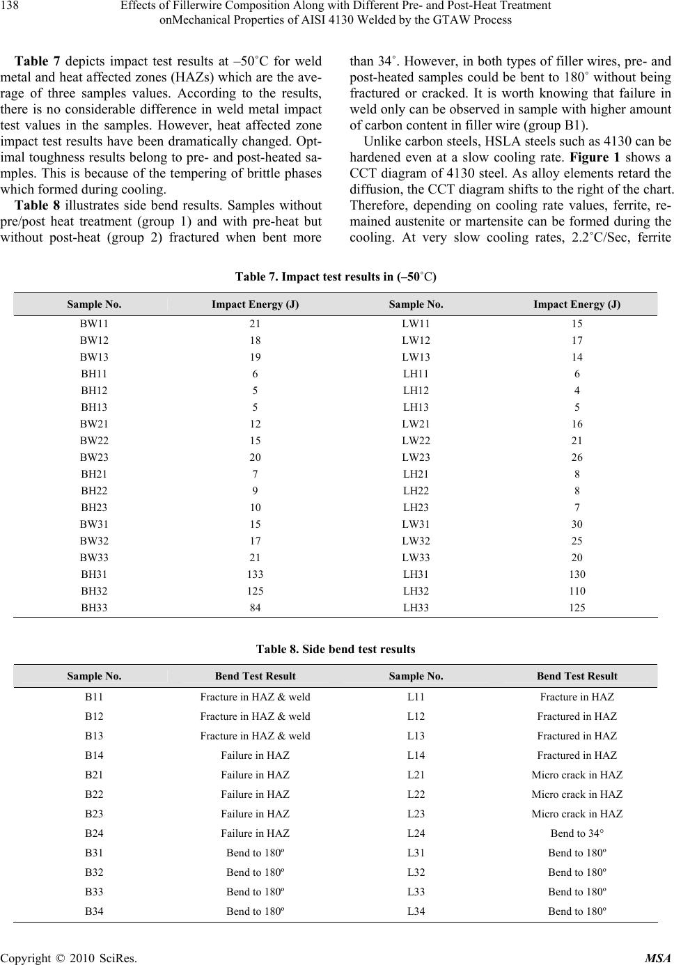 Effects of Fillerwire Composition Along with Different Pre- and Post-Heat Treatment 138 onMechanical Properties of AISI 4130 Welded by the GTAW Process Table 7 depicts impact test results at –50˚C for weld metal and heat affected zones (HAZs) which are the ave- rage of three samples values. According to the results, there is no considerable difference in weld metal impact test values in the samples. However, heat affected zone impact test results have been dramatically changed. Opt- imal toughness results belong to pre- and post-heated sa- mples. This is because of the tempering of brittle phases which formed during cooling. Table 8 illustrates side bend results. Samples without pre/post heat treatment (group 1) and with pre-heat but without post-heat (group 2) fractured when bent more than 34˚. However, in both types of filler wires, pre- and post-heated samples could be bent to 180˚ without being fractured or cracked. It is worth knowing that failure in weld only can be observed in sample with higher amount of carbon content in filler wire (group B1). Unlike carbon steels, HSLA steels such as 4130 can be hardened even at a slow cooling rate. Figure 1 shows a CCT diagram of 4130 steel. As alloy elements retard the diffusion, the CCT diagram shifts to the right of the chart. Therefore, depending on cooling rate values, ferrite, re- mained austenite or martensite can be formed during the cooling. At very slow cooling rates, 2.2˚C/Sec, ferrite Table 7. Impact test results in (–50˚C) Sample No. Impact Energy (J) Sample No. Impact Energy (J) BW11 21 LW11 15 BW12 18 LW12 17 BW13 19 LW13 14 BH11 6 LH11 6 BH12 5 LH12 4 BH13 5 LH13 5 BW21 12 LW21 16 BW22 15 LW22 21 BW23 20 LW23 26 BH21 7 LH21 8 BH22 9 LH22 8 BH23 10 LH23 7 BW31 15 LW31 30 BW32 17 LW32 25 BW33 21 LW33 20 BH31 133 LH31 130 BH32 125 LH32 110 BH33 84 LH33 125 Table 8. Side bend test results Sample No. Bend Test Result Sample No. Bend Test Result B11 Fracture in HAZ & weld L11 Fracture in HAZ B12 Fracture in HAZ & weld L12 Fractured in HAZ B13 Fracture in HAZ & weld L13 Fractured in HAZ B14 Failure in HAZ L14 Fractured in HAZ B21 Failure in HAZ L21 Micro crack in HAZ B22 Failure in HAZ L22 Micro crack in HAZ B23 Failure in HAZ L23 Micro crack in HAZ B24 Failure in HAZ L24 Bend to 34° B31 Bend to 180º L31 Bend to 180º B32 Bend to 180º L32 Bend to 180º B33 Bend to 180º L33 Bend to 180º B34 Bend to 180º L34 Bend to 180º Copyright © 2010 SciRes. MSA 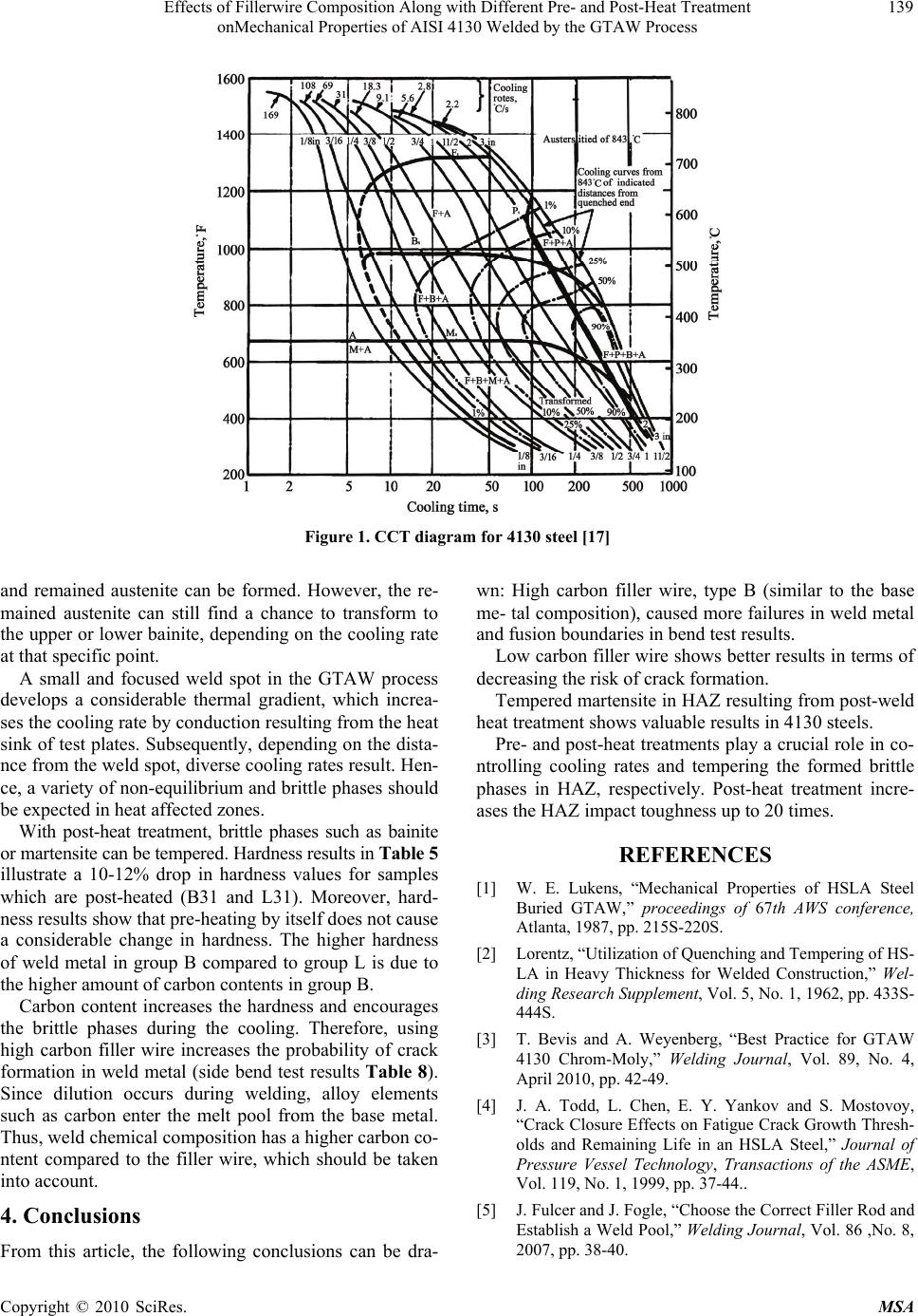 Effects of Fillerwire Composition Along with Different Pre- and Post-Heat Treatment 139 onMechanical Properties of AISI 4130 Welded by the GTAW Process Figure 1. CCT diagram for 4130 steel [17] and remained austenite can be formed. However, the re- mained austenite can still find a chance to transform to the upper or lower bainite, depending on the cooling rate at that specific point. A small and focused weld spot in the GTAW process develops a considerable thermal gradient, which increa- ses the cooling rate by conduction resulting from the heat sink of test plates. Subsequently, depending on the dista- nce from the weld spot, diverse cooling rates result. Hen- ce, a variety of non-equilibrium and brittle phases should be expected in heat affected zones. With post-heat treatment, brittle phases such as bainite or martensite can be tempered. Hardness results in Table 5 illustrate a 10-12% drop in hardness values for samples which are post-heated (B31 and L31). Moreover, hard- ness results show that pre-heating by itself does not cause a considerable change in hardness. The higher hardness of weld metal in group B compared to group L is due to the higher amount of carbon contents in group B. Carbon content increases the hardness and encourages the brittle phases during the cooling. Therefore, using high carbon filler wire increases the probability of crack formation in weld metal (side bend test results Table 8). Since dilution occurs during welding, alloy elements such as carbon enter the melt pool from the base metal. Thus, weld chemical composition has a higher carbon co- ntent compared to the filler wire, which should be taken into account. 4. Conclusions From this article, the following conclusions can be dra- wn: High carbon filler wire, type B (similar to the base me- tal composition), caused more failures in weld metal and fusion boundaries in bend test results. Low carbon filler wire shows better results in terms of decreasing the risk of crack formation. Tempered martensite in HAZ resulting from post-weld heat treatment shows valuable results in 4130 steels. Pre- and post-heat treatments play a crucial role in co- ntrolling cooling rates and tempering the formed brittle phases in HAZ, respectively. Post-heat treatment incre- ases the HAZ impact toughness up to 20 times. REFERENCES [1] W. E. Lukens, “Mechanical Properties of HSLA Steel Buried GTAW,” proceedings of 67th AWS conference, Atlanta, 1987, pp. 215S-220S. [2] Lorentz, “Utilization of Quenching and Tempering of HS- LA in Heavy Thickness for Welded Construction,” Wel- ding Research Supplement, Vol. 5, No. 1, 1962, pp. 433S- 444S. [3] T. Bevis and A. Weyenberg, “Best Practice for GTAW 4130 Chrom-Moly,” Welding Journal, Vol. 89, No. 4, April 2010, pp. 42-49. [4] J. A. Todd, L. Chen, E. Y. Yankov and S. Mostovoy, “Crack Closure Effects on Fatigue Crack Growth Thresh- olds and Remaining Life in an HSLA Steel,” Journal of Pressure Vessel Technology, Transactions of the ASME, Vol. 119, No. 1, 1999, pp. 37-44.. [5] J. Fulcer and J. Fogle, “Choose the Correct Filler Rod and Establish a Weld Pool,” Welding Journal, Vol. 86 ,No. 8, 2007, pp. 38-40. Copyright © 2010 SciRes. MSA  Effects of Fillerwire Composition Along with Different Pre- and Post-Heat Treatment 140 onMechanical Properties of AISI 4130 Welded by the GTAW Process [6] L. P. Earolino, “The Effect of Carbon Content on the Need to Post Weld Heat Treat Low Alloy Steel Casting,” Welding Research Supplement, Vol. 5, No. 1, 1986, pp. 41-46. [7] W. S. Kyte, “Post Weld Heat Treatment for Hydrogen Removal,” Welding Research Supplement, Vol. 2, No. 2, 1979, pp. 54S-58S. [8] J. W. Hooijmians, “A Model of Hydrogen Absorption du- ring GTA Welding,” Welding Research Supplement, Vol. 9, No. 5, 1997, pp. 264S-268S. [9] J. R. Still, “Welding of 4130, 4140, Steels for Drilling Sys- tems,” Welding Journal, Vol. 23, No. 2, 1997, pp. 37- 41. [10] L. W. Tsay, Y. M. Li, C. Chen and S. W. Cheng, “Me- chanical Properties and Fatigue Crack Growth Rate of Laser Welded,” Journal of Fatigue, Vol. 14, No. 4, 1992, pp. 239-247. [11] S. Ravi, V. Balasubramanian and N. Nemat, “Influence of Post Weld Heat Treatment on Fatigue Life Prediction of Strength Mismatched HSLA Steel Welds,” Journal of Fatigue, Vol. 27, No. 5, May 2005, pp. 547-553. [12] H. Bultel and J. Vogt, “Influence of Heat Treatment on Fatigue Behavior of 4130 AISI Steel,” Journal of Fatigue, Vol. 2, No. 1, 2010, pp. 917-924. [13] P. Macelino and H. Voorwald, “Considerations about the Welding Repair Effects on the Structural Integrity of an Airframe Critical to the Flight-Safety,” Journal of Fa- tigue, Vol. 2, No. 1, 2010, pp. 1895-1903. [14] O. M. Akselen, “Assessment and Predications of HAZ Tensile Properties of HSLA,” Welding Research Suppl- ement, Vol. 7, No. 3, 1989, pp. 362S-365S. [15] R. E. Monley, “Evaluation of Various Filler Wire Compo- sitions for GTA Welding of Low Alloy Steels,” Welding Research Supplement, Vol. 3, No. 2, 1980, pp. 12S-135S. [16] S. C. Ernst, “Weld Ability of High Strength Low Expa- nder Supper Alloy,” Welding Research Supplement, Vol. 7, No. 4, 1989, pp. 418S-424S. [17] T. V. Philip, “Steel Products,” ASM, New York, 1995, pp. 421-423. [18] Data Base of Steel Transformation Diagrams, 2009. Copyright © 2010 SciRes. MSA |