Paper Menu >>
Journal Menu >>
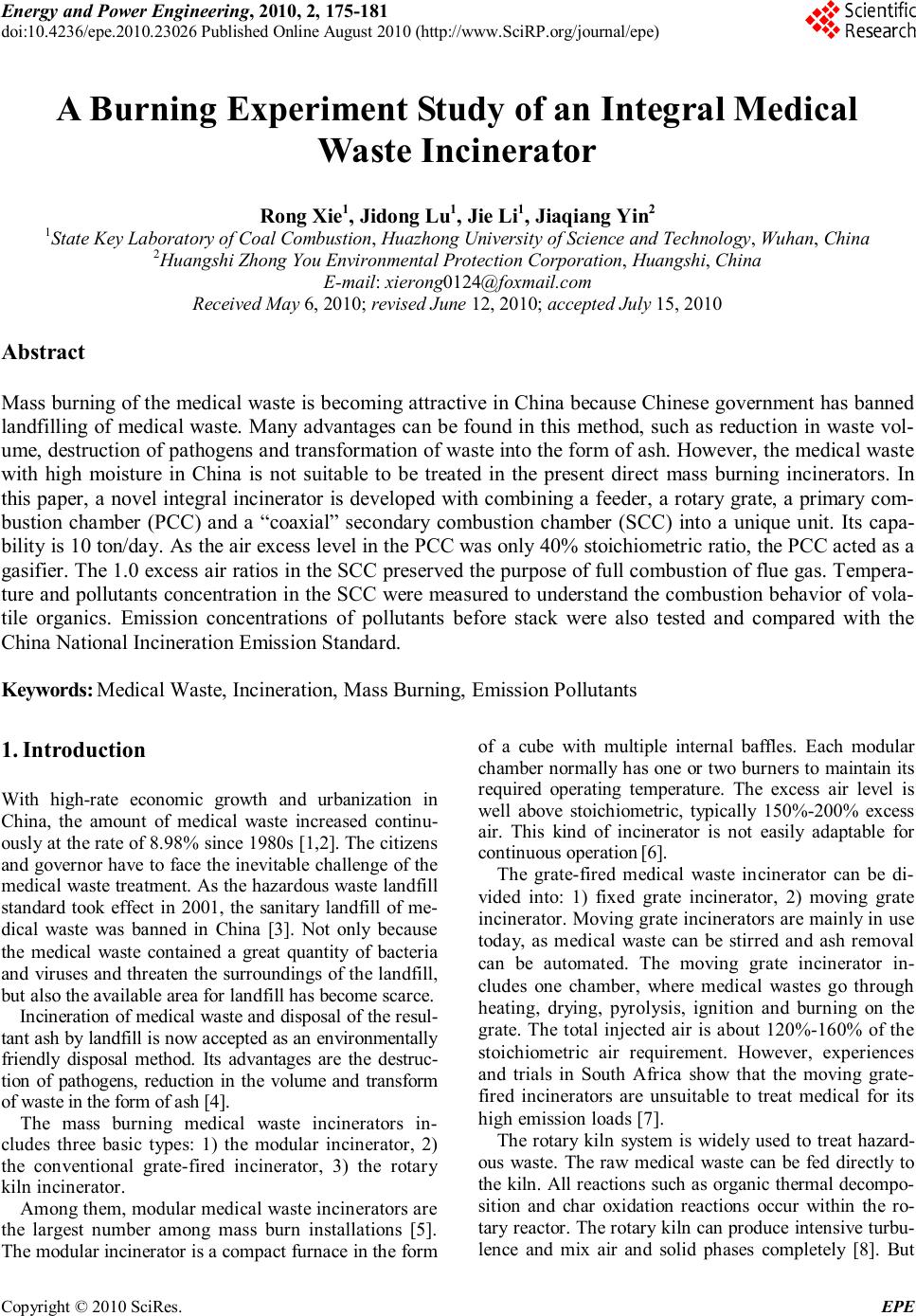 Energy and Power Engineering, 2010, 2, 175-181 doi:10.4236/epe.2010.23026 Published Online August 2010 (http://www.SciRP.org/journal/epe) Copyright © 2010 SciRes. EPE A Burning Experiment Study of an Integral Medical Waste Incinerator Rong Xie1, Jidong Lu1, Jie Li1, Jiaqiang Yin2 1State Key Laboratory of Coal Combustion, Huazhong University of Science and Technology, Wuhan, China 2Huangshi Zhong You Environmental Protection Corporation, Huangshi, China E-mail: xierong0124@foxmail.com Received May 6, 2010; revised June 12, 2010; accepted July 15, 2010 Abstract Mass burning of the medical waste is becoming attractive in China because Chinese government has banned landfilling of medical waste. Many advantages can be found in this method, such as reduction in waste vol- ume, destruction of pathogens and transformation of waste into the form of ash. However, the medical waste with high moisture in China is not suitable to be treated in the present direct mass burning incinerators. In this paper, a novel integral incinerator is developed with combining a feeder, a rotary grate, a primary com- bustion chamber (PCC) and a “coaxial” secondary combustion chamber (SCC) into a unique unit. Its capa- bility is 10 ton/day. As the air excess level in the PCC was only 40% stoichiometric ratio, the PCC acted as a gasifier. The 1.0 excess air ratios in the SCC preserved the purpose of full combustion of flue gas. Tempera- ture and pollutants concentration in the SCC were measured to understand the combustion behavior of vola- tile organics. Emission concentrations of pollutants before stack were also tested and compared with the China National Incineration Emission Standard. Keywords: Medical Waste, Incineration, Mass Burning, Emission Pollutants 1. Introduction With high-rate economic growth and urbanization in China, the amount of medical waste increased continu- ously at the rate of 8.98% since 1980s [1,2]. The citizens and governor have to face the inevitable challenge of the medical waste treatment. As the hazardous waste landfill standard took effect in 2001, the sanitary landfill of me- dical waste was banned in China [3]. Not only because the medical waste contained a great quantity of bacteria and viruses and threaten the surroundings of the landfill, but also the available area for landfill has become scarce. Incineration of medical waste and disposal of the resul- tant ash by landfill is now accepted as an environmentally friendly disposal method. Its advantages are the destruc- tion of pathogens, reduction in the volume and transform of waste in the form of ash [4]. The mass burning medical waste incinerators in- cludes three basic types: 1) the modular incinerator, 2) the conventional grate-fired incinerator, 3) the rotary kiln incinerator. Among them, modular medical waste incinerators are the largest number among mass burn installations [5]. The modular incinerator is a compact furnace in the form of a cube with multiple internal baffles. Each modular chamber normally has one or two burners to maintain its required operating temperature. The excess air level is well above stoichiometric, typically 150%-200% excess air. This kind of incinerator is not easily adaptable for continuous operation [6]. The grate-fired medical waste incinerator can be di- vided into: 1) fixed grate incinerator, 2) moving grate incinerator. Moving grate incinerators are mainly in use today, as medical waste can be stirred and ash removal can be automated. The moving grate incinerator in- cludes one chamber, where medical wastes go through heating, drying, pyrolysis, ignition and burning on the grate. The total injected air is about 120%-160% of the stoichiometric air requirement. However, experiences and trials in South Africa show that the moving grate- fired incinerators are unsuitable to treat medical for its high emission loads [7]. The rotary kiln system is widely used to treat hazard- ous waste. The raw medical waste can be fed directly to the kiln. All reactions such as organic thermal decompo- sition and char oxidation reactions occur within the ro- tary reactor. The rotary kiln can produce intensive turbu- lence and mix air and solid phases completely [8]. But  R. XIE ET AL. Copyright © 2010 SciRes. EPE 176 the high combustion efficiency is still depended on high auxiliary fuel consumption. Gas sealing of kiln and fixed parts is also a difficult problem. The three types of incinerators mentioned above pre- sented good performance in the mass burning of solid waste with high heat value (more than 2000 kcal/kg). However, in China little experience is available of these incinerators to treat medical waste of high moisture. In this paper, an integral medical waste incinerator is developed from the following consideration: 1) Achieve flue gas emission limits. 2) Reduce heat loss of the incin- erator. 3) Make full use of medical waste’s heat value. The integral medical waste incinerator combines a feeder, a rotary grate, a primary chamber and a “coaxial” secondary combustion chamber into a unique unit. The incineration feeding system continuously feeds medical waste into the incinerator. Heating, drying, pyrolysis of medical waste and char oxidation occur in the primary chamber, while gas phase oxidation reactions occur in the secondary chamber. As there is no similar structure of incinerator to our knowledge, the objective of this study are to introduce its novelty, investigate its performance and measure the combustion pollutants. 2. Incinerator System Description The diagrammatic sketch of incineration system and waste treatment process is shown in Figure 1. The basic com- ponents in the incineration system are the waste feed system, the combustion system and the air quality control system. The ash disposal and heat recovery are taken as a supplemental process. The details are described as fol- lowing. 2.1. Feeding System The special bin storing medical waste is weighed and loaded by the automatic crane, which charges waste into a 2-meter high chute (C in Figure 2). Two steel clap- boards are installed in the chute to maintain good seal (B and E in Figure 2). So the chute can not only prevent air flowing into the primary chamber, but also prevent fire from the combustion chamber entering the feeding sys- tem. A reciprocating propeller (D in Figure 2) installed in the chute feeds the waste into the primary combustion chamber. 2.2. Primary Combustion Chamber The primary combustion chamber (PCC) consists of a 1.2-meter diameter cylinder and a rotary grate. The grate is installed at the bottom of the PCC. The rotary grate is made up of three discs fixed on the central bearing body and one cone fixed on the top disc. Medical waste, pyro- lysates and bottom ashes are tumbled slowly with the rotation of the grate. Many small holes (5-cm diameter) Figure 1. Schematic diagram of incineration system.  R. XIE ET AL. Copyright © 2010 SciRes. EPE 177 A. charge hopper B. first access slide board C. vertical bin D. reciprocating propeller E. secondary access slide board F. combustion chamber Figure 2. Schematic diagram of the feeding system. distribute symmetrically on each disc. So the holes with the space between discs can distribute air homogene- ously. In the PCC, The raw medical waste is distributed unif- ormly onto the waste bed by the feeding system and forms about 1.5 meters waste bed on the surface of the rotary grate. Continuous feeding and slagging make the waste bed maintained at a fixed height. The raw medical waste undergoes heating and drying process on the the waste bed as soon as the raw medical waste enters. This process removes the moisture in the raw medical waste. When the temperature of medical waste rises up to a level, the pyrolysis and volatilization of the solid medical waste start. After pyrolysis and volatilization process, the remained solid char is further oxidized and forms hot slag. The air for the solid char combustion is drawn from the bottom entrance of the PCC at the room temperature by a forced draft fan. The “cold” air runs through the hot slag layer on the surface of the rotary grate. So the air is heated up while the hot slag is cooled down. The cooled slag forms a protective layer on the surface of the rotary grate, which isolates the grate from the high temperature combustion region. The grate is free from heat transfigu- ration during the combustion process. The heated air is then transferred into the combustion area-solid carbon oxidation layer. The char can be oxi- dized completely under full excess air and produce lots of hot flue gases. These hot flue gases pass through the pyrolysis layer and upwards into the heating and drying layer. The heat in the hot gases can supply enough en- ergy for pyrolysis and drying process of the raw medical waste. 2.3. Secondary Combustion Chamber The secondary combustion chamber (SCC) has a distinct cylinder configuration. We call it “coaxial” structure, as it surrounds the PCC with the same vertical axis. This design significantly decreases the PCC and the SCC outer jacket’s contact area with the environment. No pipeline is needed for connection between the PCC and the SCC, so the heat loss in pipeline occurring in tradi- tional multi-chamber incinerator is eliminated. The baf- fles are installed in the SCC to guide the combustion gases through 180˚ turn in vertical directions. This “U” shape combustion channels can significant increase gas turbu- lence in the high temperature region. In case of the same volume of the combustion chamber, the length of flue gas channel is increased relatively, so the residence time of flue gas at temperatures exceeding 800℃ is ensured for at least 2 seconds. Secondary air is preheated by a heat ex- changer and supplied at the top of the secondary combus- tion chamber. The secondary air injector is fixed in tan- gential direction to achieve well mixed effect. Manipulation of combustion in the SCC includes ‘3Ts’ combustion control (temperature, time and turbulence) in order to maximize system efficiency and minimize envi- ronmental adverse effect of the incineration. If the com- bustion temperature is below 800℃ the ignition equip- ment will start automatically and auxiliary fuel is in- jected to maintain the temperature. In fact the fuel injec- tion is necessary when the mass burning starts. When combustion is stable, the heat release from oxidation reactions can keep temperature exceeding 800℃. 2.4. Flue Gas Purification System After incineration, the flue gases pass through the pipe and enters the into the flue gas purification system. In order to prevent the erosion by acidic flue gas and flush- ing by the entrained particles, a thin layer of silicon car- bide is coated on the surfaced of the pipe. The flue gas is then induced into semidry scrubbing system. Lime slurry is injected by a spry nozzle in the scrubber. It has high and stable removal efficiency for HCl and SOX. No waste- water treatment equipment is required. After that, flue gas goes through the demister tower. Activated carbon is injected into the flue gas to absorb the dioxins and furans formed in the post combustion process before it enters the baghouse. Finally the purified flue gases are induced into the stack by diversion fun. 3. Medical Waste Incineration Experiments and Results 3.1. Waste Characteristics The typical medical waste was sampled from the same batch by random sampling method. First typical medical waste sample was sterilization by high temperature steam. Secondly, the large pieces of hard objects removed from  R. XIE ET AL. Copyright © 2010 SciRes. EPE 178 the sample. Finally sample was grinded for proximate analysis and then dried for ultimate and energy analysis. The ultimate analysis of typical medical waste is show in Table 1. The ultimate analysis of a waste component typically involves the determination of the percent of carbon (C), hydrogen (H), oxygen (O), nitrogen (N) and sulfur(S). Table 1 gives the average chemical composi- tion of combustible component of medical waste. The energy content of the medical waste is determined by a laboratory bomb calorimeter. Typical energy content of medical waste is also estimated and showed in Table 1. 3.2. Air Supply The air supply in the PCC is only about 40% of the stoi- chiometric requirement, equal to 1/3-1/4 of the recom- mended air levels (140-200%) for traditional mass burn system [9]. In the lower part of the PCC, this air is en- sured to burn out the solid char. However, in the upper zone, the PCC is acting as a gasifier. Pyrolysis is the dominant mechanism in this zone for the production of volatiles from medical waste in the absence of oxygen. The produced volatiles have been identified as CO, CO2, H2O, CH4 and other light hydrocarbons. The air supply in the SCC is 100% of the stoichiomet- ric requirement for complete waste combustion, so the volatiles from PCC can be decomposed completely. 3.3. Incineration Temperature Armored thermocouples were installed in PCC and SCC outlet as measurement equipment of temperature. The detection accuracy of the thermocouples is 1℃. Varia- tion of temperature with time in the PCC and SCC is shown in Figure 3. The temperature of PCC is around 640℃. However the value varied significantly with time. Because materials of medical waste range from food products to pathological waste, there is large variation in the properties of medical wastes. These variations have a dramatic impact on the performance of medical waste incinerator. Although the combustion and pyrolysis mechanisms in PCC are complex, it is demonstrated that the pyrolysis production of volatiles and char can be regulated by tem- perature [10]. The decomposition of the organic matter is normally total at these high temperatures. When the py- rolysis temperature is much lower, the production of CO is much decreased. The low temperature may slow down the pyrolysis process and lead to delay the time of raw waste ignition. When the pyrolysis temperature is much higher, the self-combustion process became unstable. Because high temperature present in the PCC may lead to excessive burning of the pyrolysate. It will decrease the quantity of combustive pyrolysate in the SCC. Con- sequently the auxiliary fuel has to be consumed to main- tain the temperature in the SCC. After several testing before operation, the optimal running temperature for the PCC was set at 660℃. It can be found in Figure 3 that the actual operating temperature is close to the setting temperature. The combustion temperature in the SCC is higher than 850℃, and the temperature varied slightly with time ex- cept the heavy disturbing effect from the PCC. This in- dicates combustion process in SCC is more stable than the process in PCC. The novel coaxial chamber design decreases 40% outer contact area of the SCC with the environment. Heat losses are much reduced. It is easy for SCC to achieve high temperature and remain stable op- eration. 3.4. Pollutants and Oxygen in the SCC In actual operation, whether volatiles are combusted com- pletely in the SCC is an important performance indicator of the incinerator. Gas pollutants at different positions of the SCC were tested by portable infrared flue gas ana- lyzer. Several verification tests of the gas analyzer were carried out before the experiment to avoid measurement errors. As illustrated in Figure 4, five sample points (la- beled as 1-5) were set symmetrically along the axial di- rection. Point “1” is near the PCC exit and point “5” is near the SCC outlet. In the stable operation conditions, each sample point is tested for three times. Table 1. Medical waste component. Proximate analysis (wt.%) Mar Vd Ad LHV (MJ/kg) 64.1 75.3 23.4 25.63 Ultimate analysis (wt.%) C H N S O 47.54 7.99 2.02 0.5 18.54 Figure 3. Variation of temperature in the PCC and the SCC.  R. XIE ET AL. Copyright © 2010 SciRes. EPE 179 Concentration profiles of pollutants (CO, CO2, NOX, and SO2) and oxygen are shown in Figure 5 to Figure 9. It can be seen from Figure 5 that the CO concentration decreases intensely from sample point “1” to “5”. This indicates that CO formed in the PCC is mostly destroyed in the SCC. The destruction efficiency of CO is round 99.95%. It can be found from Figure 5 that CO2 is mainly formed in the SCC. The comparison between Figure 5 and Figure 6 can further explain that CO Inlet 1 2 3 4 5 Outlet Figure 4. Sampling points distribution in the SCC. Figure 5. CO concentration. Figure 6. CO2 concentration. mostly translated into CO2 in the SCC. As is illustrated in Figure 7, concentration of oxygen is gradually decre- ased with the oxidation reaction going-on. Generally speaking, the concentration of oxygen in the SCC outlet is higher than 10%, which meets the demand of Medical Waste Incineration Standard [11]. From Figure 8 and Figure 9, we can find that concentration of NOX and SO2 are lower than 30 ppm and 10 ppm, respectively. These may be due to medical waste containing little N and S elements. However NOX and SO2 mainly formed in the pyrolysis process decrease little in the SCC. Conclusions can be made that combustion in the SCC has no effect on production of NOX and SO2. 3.5. Pollutant Concentrations in the Stack Concentrations of NOX, SOX, HCl and particles in the Figure 7. O2 concentration. Figure 8. SO2 concentration.  R. XIE ET AL. Copyright © 2010 SciRes. EPE 180 Figure 9. NOX concentration. exhaust were measured respectively according to the Ch- ina National Standards [11]. Concentration of CO, CO2, O2 were also measured by a Combustion Efficiency Mea- surement Instrument. The maximum air pollutant concentrations in the inlet of the stack are summarized in Table 2. National Incin- eration Emission Standard for each component is also listed in the Table 2. As shown in Table 2, the measured pollutants belong generally to the concentration range set by China National Standards. As Table 2 shows, the experimental value of particulates in the stack is much lower than the limit. In addition to the well operated bag- filter, the low air level in the PCC is an important reason. Compared with the traditional mass burning system, star- ved-air combustion in the PCC produces less solid parti- cles in the gas stream. Researchers have demonstrated that the dioxin formation from carbon particulates is one of the potential mechanisms for PCDD/F formation in the post combustion zone [12,13]. The reduced fly ash entrainment in flue gas is helpful to control the dioxins. The concentration of acid gases such as HCl and SO2 are also lower than the limit. This demonstrates that gas scrubber is in good working condition. 4. Conclusions The integral medical waste incinerator combines a feeder, a rotary grate, a primary chamber and a “coaxial” secon- dary combustion chamber into a unique unit. The tempe- rature of the PCC varied significantly with time because of the intermittent feed and the heterogeneous character- istics of the raw medical waste, however, due to the co- axial SCC design, the combustion temperature in the SCC varied slightly with time. The temperature has great effect during the formation of pyrolysis gas such as CO. The low air level (40%) in the PCC well controlled the Table 2. Emission concentration of pollutants in the flue gas. Pollutants Experimental values Standard CO, mg/m3 34.8 80 NOX, mg/m3 15.1 400 SO2, mg/m3 24.2 260 HCl, mg/m3 48.7 75 O2, mg/m3 16.3 6-11 Particulates, mg/m3 32 80 Blackness 0.8 1 chamber’s temperature. The actual operating temperature in the PCC (640℃) is close to the setting temperature (660℃). Consequently, char combustion is also kept sta- ble and complete. Concentrations of pollutants in the SCC were measured on different sample points. In these data, CO level represented the best available estimate of environmentally satisfactory operation for the incinerat- ion process. The destruction efficiency of total CO in the SCC is round 99.95%. Emission concentrations of pollu- tants in the stack were also measured and met the de- mand of the China National Incineration Emission Stan- dard. 5. References [1] R. Xie, W. J. Li, J. Li, et al. , “Emissions Investigation for A Novel Medical Waste Incinerator,” Journal of Haz- ardous Materials, Vol. 166, No. 1, 2009, pp. 365-371. [2] J. M. Zhu, H. M. Zhu, X. G. Jiang, et al., “Analysis of Volatile Species Kinetics during Typical Medical Waste Pyrolysis Using A Distributed Activation Energy Model,” Journal of Hazardous Materials, Vol. 162, No. 2-3, 2009, pp. 646-651. [3] State Environmental Protection Administration of China, “Standard for Pollution Control on the Security Landfill for Hazardous Wastes,” National Technical Standard of China (GB 18598-2001). [4] W. R. Niessen, “Combustion and Incineration Processes,” 3rd Edition, Marcel Dekker Inc, New York, 2002. [5] C. C. Lee and G. L. Huffman, “Medical Waste Manage- ment Incineration,” Journal of Hazardous Materials, Vol. 48, No. 1-3, 1996, pp. 1-30. [6] A. F. Shaaban, “Process Engineering Design of Patho- logical Waste Incinerator with an Integrated Combustion Gases Treatment Unit, ” Journal of Hazardous Materials, Vol. 145, No. 1-2, 2007, pp. 195-202. [7] D. E. Rogers and A. C. Brent, “Small-Scale Medical Waste Incinerators Experiences and Trials in South Af- rica,” Waste Management, Vol. 26, No. 11, 2006, pp. 1229-1236. [8] G. R. Woodle and J. M. Munro, “Particle Motion and Mixing in A Rotary Kiln,” Power Technology, Vol. 76,  R. XIE ET AL. Copyright © 2010 SciRes. EPE 181 No. 3, 1993, pp. 187-190. [9] A. R. Lawrence, “Energy from Municipal Solid Waste: A Comparison with Coal Combustion Technology,” Pro- gress in Energy and Combustion Science, Vol. 24, No. 6, 1998, pp. 545-564. [10] H. M. Zhu, J. H. Yan and X. G. Jiang, “Study on Pyroly- sis of Typical Medical Waste Materials by Using TG- FTIR Analysis,” Journal of Hazardous Materials, Vol. 153, No. 1-2, 2008, pp. 670-676. [11] State Council of China, “Decree of the Medical Waste Management,” Chinese Environmental Science Press, Bei- jing, 2003. [12] L. Stieglitz and H. Vogg, “On Formation Conditions of PCDD/F in Flyash from Municipal Waste Incinerators,” Chemosphere, Vol. 16, No. 8-9, 1987, pp. 1917-1922. [13] B. K. Gullet, K. R. Bruce, L. O. Beach, et al., “Mechanis- tic Steps in the Production of PCCD and PCDF during Waste Combustion,” Chemosphere, Vol. 25, No. 7-10, 1992, pp. 1387-1392. |