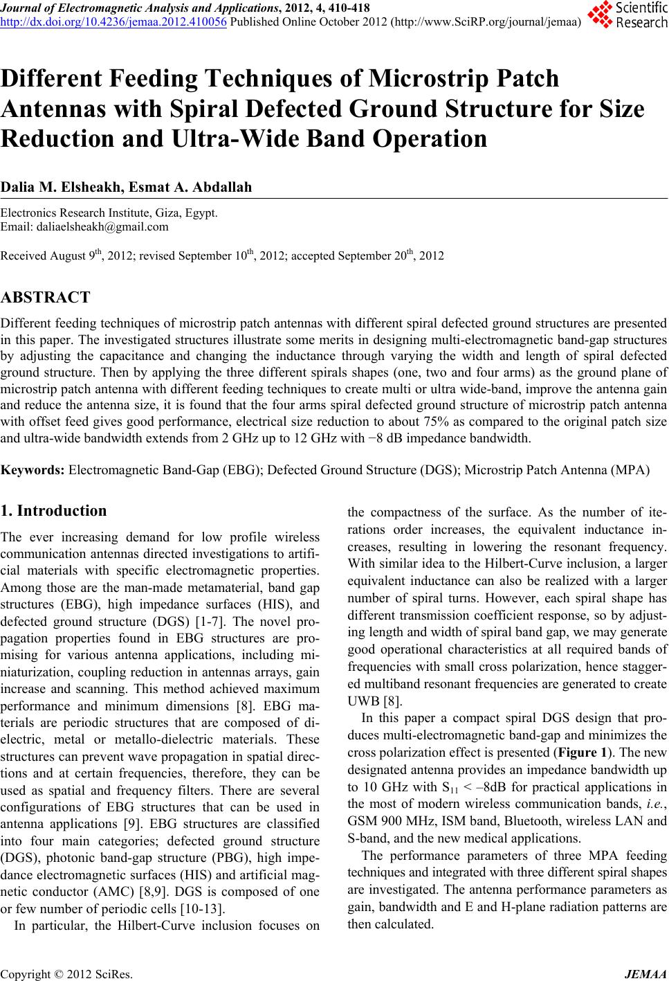
 Journal of Electromagnetic Analysis and Applications, 2012, 4, 410-418 http://dx.doi.org/10.4236/jemaa.2012.410056 Published Online October 2012 (http://www.SciRP.org/journal/jemaa) 1 Different Feeding Techniques of Microstrip Patch Antennas with Spiral Defected Ground Structure for Size Reduction and Ultra-Wide Band Operation Dalia M. Elsheakh, Esmat A. Abdallah Electronics Research Institute, Giza, Egypt. Email: daliaelsheakh@gmail.com Received August 9th, 2012; revised September 10th, 2012; accepted September 20th, 2012 ABSTRACT Different feeding techniques of microstrip patch antennas with different spiral defected ground structures are presented in this paper. The investigated structures illustrate some merits in designing multi-electromagnetic band-gap structures by adjusting the capacitance and changing the inductance through varying the width and length of spiral defected ground structure. Then by applying the three different spirals shapes (one, two and four arms) as the ground plane of microstrip patch antenna with different feeding techniques to create multi or ultra wide-band, improve the antenna gain and reduce the antenna size, it is found that the four arms spiral defected ground structure of microstrip patch antenna with offset feed gives good performance, electrical size reduction to about 75% as compared to the original patch size and ultra-wide bandwidth extends from 2 GHz up to 12 GHz with −8 dB impedance bandwidth. Keywords: Electromagnetic Band-Gap (EBG); Defected Ground Structure (DGS); Microstrip Patch Antenna (MPA) 1. Introduction The ever increasing demand for low profile wireless communication antennas directed investigations to artifi- cial materials with specific electromagnetic properties. Among those are the man-made metamaterial, band gap structures (EBG), high impedance surfaces (HIS), and defected ground structure (DGS) [1-7]. The novel pro- pagation properties found in EBG structures are pro- mising for various antenna applications, including mi- niaturization, coupling reduction in antennas arrays, gain increase and scanning. This method achieved maximum performance and minimum dimensions [8]. EBG ma- terials are periodic structures that are composed of di- electric, metal or metallo-dielectric materials. These structures can prevent wave propagation in spatial direc- tions and at certain frequencies, therefore, they can be used as spatial and frequency filters. There are several configurations of EBG structures that can be used in antenna applications [9]. EBG structures are classified into four main categories; defected ground structure (DGS), photonic band-gap structure (PBG), high impe- dance electromagnetic surfaces (HIS) and artificial mag- netic conductor (AMC) [8,9]. DGS is composed of one or few number of periodic cells [10-13]. In particular, the Hilbert-Curve inclusion focuses on the compactness of the surface. As the number of ite- rations order increases, the equivalent inductance in- creases, resulting in lowering the resonant frequency. With similar idea to the Hilbert-Curve inclusion, a larger equivalent inductance can also be realized with a larger number of spiral turns. However, each spiral shape has different transmission coefficient response, so by adjust- ing length and width of spiral band gap, we may generate good operational characteristics at all required bands of frequencies with small cross polarization, hence stagger- ed multiband resonant frequencies are generated to create UWB [8]. In this paper a compact spiral DGS design that pro- duces multi-electromagnetic band-gap and minimizes the cross polarization effect is presented (Figure 1). The new designated antenna provides an impedance bandwidth up to 10 GHz with S11 < –8dB for practical applications in the most of modern wireless communication bands, i.e., GSM 900 MHz, ISM band, Bluetooth, wireless LAN and S-band, and the new medical applications. The performance parameters of three MPA feeding techniques and integrated with three different spiral shapes are investigated. The antenna performance parameters as gain, bandwidth and E and H-plane radiation patterns are then calculated. Copyright © 2012 SciRes. JEMAA 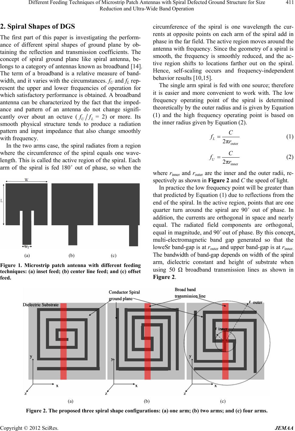 Different Feeding Techniques of Microstrip Patch Antennas with Spiral Defected Ground Structure for Size Reduction and Ultra-Wide Band Operation 411 2. Spiral Shapes of DGS The first part of this paper is investigating the perform- ance of different spiral shapes of ground plane by ob- taining the reflection and transmission coefficients. The concept of spiral ground plane like spiral antenna, be- longs to a category of antennas known as broadband [14]. The term of a broadband is a relative measure of band- width, and it varies with the circumstances. fU and fL rep- resent the upper and lower frequencies of operation for which satisfactory performance is obtained. A broadband antenna can be characterized by the fact that the imped- ance and pattern of an antenna do not change signifi- cantly over about an octave (UL f= 2) or more. Its smooth physical structure tends to produce a radiation pattern and input impedance that also change smoothly with frequency. In the two arms case, the spiral radiates from a region where the circumference of the spiral equals one wave- length. This is called the active region of the spiral. Each arm of the spiral is fed 180˚ out of phase, so when the (a) (b) (c) Figure 1. Microstrip patch antenna with different feeding techniques: (a) inset feed; (b) center line feed; and (c) offset feed. circumference of the spiral is one wavelength the cur- rents at opposite points on each arm of the spiral add in phase in the far field. The active region moves around the antenna with frequency. Since the geometry of a spiral is smooth, the frequency is smoothly reduced, and the ac- tive region shifts to locations farther out on the spiral. Hence, self-scaling occurs and frequency-independent behavior results [10,15]. The single arm spiral is fed with one source; therefore it is easier and more convenient to work with. The low frequency operating point of the spiral is determined theoretically by the outer radius and is given by Equation (1) and the high frequency operating point is based on the inner radius given by Equation (2). outer 2π L C fr (1) inner 2π U C fr (2) where rinner and router are the inner and the outer radii, re- spectively as shown in Figure 2 and C the speed of light. In practice the low frequency point will be greater than that predicted by Equation (1) due to reflections from the end of the spiral. In the active region, points that are one quarter turn around the spiral are 90˚ out of phase. In addition, the currents are orthogonal in space and nearly equal. The radiated field components are orthogonal, equal in magnitude, and 90˚ out of phase. By this concept, multi-electromagnetic band gap generated so that the loweSr band-gap is at router and upper band-gap is at rinner. The bandwidth of band-gap depends on width of the spiral arm, dielectric constant and height of substrate when using 50 Ω broadband transmission lines as shown in Figure 2. (a) (b) (c) Figure 2. The proposed three spiral shape configurations: (a) one arm; (b) two arms; and (c) four arms. Copyright © 2012 SciRes. JEMAA 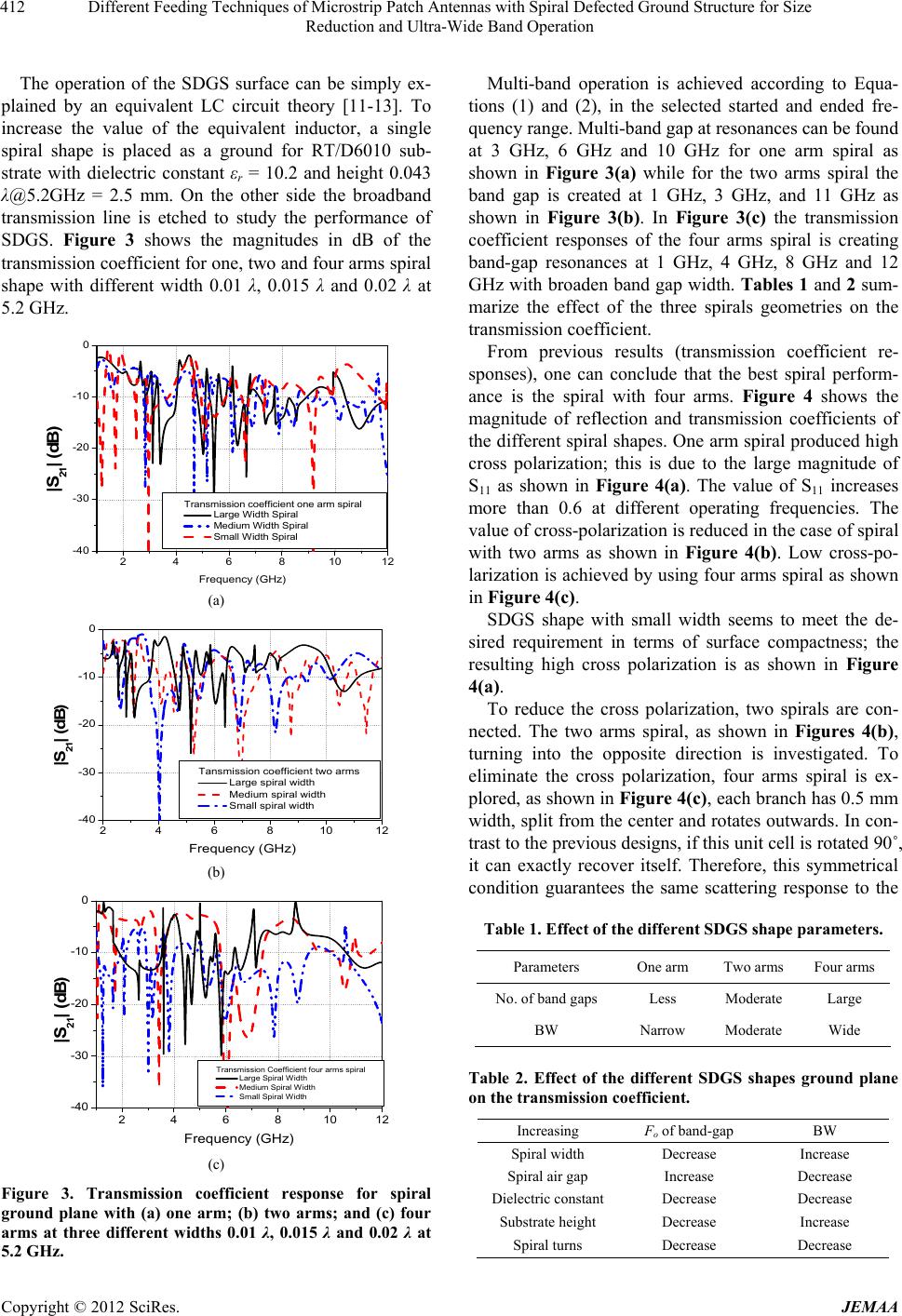 Different Feeding Techniques of Microstrip Patch Antennas with Spiral Defected Ground Structure for Size Reduction and Ultra-Wide Band Operation 412 The operation of the SDGS surface can be simply ex- plained by an equivalent LC circuit theory [11-13]. To increase the value of the equivalent inductor, a single spiral shape is placed as a ground for RT/D6010 sub- strate with dielectric constant εr = 10.2 and height 0.043 λ@5.2GHz = 2.5 mm. On the other side the broadband transmission line is etched to study the performance of SDGS. Figure 3 shows the magnitudes in dB of the transmission coefficient for one, two and four arms spiral shape with different width 0.01 λ, 0.015 λ and 0.02 λ at 5.2 GHz. 246810 12 -40 -30 -20 -10 0 |S 21 | (d B) Frequency (G Hz) Transmission coefficient one arm spiral Large Width Spiral Medium Width Spiral Small Width Spiral (a) 2468101 -40 -30 -20 -10 0 |S 21 | (d B) Frequency (GHz) Tansmission coefficient two arms Large spiral width Medium spiral width Small spiral width (b) 246810 12 -40 -30 -20 -10 0 |S 21 | (d B) Frequency (GHz) Transmission Coefficient four arms spiral Large Spiral Width Medium Spiral Width Small Spiral Width (c) Figure 3. Transmission coefficient response for spiral ground plane with (a) one arm; (b) two arms; and (c) four arms at three different widths 0.01 λ, 0.015 λ and 0.02 λ at 5.2 GHz. Multi-band operation is achieved according to Equa- tions (1) and (2), in the selected started and ended fre- quency range. Multi-band gap at resonances can be found at 3 GHz, 6 GHz and 10 GHz for one arm spiral as shown in Figure 3(a) while for the two arms spiral the band gap is created at 1 GHz, 3 GHz, and 11 GHz as shown in Figure 3(b). In Figure 3(c) the transmission coefficient responses of the four arms spiral is creating band-gap resonances at 1 GHz, 4 GHz, 8 GHz and 12 GHz with broaden band gap width. Table s 1 and 2 sum- marize the effect of the three spirals geometries on the transmission coefficient. From previous results (transmission coefficient re- sponses), one can conclude that the best spiral perform- ance is the spiral with four arms. Figure 4 shows the magnitude of reflection and transmission coefficients of the different spiral shapes. One arm spiral produced high cross polarization; this is due to the large magnitude of S11 as shown in Figure 4(a). The value of S11 increases more than 0.6 at different operating frequencies. The value of cross-polarization is reduced in the case of spiral with two arms as shown in Figure 4(b). Low cross-po- larization is achieved by using four arms spiral as shown in Figure 4(c). SDGS shape with small width seems to meet the de- sired requirement in terms of surface compactness; the resulting high cross polarization is as shown in Figure 4(a). To reduce the cross polarization, two spirals are con- nected. The two arms spiral, as shown in Figures 4(b), turning into the opposite direction is investigated. To eliminate the cross polarization, four arms spiral is ex- plored, as shown in Figure 4(c), each branch has 0.5 mm width, split from the center and rotates outwards. In con- trast to the previous designs, if this unit cell is rotated 90˚, it can exactly recover itself. Therefore, this symmetrical condition guarantees the same scattering response to the Table 1. Effect of the different SDGS shape parameters. Parameters One arm Two arms Four arms No. of band gaps Less Moderate Large BW Narrow Moderate Wide Table 2. Effect of the different SDGS shapes ground plane on the transmission coefficient. Increasing Fo of band-gap BW Spiral width Decrease Increase Spiral air gap Increase Decrease Dielectric constantDecrease Decrease Substrate height Decrease Increase Spiral turns Decrease Decrease Copyright © 2012 SciRes. JEMAA 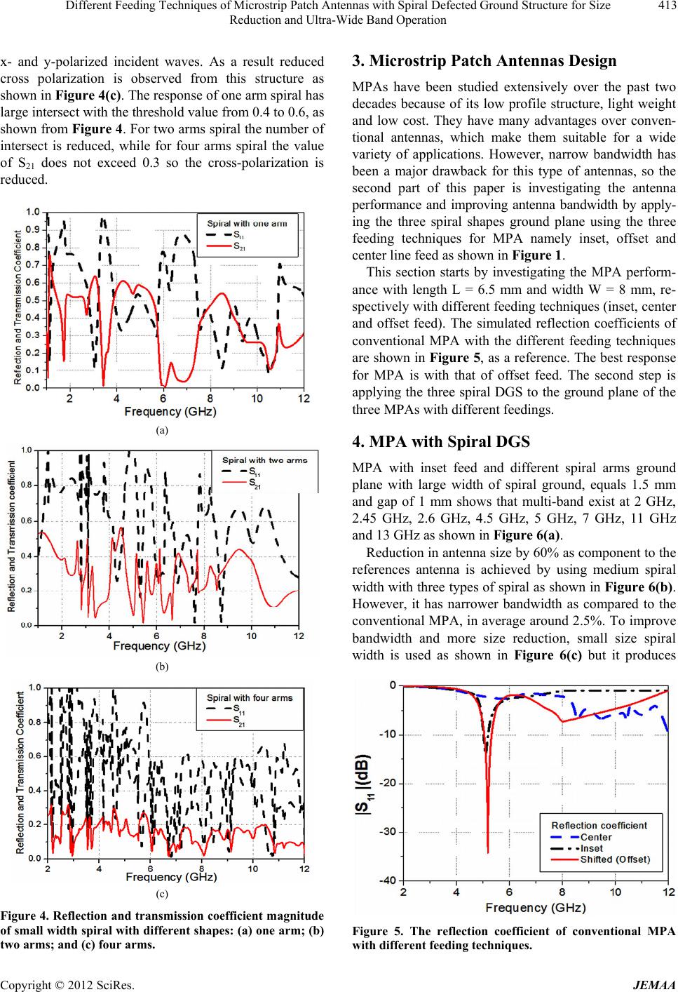 Different Feeding Techniques of Microstrip Patch Antennas with Spiral Defected Ground Structure for Size Reduction and Ultra-Wide Band Operation 413 x- and y-polarized incident waves. As a result reduced cross polarization is observed from this structure as shown in Figure 4(c). The response of one arm spiral has large intersect with the threshold value from 0.4 to 0.6, as shown from Figure 4. For two arms spiral the number of intersect is reduced, while for four arms spiral the value of S21 does not exceed 0.3 so the cross-polarization is reduced. (a) (b) (c) Figure 4. Reflection and transmission coefficient magnitude of small width spiral with different shapes: (a) one arm; (b) two arms; and (c) four arms. 3. Microstrip Patch Antennas Design MPAs have been studied extensively over the past two decades because of its low profile structure, light weight and low cost. They have many advantages over conven- tional antennas, which make them suitable for a wide variety of applications. However, narrow bandwidth has been a major drawback for this type of antennas, so the second part of this paper is investigating the antenna performance and improving antenna bandwidth by apply- ing the three spiral shapes ground plane using the three feeding techniques for MPA namely inset, offset and center line feed as shown in Figure 1. This section starts by investigating the MPA perform- ance with length L = 6.5 mm and width W = 8 mm, re- spectively with different feeding techniques (inset, center and offset feed). The simulated reflection coefficients of conventional MPA with the different feeding techniques are shown in Figure 5, as a reference. The best response for MPA is with that of offset feed. The second step is applying the three spiral DGS to the ground plane of the three MPAs with different feedings. 4. MPA with Spiral DGS MPA with inset feed and different spiral arms ground plane with large width of spiral ground, equals 1.5 mm and gap of 1 mm shows that multi-band exist at 2 GHz, 2.45 GHz, 2.6 GHz, 4.5 GHz, 5 GHz, 7 GHz, 11 GHz and 13 GHz as shown in Figure 6(a). Reduction in antenna size by 60% as component to the references antenna is achieved by using medium spiral width with three types of spiral as shown in Figure 6(b). However, it has narrower bandwidth as compared to the conventional MPA, in average around 2.5%. To improve bandwidth and more size reduction, small size spiral width is used as shown in Figure 6(c) but it produces Figure 5. The reflection coefficient of conventional MPA with different feeding techniques. Copyright © 2012 SciRes. JEMAA 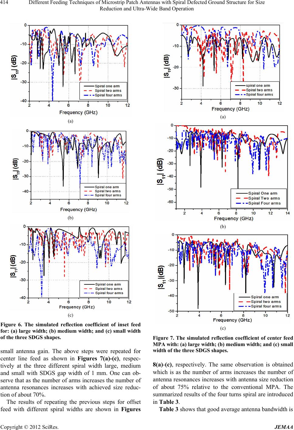 Different Feeding Techniques of Microstrip Patch Antennas with Spiral Defected Ground Structure for Size Reduction and Ultra-Wide Band Operation 414 (a) (b) (c) Figure 6. The simulated reflection coefficient of inset feed for: (a) large width; (b) medium width; and (c) small width of the three SDGS shapes. small antenna gain. The above steps were repeated for center line feed as shown in Figures 7(a)-(c), respec- tively at the three different spiral width large, medium and small with SDGS gap width of 1 mm. One can ob- serve that as the number of arms increases the number of antenna resonances increases with achieved size reduc- tion of about 70%. The results of repeating the previous steps for offset feed with different spiral widths are shown in Figures (a) (b) (c) Figure 7. The simulated reflection coefficient of center feed MPA with: (a) large width; (b) medium width; and (c) small width of the three SDGS shapes. 8(a)-(c), respectively. The same observation is obtained which is as the number of arms increases the number of antenna resonances increases with antenna size reduction of about 75% relative to the conventional MPA. The summarized results of the four turns spiral are introduced in Table 3. Table 3 shows that good average antenna bandwidth is Copyright © 2012 SciRes. JEMAA 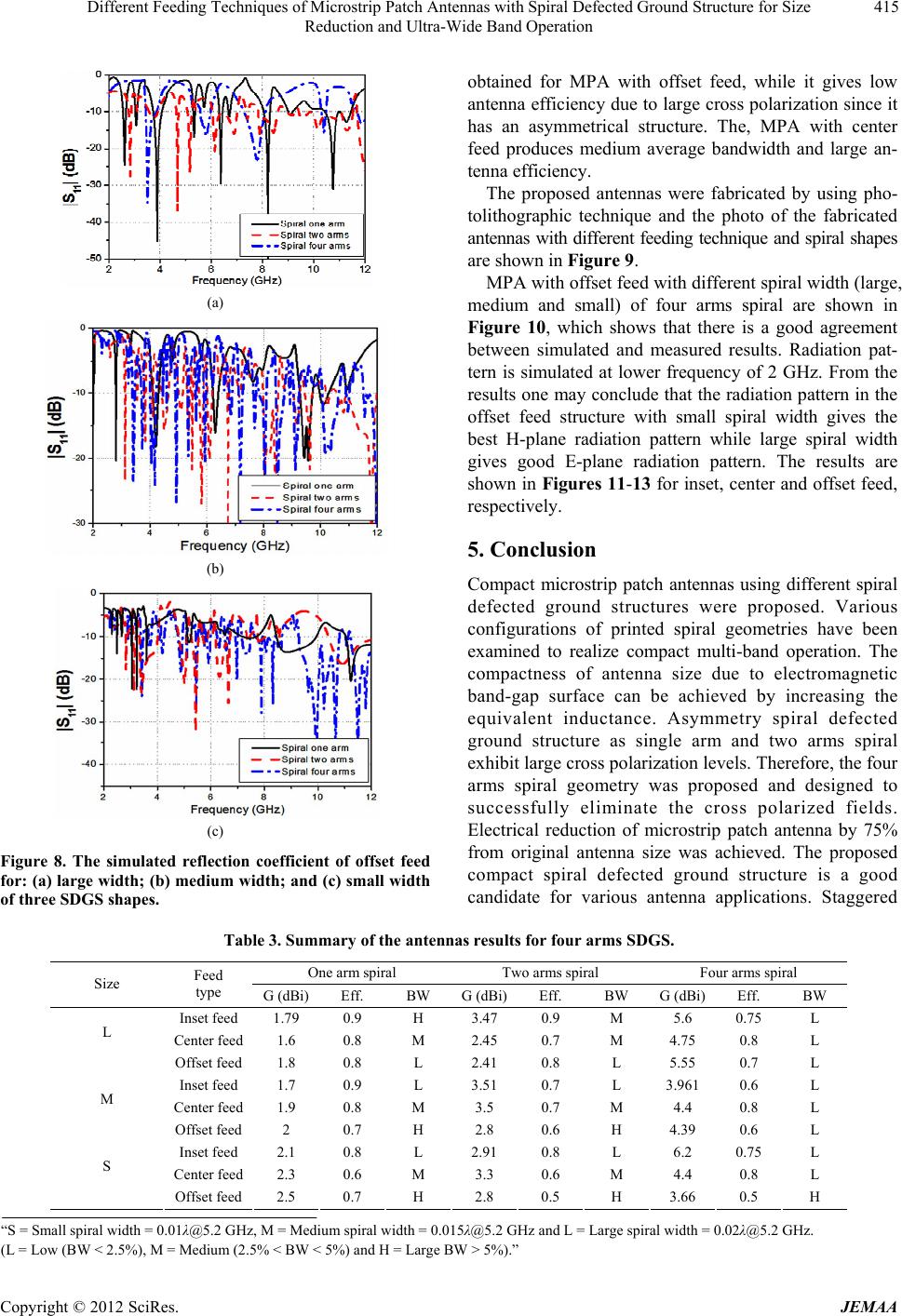 Different Feeding Techniques of Microstrip Patch Antennas with Spiral Defected Ground Structure for Size Reduction and Ultra-Wide Band Operation Copyright © 2012 SciRes. JEMAA 415 obtained for MPA with offset feed, while it gives low antenna efficiency due to large cross polarization since it has an asymmetrical structure. The, MPA with center feed produces medium average bandwidth and large an- tenna efficiency. The proposed antennas were fabricated by using pho- tolithographic technique and the photo of the fabricated antennas with different feeding technique and spiral shapes are shown in Figure 9. MPA with offset feed with different spiral width (large, medium and small) of four arms spiral are shown in Figure 10, which shows that there is a good agreement between simulated and measured results. Radiation pat- tern is simulated at lower frequency of 2 GHz. From the results one may conclude that the radiation pattern in the offset feed structure with small spiral width gives the best H-plane radiation pattern while large spiral width gives good E-plane radiation pattern. The results are shown in Figures 11-13 for inset, center and offset feed, respectively. (a) 5. Conclusion (b) Compact microstrip patch antennas using different spiral defected ground structures were proposed. Various configurations of printed spiral geometries have been examined to realize compact multi-band operation. The compactness of antenna size due to electromagnetic band-gap surface can be achieved by increasing the equivalent inductance. Asymmetry spiral defected ground structure as single arm and two arms spiral exhibit large cross polarization levels. Therefore, the four arms spiral geometry was proposed and designed to successfully eliminate the cross polarized fields. Electrical reduction of microstrip patch antenna by 75% from original antenna size was achieved. The proposed compact spiral defected ground structure is a good candidate for various antenna applications. Staggered (c) Figure 8. The simulated reflection coefficient of offset feed for: (a) large width; (b) medium width; and (c) small width of three SDGS shapes. Table 3. Summary of the antennas results for four arms SDGS. One arm spiral Two arms spiral Four arms spiral Size Feed type G (dBi) Eff. BW G (dBi)Eff. BW G (dBi) Eff. BW Inset feed 1.79 0.9 H 3.47 0.9 M 5.6 0.75 L Center feed 1.6 0.8 M 2.45 0.7 M 4.75 0.8 L L Offset feed 1.8 0.8 L 2.41 0.8 L 5.55 0.7 L Inset feed 1.7 0.9 L 3.51 0.7 L 3.961 0.6 L Center feed 1.9 0.8 M 3.5 0.7 M 4.4 0.8 L M Offset feed 2 0.7 H 2.8 0.6 H 4.39 0.6 L Inset feed 2.1 0.8 L 2.91 0.8 L 6.2 0.75 L Center feed 2.3 0.6 M 3.3 0.6 M 4.4 0.8 L S Offset feed 2.5 0.7 H 2.8 0.5 H 3.66 0.5 H “S = Small spiral width = 0.01λ@5.2 GHz, M = Medium spiral width = 0.015λ@5.2 GHz and L = Large spiral width = 0.02λ@5.2 GHz. (L = Low (BW < 2.5%), M = Medium (2.5% < BW < 5%) and H = Large BW > 5%).” 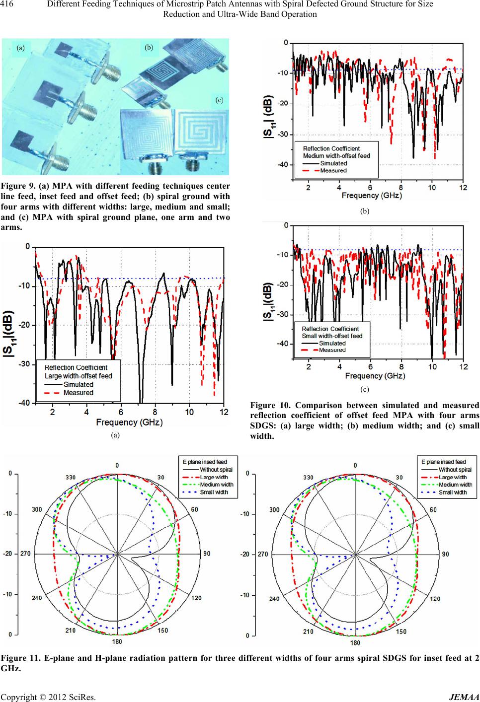 Different Feeding Techniques of Microstrip Patch Antennas with Spiral Defected Ground Structure for Size Reduction and Ultra-Wide Band Operation 416 Figure 9. (a) MPA with different feeding techniques center line feed, inset feed and offset feed; (b) spiral ground with four arms with different widths: large, medium and small; and (c) MPA with spiral ground plane, one arm and two arms. (a) (b) (c) Figure 10. Comparison between simulated and measured reflection coefficient of offset feed MPA with four arms SDGS: (a) large width; (b) medium width; and (c) small width. Figure 11. E-plane and H-plane radiation pattern for three different widths of four arms spiral SDGS for inset feed at 2 GHz. Copyright © 2012 SciRes. JEMAA 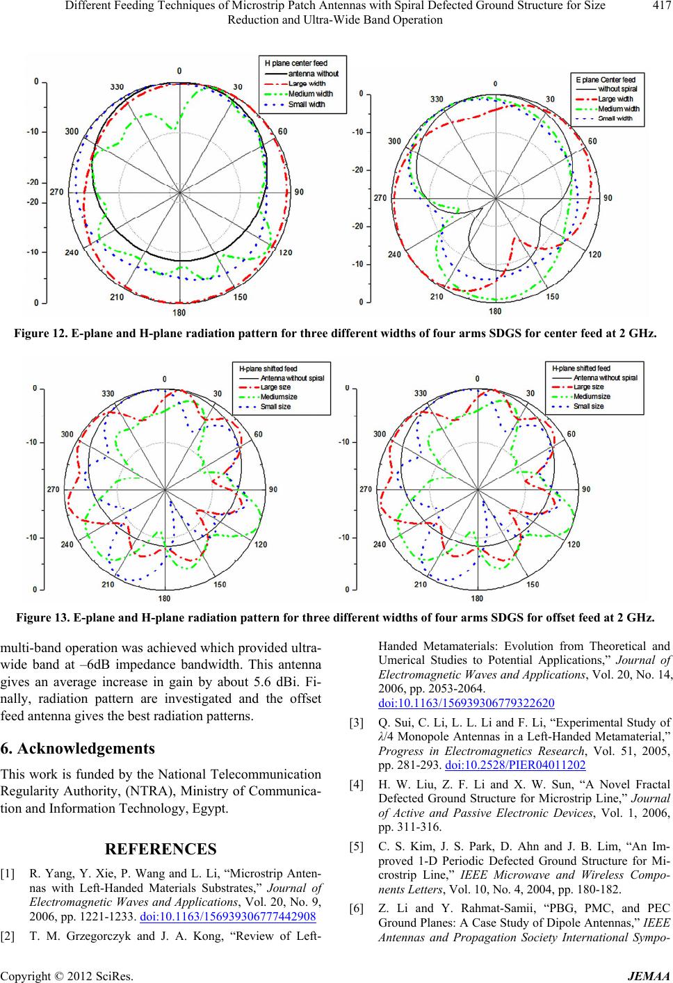 Different Feeding Techniques of Microstrip Patch Antennas with Spiral Defected Ground Structure for Size Reduction and Ultra-Wide Band Operation 417 Figure 12. E-plane and H-plane radiation pattern for three different widths of four arms SDGS for center feed at 2 GHz. Figure 13. E-plane and H-plane radiation pattern for three different widths of four arms SDGS for offset feed at 2 GHz. multi-band operation was achieved which provided ultra- wide band at –6dB impedance bandwidth. This antenna gives an average increase in gain by about 5.6 dBi. Fi- nally, radiation pattern are investigated and the offset feed antenna gives the best radiation patterns. 6. Acknowledgements This work is funded by the National Telecommunication Regularity Authority, (NTRA), Ministry of Communica- tion and Information Technology, Egypt. REFERENCES [1] R. Yang, Y. Xie, P. Wang and L. Li, “Microstrip Anten- nas with Left-Handed Materials Substrates,” Journal of Electromagnetic Waves and Applications, Vol. 20, No. 9, 2006, pp. 1221-1233. doi:10.1163/156939306777442908 [2] T. M. Grzegorczyk and J. A. Kong, “Review of Left- Handed Metamaterials: Evolution from Theoretical and Umerical Studies to Potential Applications,” Journal of Electromagnetic Waves and Applications, Vol. 20, No. 14, 2006, pp. 2053-2064. doi:10.1163/156939306779322620 [3] Q. Sui, C. Li, L. L. Li and F. Li, “Experimental Study of λ/4 Monopole Antennas in a Left-Handed Metamaterial,” Progress in Electromagnetics Research, Vol. 51, 2005, pp. 281-293. doi:10.2528/PIER04011202 [4] H. W. Liu, Z. F. Li and X. W. Sun, “A Novel Fractal Defected Ground Structure for Microstrip Line,” Journal of Active and Passive Electronic Devices, Vol. 1, 2006, pp. 311-316. [5] C. S. Kim, J. S. Park, D. Ahn and J. B. Lim, “An Im- proved 1-D Periodic Defected Ground Structure for Mi- crostrip Line,” IEEE Microwave and Wireless Compo- nents Letters, Vol. 10, No. 4, 2004, pp. 180-182. [6] Z. Li and Y. Rahmat-Samii, “PBG, PMC, and PEC Ground Planes: A Case Study of Dipole Antennas,” IEEE Antennas and Propagation Society International Sympo- Copyright © 2012 SciRes. JEMAA  Different Feeding Techniques of Microstrip Patch Antennas with Spiral Defected Ground Structure for Size Reduction and Ultra-Wide Band Operation 418 sium, Vol. 2, 2000, pp. 674-677. [7] C. S. Kim, J. S. Park, D. Ahn and J. B. Lim, “A Novel 1-D Periodic Defected Ground Structure for Planar Cir- cuits,” IEEE Microwave and Guided Wave Letters, Vol. 10, No. 4, 2000, pp. 131-133. doi:10.1109/75.846922 [8] D. Nashaat, H. A. Elsadek, E. Abdallah, H. Elhenawy and M. F. Iskander, “Ultra-Wide Bandwidth 2 × 2 Microstrip Patch Array Antenna by Using Electromagnetic Band- Gap Structure (EBG),” IEEE Transactions on Antenns Propagat, Vol. 59, No. 5, 2011, pp. 1528-1538. doi:10.1109/TAP.2011.2123052 [9] F. Yang and Y. S. Rahmat, “Electromagnetic Band Gap Structures in Antenna Engineering,” Press Cambridge, New York, 2008. [10] J. S. Lim, C. S. Kim, Y.-T. Lee, D. Ahn and S. Nam, “A Spiral Shaped Defected Ground Structure for Coplanar Waveguide,” IEEE Microwave and Wireless Components Letters, Vol. 12, No. 9, 2002, pp. 300-332. [11] D. Nashaat, H. A. Elsadek, E. Abdallah, H. Elhenawy and M. F. Iskander, “Electromagnetic Analyses and an Equi- valent Circuit Model of Microstrip Patch Antenna with Rectangular Defected Ground Plane,” IEEE Proceedings of Antennas and Propagation Society International Sym- posium, Charleston, 1-5 June 2009, pp. 1-4. [12] D. Nashaat, H. A. Elsadek, E. Abdallah, H. Elhenawy and M. F. Iskander, “Miniaturized and Multiband Operations of Inset Feed Microstrip Patch Antenna by Using Novel Shape of Defected Ground Structure (DGS) in Wireless Applications,” IEEE Antennas and Propagation Society International Symposium, Charleston, 1-5 June 2009, pp. 1-4. [13] D. Nashaat, H. A. Elsadek, E. Abdallah, H. Elhenawy and M. F. Iskander, “Reconfigurable Single and Multiband Inset Feed Microstrip Patch Antenna for Wireless Com- munication Devices,” Progress in Electromagnetics Re- search C, Vol. 12, 2010, pp. 191-201. doi:10.2528/PIERC10011503 [14] Y. Kim, F. Yang and A. Z. Elsherbeni, “Compact Artifi- cial Magnetic Conductor Design Planar Square Spiral Geometries,” Progress in Electromagnetics Research, Vol. 77, 2007, pp. 43-54. doi:10.2528/PIER07072302 [15] N. H. K. Hitosugi, N. Tatsuzawa, D. Togashi, H. Mimaki and J. Yamauchi, “Effects on the Radiation Characteris- tics of Using a Corrugated Reflector with a Helical An- tenna and an Electromagnetic Band-Gap Reflector with a Spiral Antenna,” IEEE Transactions on Antennas and Propagation, Vol. 53, No. 1, 2005, pp. 191-199. Copyright © 2012 SciRes. JEMAA
|