Journal of Minerals and Materials Characterization and Engineering, 2012, 11, 1027-1033
Published Online October 2012 (http://www.SciRP.org/journal/jmmce)
Study on Effect of Welding Speed on Micro Structure and
Mechanical Properties of Pulsed Current Micro Plasma
Arc Welded Inconel 625 Sheets
Chalamalasetti Srinivasa Rao1, Kondapalli Siva Prasad2*, Damera Nageswara Rao3
1Department of Mechanical Engineering, AU College of Engineering, Andhra University, Visakhapatnam, India
2Department of Mechanical Engineering, Anil Neerukonda Institute of Technology & Sciences, Visakhapatnam, India
3Vice Chancellor, Centurion University of Technology & Management, Odisha, India
Email: *kspanits@gmail.com
Received June 8, 2012; revised July 15, 2012; accepted July 30, 2012
ABSTRACT
Nickel alloys had gathered wide acceptance in the fabrication of components which require high temperature resistance
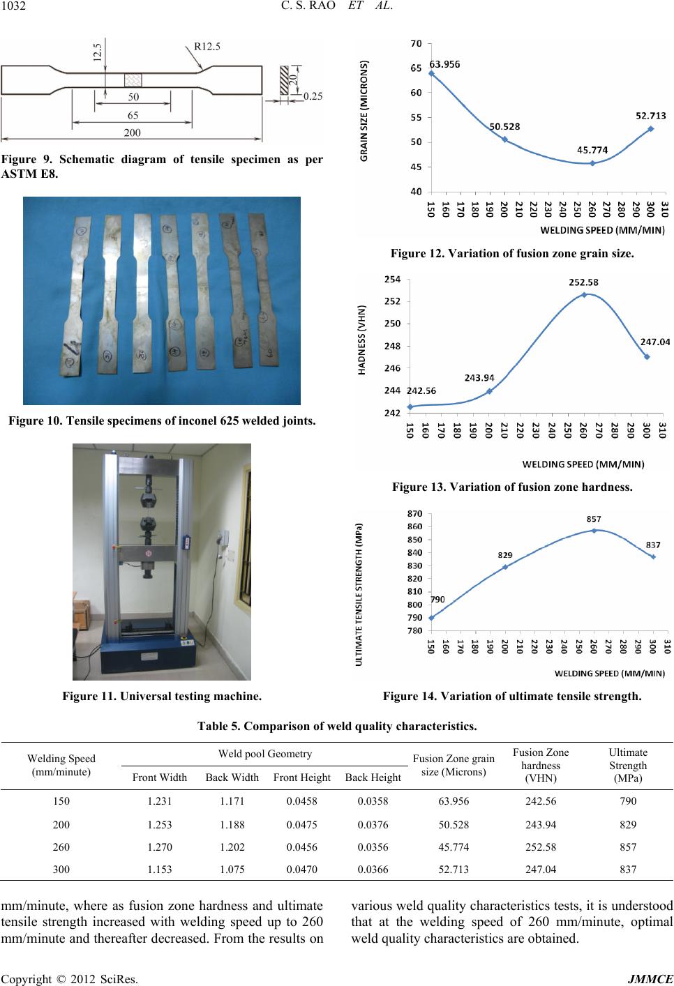
and corrosion resistance, such as metallic bellows used in expansion joints used in aircraft, aerospace and petroleum
industry. Micro Plasma Arc Welding (MPAW) is one of the important arc welding processes commonly using in fabric-
cation of Nickel alloys. In the present paper welding of Inconel 625 sheets using pulsed current micro plasma arc weld-
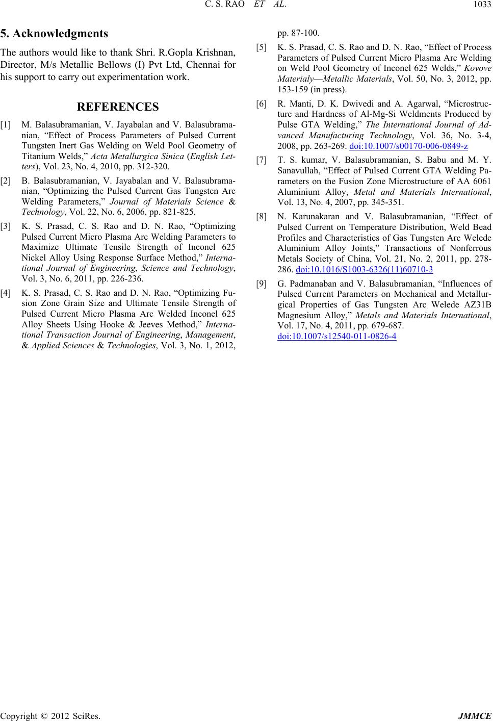
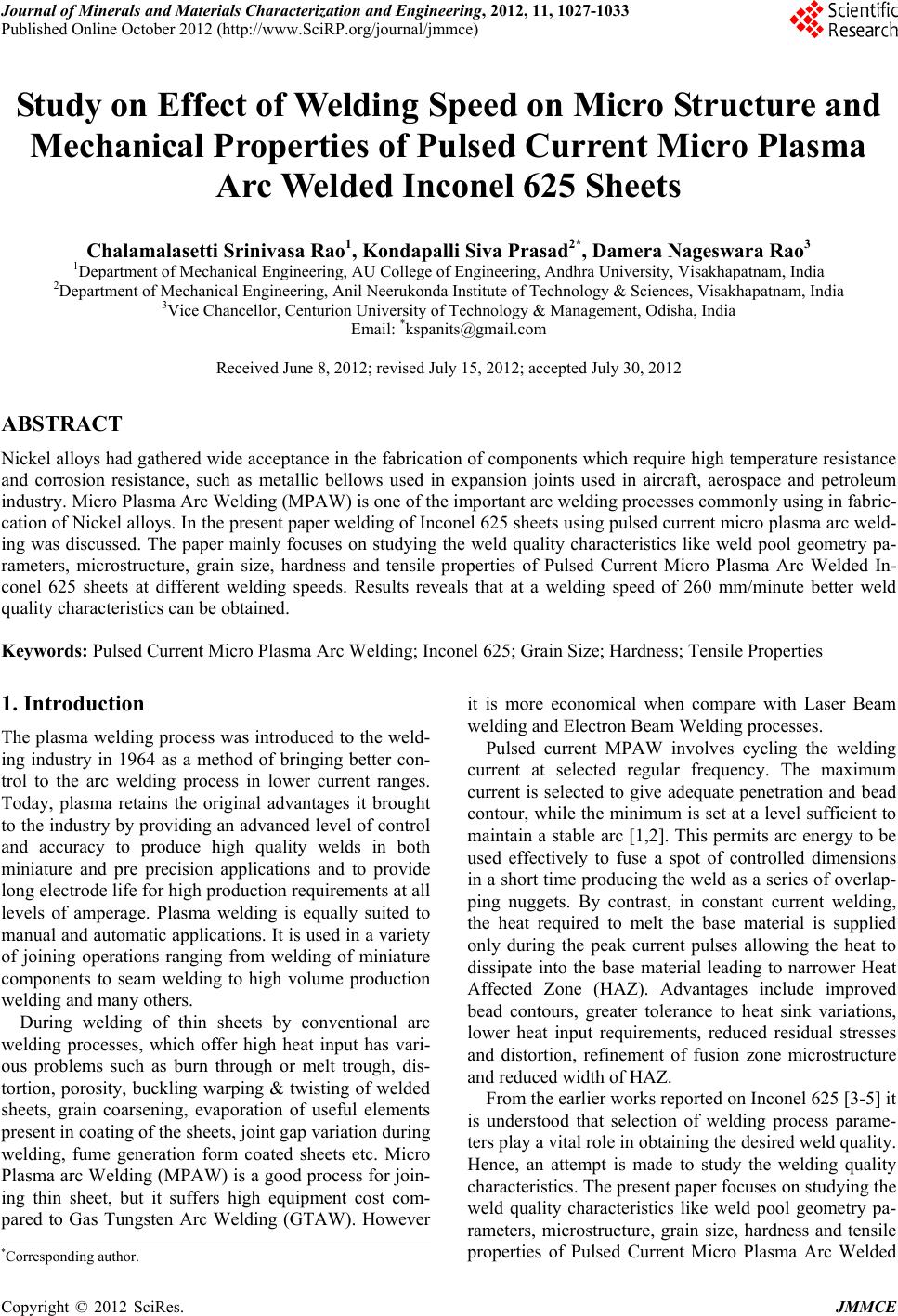
ing was discussed. The paper mainly focuses on studying the weld quality characteristics like weld pool geometry pa-
rameters, microstructure, grain size, hardness and tensile properties of Pulsed Current Micro Plasma Arc Welded In-
conel 625 sheets at different welding speeds. Results reveals that at a welding speed of 260 mm/minute better weld
quality characteristics can be obtained.
Keywords: Pulsed Current Micro Plasma Arc Welding; Inconel 625; Grain Size; Hardness; Tensile Properties
1. Introduction
The plasma welding process was introduced to the weld-
ing industry in 1964 as a method of bringing better con-
trol to the arc welding process in lower current ranges.
Today, plasma retains the original advantages it brought
to the industry by providing an advanced level of control
and accuracy to produce high quality welds in both
miniature and pre precision applications and to provide
long electrode life for high production requirements at all
levels of amperage. Plasma welding is equally suited to
manual and automatic applicatio ns. It is used in a variety
of joining operations ranging from welding of miniature
components to seam welding to high volume production
welding and many others.
During welding of thin sheets by conventional arc
welding processes, which offer high heat input has vari-
ous problems such as burn through or melt trough, dis-
tortion, porosity, buckling warping & twisting of welded
sheets, grain coarsening, evaporation of useful elements
present in coating of the sheets, joint gap variation during
welding, fume generation form coated sheets etc. Micro
Plasma arc Welding (MPAW) is a good process for join-
ing thin sheet, but it suffers high equipment cost com-
pared to Gas Tungsten Arc Welding (GTAW). However
it is more economical when compare with Laser Beam
welding and Electron Beam Welding processes.
Pulsed current MPAW involves cycling the welding
current at selected regular frequency. The maximum
current is selected to give adequate penetration and bead
contour, while the minimum is set at a level sufficient to
maintain a stable arc [1,2]. This permits arc energy to be
used effectively to fuse a spot of controlled dimensions
in a short time produ cing the weld as a series of overlap-
ping nuggets. By contrast, in constant current welding,
the heat required to melt the base material is supplied
only during the peak current pulses allowing the heat to
dissipate into the base material leading to narrower Heat
Affected Zone (HAZ). Advantages include improved
bead contours, greater tolerance to heat sink variations,
lower heat input requirements, reduced residual stresses
and distortion, refinement of fusion zone microstructure
and reduced width of HAZ.
From the earlier works reported on In conel 62 5 [3-5] it
is understood that selection of welding process parame-
ters play a vital role in obtaining the d esired weld quality.
Hence, an attempt is made to study the welding quality
characteristics. The present paper focuses on studying th e
weld quality characteristics like weld pool geometry pa-
rameters, microstructure, grain size, hardness and tensile
properties of Pulsed Current Micro Plasma Arc Welded
*Corresponding author.
Copyright © 2012 SciRes. JMMCE
C. S. RAO ET AL.
1028
Inconel 625 sheets.
2. Experimental Procedure
Inconel 625 sheets of 100 × 150 × 0.25 mm are welded
autogenously with square butt joint without edge prepa-
ration. The chemical composition of Inconel 625 is given
in Table 1. High purity argon gas (99.99%) is used as a
shielding gas and a trailing gas right after welding to
prevent absorption of oxygen and nitrogen from the at-
mosphere. The welding has been carried out under the
welding condition s presented in Ta bl e 2 . There are many
influential process parameters which effect the weld
quality characteristics of Pulsed Current MPAW process
like peak current, back current, pulse rate, pulse width,
flow rate of shielding gas, flow rate of purging gas, flow
rate of plasma gas, welding speed etc. From the earlier
works [6-9] carried out on Pulsed Cu rrent MPAW it was
understood that the peak current, back current, pulse rate
and pulse width are the dominating parameters which
effect the weld quality characteristics. The values of
process parameters used in this study are the optimal
values obtained from our earlier papers [3-5]. Hence
peak current, back current, pulse rate and pulse width are
chosen and their values are presented in Table 3.
Table 1. Chemical composition of INCONEL 625 (weight
%).
C Mn P S Si Cr Ni
0.0300 0.0800 0.0050 0.00040.1200 20.8900 61.6000
Al Mo Cb Ta Ti N Co Fe
0.1700 8.4900 3.4400 0.0050 0.1800 0.0100 0.13004.6700
Table 2. Welding conditions.
Power source Secheron micro plasma arc machine
(model: PLASMAFIX 50E)
Polarity DCEN
Mode of operation Pulse mode
Electrode 2% thoriated tungsten electrode
Electrode diameter 1 mm
Plasma gas Argon & hydrogen
Plasma gas flow rate 6 Lpm
Shielding gas Argon
Shielding gas flow rate 0.4 Lpm
Purging gas Argon
Purging gas flow rat e 0.4 Lpm
Copper nozzle diameter 1 mm
Nozzle to plate distance 1 mm
Welding speed 260 mm/min
Torch Position Vertical
Operation type Automatic
Table 3. Important weld parameters.
Serial No.Input factor Units Value
1 Peak current Amperes 7
2 Back current Amperes 4
3 Pulse rate Pulses/second 40
4 Pulse width % 50
2.1. Measurement of Weld Bead Geometry
Sample preparation and mounting was done as per
ASTM E 3-1 standard. The samples were cut from the
welded specimens and mounting using Bakelite powder.
After standard metallurgical polishing process, aqua re-
gia is used as the etchant to reveal weld bead geometry.
The weld pool geometries were measured using Metal-
lurgical Microscope, Make: Dewinter Technologie, Mo-
del No. DMI-CROWN-II. A typical weld bead geometry
is shown in Figure 1.The measured values of weld pool
geometry are presented in Table 4.
Figures 2(a)-(d) indicate the back surface of the
welded joint at welding speeds of 150, 200, 260 & 300
mm/minute respectively.
2.2. Microstructure Measurement
For Microstructure measurement ASTM E 407 was fol-
lowed for Etching along with ASM Metal Hand Book,
Volume 9. For revealing the Microstructure the weld
samples are mounted using Bakelite and polishing was
done according to standard Metallurgical procedure.
Aqua Regia was used as an etchant. For revealing the
Microstructure, Electrolytic Etching was done. The Mi-
crostructure was measured using Metallurgical Micro-
scope at a magnification of 100×. Figures 3(a)-(d) indi-
cates the microstructures at welding speeds of 150, 200,
260 & 300 mm/minute respectively. The left portion in
the Figures 3(a)-(d) indicates weld fusion zone ad right
portion indicates Heat Affected Zone (HAZ).
2.3. Grain Size Measurement
In order to reveal the grains, polishing was done accord-
ing to standard Metallurgical procedure and Etching was
done as per ASTM E407. Electrolytic was done using
Aqua Regia for about 1 minute. Scanning Electron Mi-
croscope, Make: INCA Penta FETx3, Model: 7573 as
shown in Figure 4 is used to measure the fusion zone
grain size and parent metal. Figures 5(a)-(d) indicates
the fusion zone grain size at welding speeds of 150, 200,
260 & 300 mm/minute respectively. As the grains in
some parts of the weld fusion zone are elongated and
uneven, an average value was reported by measuring
grain size at different locations in the fusion zone of each
sample.
Copyright © 2012 SciRes. JMMCE
C. S. RAO ET AL.
Copyright © 2012 SciRes. JMMCE
1029
Table 4. Variation of hardness values across the weld joint at 0.3 mm interval.
Hardness values in VHN at different locations on the weld joint
HAZ zone Fusion zone HAZ zone
Elding speed
(mm/ minut e)
1 2 3 4 5 6 7 8 9
150 260.7 258.4 229.3 242.0 241.9 248.8 250.8 249.3 255.2
200 242.4 255.6 254.6 238.2 231.9 240.0 255.0 240.1 234.2
260 247.8 255.5 242.3 248.1 262.4 249.5 260.6 256.6 244.0
300 232.2 238.5 250.1 239.9 253.9 236.3 255.0 238.4 226.5
3. Results & Discussions
3.1. Weld Pool Geometry
From Table 5 and from Figures 2(a)-(d) it is noticed
that at the welding speed of 150 mm/minute over melting
of base metal was noticed and when the welding speed of
300 mm/minute there is improper fusion of the base
metal. At the welding speed of around 260 mm/min op-
timum weld pool geometry parameters are obtained.
3.2. Fusion Zone Grain Size
Figure 1. Typical weld bead geometry. The variation of fusion zone grain size with respect to
welding speed was presented in Figure 12. It is noticed
that the grain size decreased up to a welding speed of 260
mm/minute and there after increased. This is due to im-
proper fusion of base metal.
2.4. Measurement of Vickers Micro Hardness
Vickers Micro hardness was done as per ASTM E384.
The samples were cut from the welded specimens and
Vickers Micro Hardness values across the weld joint at
an interval of 0.3 mm using Digital Micro Hardness test-
ing Machine, make METSUZAWA CO LTD, JAPAN,
Model No: MMT-X7 as shown in Figure 6.
3.3. Fusion Zone Hardness
The variation of fusion zone hardness with respect to
welding speed was presented in Figure 13. It is noticed
that the hardness increases gradually up to 252.58 VHN
at welding speed of 260 mm/minute and there after de-
creases to 247.04 VHN, when the welding speed is 300
mm/minute.
In the Table 4 points 1, 2, 8, 9 indicates at Heat Af-
fected Zone (HAZ) and the points 3, 4, 5, 6, 7 indicate at
Fusion Zone (FZ). The location of the hardness mea-
suring points is shown in Figure 7. The variation of
hardness across the weld is shown in Figure 8.
From Table 4 and Figure 8 it understood that hard-
ness at centre of FZ is less and it keeps on increasing
towards HAZ.
3.4. Ultimate Tensile Strength
The variation of ultimate tensile strength with respect to
welding speed was presented in Figure 14. It is noticed
that the ultimate tensile strength increases gradu ally up to
857 MPa at welding speed of 260 mm/minute and there
after decreases to 837 MPa, when the welding speed is
300 mm/minute.
2.5. Measurement of Ultimate Tensile Strength
Three transverse tensile specimens are prepared as per
ASTM E8M-04 guidelines and the specimens after wire
cut Electro Discharge Machining are shown in Figure 9
and 10. Tensile tests are carried out in 100 kN computer
controlled Universal Testing Machine (ZENON, Model
No: WDW-100) as shown in Figure 11. The specimen is
loaded at a rate of 1.5 kN/min as per ASTM specifica-
tions, so that the tensile specimens undergo deformation.
From the stress strain curve, the yield and ultimate ten-
sile strength of the weld joints is evaluated and the aver-
age of three results is presented in Table 5.
4. Conclusion
Inconel 625 sheets are successfully welded using pulsed
current MPAW process at different welding speeds.
From the experiments performed, it is revealed that
sound weld pool geometry is obtained at the welding
speed of 260 mm/minute. Fusion zone grain size de-
creased from welding speed of 150 mm/minute to 300
C. S. RAO ET AL.
1030
(a) (b)
(c) (d)
Figure 2. (a) welding speed of 150 mm/minute; (b) welding speed of 200 mm/minute; (c) welding speed of 260 mm/minute; (d)
welding speed of 300 mm/minute.
(a) (b)
(c) (d)
Figure 3. (a) welding speed of 150 mm/minute; (b) welding speed of 200 mm/minute; (c) welding speed of 260 mm/minute; (d)
welding speed of 300 mm/minute.
Copyright © 2012 SciRes. JMMCE
C. S. RAO ET AL. 1031
Figure 4. Scanning electron microscope.
(a)
(b)
(c)
(d)
Figure 5. (a) Welding Speed of 150 mm/minute; (b) Welding
speed of 200 mm/minute; (c) Welding speed of 260 mm/mi-
nute; (d) Welding speed of 300 mm/minute.
Figure 6. Vickers micro hardness tester.
Figure 7. Location of hardness measuring points on the
weld joint.
Location on weld joint
Figure 8. Variation of hardness across the weld.
Copyright © 2012 SciRes. JMMCE
C. S. RAO ET AL.
1032
Figure 9. Schematic diagram of tensile specimen as per
ASTM E8.
Figure 10. Tensile specimens of inconel 625 welded joints.
Figure 11. Universal testing machine.
Figure 12. Variation of fusion zone grain size.
Figure 13. Variation of fusion zone hardness.
Figure 14. Variation of ultimate tensile strength.
Table 5. Comparison of weld quality characteristics.
Weld pool Geometry
Welding Speed
(mm/minute) Front Width Back Width Front HeightBack Height
Fusion Zone grain
size (Microns)
Fusion Zone
hardness
(VHN)
Ultimate
Strength
(MPa)
150 1.231 1.171 0.0458 0.0358 63.956 242.56 790
200 1.253 1.188 0.0475 0.0376 50.528 243.94 829
260 1.270 1.202 0.0456 0.0356 45.774 252.58 857
300 1.153 1.075 0.0470 0.0366 52.713 247.04 837
mm/minute, where as fusion zone hardness and ultimate
tensile strength increased with welding speed up to 260
mm/minute and thereafter decreased. From the results on
various weld quality characteristics tests, it is understood
that at the welding speed of 260 mm/minute, optimal
weld quality characteristics are obtained.
Copyright © 2012 SciRes. JMMCE
C. S. RAO ET AL. 1033
5. Acknowledgments
The authors would like to thank Shri. R.Gopla Krishnan,
Director, M/s Metallic Bellows (I) Pvt Ltd, Chennai for
his support to carry out experimentation work.
REFERENCES
[1] M. Balasubramanian, V. Jayabalan and V. Balasubrama-
nian, “Effect of Process Parameters of Pulsed Current
Tungsten Inert Gas Welding on Weld Pool Geometry of
Titanium Welds,” Acta Metallurgica Sinica (English Let-
ters), Vol. 23, No. 4, 2010, pp. 312-320.
[2] B. Balasubramanian, V. Jayabalan and V. Balasubrama-
nian, “Optimizing the Pulsed Current Gas Tungsten Arc
Welding Parameters,” Journal of Materials Science &
Technology, Vol. 22, No. 6, 2006, pp. 821-825.
[3] K. S. Prasad, C. S. Rao and D. N. Rao, “Optimizing
Pulsed Current Micro Plasma Arc Welding Parameters to
Maximize Ultimate Tensile Strength of Inconel 625
Nickel Alloy Using Response Surface Method,” Interna-
tional Journal of Engineering, Science and Technology,
Vol. 3, No. 6, 2011, pp. 226-236.
[4] K. S. Prasad, C. S. Rao and D. N. Rao, “Optimizing Fu-
sion Zone Grain Size and Ultimate Tensile Strength of
Pulsed Current Micro Plasma Arc Welded Inconel 625
Alloy Sheets Using Hooke & Jeeves Method,” Interna-
tional Transaction Journal of Engineering, Management,
& Applied Sciences & Technologies, Vol. 3, No. 1, 2012,
pp. 87-100.
[5] K. S. Prasad, C. S. Rao a nd D. N. Rao, “Effect of Process
Parameters of Pulsed Current Micro Plasma Arc Welding
on Weld Pool Geometry of Inconel 625 Welds,” Kovove
MaterialyMetallic Materials, Vol. 50, No. 3, 2012, pp.
153-159 (in press).
[6] R. Manti, D. K. Dwivedi and A. Agarwal, “Microstruc-
ture and Hardness of Al-Mg-Si Weldments Produced by
Pulse GTA Welding,” The International Journal of Ad-
vanced Manufacturing Technology, Vol. 36, No. 3-4,
2008, pp. 263-269. doi:10.1007/s00170-006-0849-z
[7] T. S. kumar, V. Balasubramanian, S. Babu and M. Y.
Sanavullah, “Effect of Pulsed Current GTA Welding Pa-
rameters on the Fusion Zone Microstructure of AA 6061
Aluminium Alloy, Metal and Materials International,
Vol. 13, No. 4, 2007, pp. 345-351.
[8] N. Karunakaran and V. Balasubramanian, “Effect of
Pulsed Current on Temperature Distribution, Weld Bead
Profiles and Characteristics of Gas Tungsten Arc Welede
Aluminium Alloy Joints,” Transactions of Nonferrous
Metals Society of China, Vol. 21, No. 2, 2011, pp. 278-
286. doi:10.1016/S1003-6326(11)60710-3
[9] G. Padmanaban and V. Balasubramanian, “Influences of
Pulsed Current Parameters on Mechanical and Metallur-
gical Properties of Gas Tungsten Arc Welede AZ31B
Magnesium Alloy,” Metals and Materials International,
Vol. 17, No. 4, 2011, pp. 679-687.
doi:10.1007/s12540-011-0826-4
Copyright © 2012 SciRes. JMMCE