Paper Menu >>
Journal Menu >>
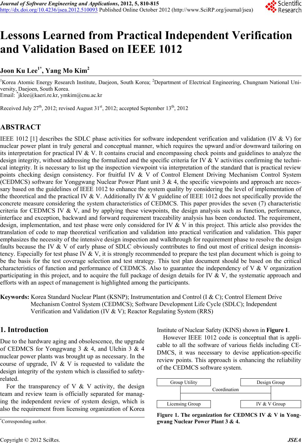 Journal of Software Engineering and Applications, 2012, 5, 810-815 http://dx.doi.org/10.4236/jsea.2012.510093 Published Online October 2012 (http://www.SciRP.org/journal/jsea) Lessons Learned from Practical Independent Verification and Validation Based on IEEE 1012 Joon Ku Lee1*, Yang Mo Kim2 1Korea Atomic Energy Research Institute, Daejeon, South Korea; 2Department of Electrical Engineering, Chungnam National Uni- versity, Daejoen, South Korea. Email: *jklee@kaeri.re.kr, ymkim@cnu.ac. kr Received July 27th, 2012; revised August 31st, 2012; accepted September 13th, 2012 ABSTRACT IEEE 1012 [1] describes the SDLC phase activities for software independent verification and validation (IV & V) for nuclear power plant in truly general and conceptual manner, which requires the upward and/or downward tailoring on its interpretation for practical IV & V. It contains crucial and encompassing check points and guidelines to analyze the design integr ity, without addressing the formalized an d the specific criteria for IV & V activities confirming th e techni- cal integrity. It is necessary to list up the inspection viewpoint via interpretation of the standard that is practical review points checking design consistency. For fruitful IV & V of Control Element Driving Mechanism Control System (CEDMCS) softw are for Yonggwang Nuclear Powe r Plant unit 3 & 4, the specific viewpoints and appr oach are neces- sary based on the guidelines of IEEE 1012 to enhance the system quality by considering the level of implementation of the theoretical and the practical IV & V. Additionally IV & V guideline of IEEE 1012 does not specifically provide the concrete measure considering the system characteristics of CEDMCS. This paper provides the seven (7) characteristic criteria for CEDMCS IV & V, and by applying these viewpoints, the design analysis such as function, performance, interface and exception, backward and forward requirement traceability analysis has been conducted. The requirement, design, implementation, and test phase were only considered for IV & V in this project. This article also provides the translation of code to map theoretical verification and validation into practical verification and validation. This paper emphasizes the necessity of the intensive design inspection and walkthrough for requirement phase to resolve the design faults because the IV & V of early phase of SDLC obviously contributes to find out most of critical design inconsis- tency. Especially for test phase IV & V, it is strongly recommended to prepare the test plan docu ment which is going to be the basis for the test coverage selection and test strategy. This test plan document should be based on the critical characteristics of function and performance of CEDMCS. Also to guarantee the independency of V & V organization participating in this project, and to acquire the full package of design details for IV & V, the systematic approach and efforts with an aspect of management is highlighted among the participants. Keywords: Korea Standard Nuclear Plant (KSNP); Instrumentation and Control (I & C); Control Element Drive Mechanism Control System (CEDMCS); Software Development Life Cycle (SDLC); Independent Verification and Validation (IV & V); Reactor Regulating System (RRS) 1. Introduction Due to the hardware aging and obsolescence, the upgrade of CEDMCS for Yonggwang 3 & 4, and Ulchin 3 & 4 nuclear power plants was brought up as necessary. In the course of upgrade, IV & V is requested to validate the design integrity of the system which is classified to safety- related. For the transparency of V & V activity, the design team and review team is officially separated for manag- ing the independent review of system design, which is also the requirement from licensing organization of Korea Institute of Nuclear Safety (KINS) shown i n Figure 1. However IEEE 1012 code is conceptual that is appli- cable to all the software of various fields including CE- DMCS, it was necessary to devise application-specific review points. This approach is enhancing the reliability of the CEDMCS software system. Group Utility Design Group Coordination Licensing Group IV & V Group Figure 1. The organization for CEDMCS IV & V in Yong- gwang Nuclear Power Plant 3 & 4. *Corresponding a uthor. Copyright © 2012 SciRes. JSEA  Lessons Learned from Practical Independent Verification and Validation Based on IEEE 1012 811 2. IV & V of CEDMCS in KSNP CEDMCS on Korea Standard Nuclear Plant (KSNP) was independently verified and validated. Based on the con- ceptual IV & V activities of IEEE 1012, the major view- point is selected as below through the system function and performance analysis of CEDMCS. 1) Identification of the critical functional characteris- tics for the CEDMCS; 2) Identification of the interface between the internal and external sub-components like the communication and its transmissi on frequency (i ncluding the serial data links); 3) Identification of the performance characteristics for the target system; 4) Identification of the appropriateness on the functional cohesion and coupling for fina l im plem entation [1,2] ; 5) Reliability of the function and performance; 6) Exceptional handling; 7) Identification of the test coverage. The following section will address the d etail o f the it e m enumerated above. 2.1. Identification of Critical Characteristics There are following design factors for CEDMCS, when an independent review is conducted. 1) Profile to drive the control rod up, down, and hold; 2) Conditions that interlock the rod driving; 3) Engagement condition for the rod driving; 4) Operation mode of the rod driving. In addition to the above, th ere are many design factors for controlling rods which are regulated by CEDMCS. These factors are identified as critical design characteristics and should be highlighted when an independent review is conducted. Figure 2 indicates the interconnection diagram between CEDMCS and other auxiliary system which provides the control input and output. The CEDMCS marked with cloud in Figure 2 is to control the reactivity by insertion and withdrawal o f control rod. The main inpu t from RRS is the control signal, and rod is also controlled by operator intervention. Thus integral IV & V is the critical task to guarantee the integrity of the system. Otherwise CE- DMCS causes the plant trip bringing about the financial damage and public hazard. 2.2. Identification of the Interface For the modernization or upgrade of CEDMCS, some of the hardwired interconnections between components are connected through a communication network. The main differences between these two configurations are discon- tinuity and continuity of data. In case of hardwired, the continuity of data is guaranteed, but when communica- tion is used for data exchange, there might be a disconti- nuity of data when a network failure occurs and is recov- ered soon. 2.3. Identification for Performance Characteristic As mentioned above 1) in 2.1, the profile should be im- plemented according to the tolerable range in time line. This could results in critical hazard of malfunction in in- sertion, withdrawal and holding of rod. Figure 2. CEDMCS in Yonggwang Nuclear Power Plant 3 & 4. Copyright © 2012 SciRes. JSEA  Lessons Learned from Practical Independent Verification and Validation Based on IEEE 1012 812 2.4. Cohesion and Coupling It is the design verification to check if the software mo- dule is constructed well based on the logical function de- composition, getting rid of implementation complexity and ambiguity that result from bad software design. It is a critical measure to judge the testability and maintain- ability of software [2]. 2.5. Reliability of Function and Performance It is a new aspect of verification and validation to check if the function to be implemented is implementable as software or hardware. Recently most of functions, even implemented with hardware in a legacy plant, are re- formed as software, targeting a digital system. 2.6. Exception Handling In any software function, there is an exception of partial function. This partial function shall be clearly designed and implemented, which supports a reliable test plan and procedure in the test phase. 2.7. Test Coverage Practically exhaustive test coverage is not desirable and recommended for robust software testing. However, when the output of the software is actuating the hardware de- vice that is connected, the maximum test coverage is recommended in test. For this systematic and concrete test coverage has been generated by designer as well as IV & V reviewer based on the 7 criteria. It was very helpful to remove the delicate failure sources, which was the solid platform of test procedure. Based on the fundamental principles mentioned in IEEE 1012, the IV & V team extracts and summarizes the non-trivial points for verification and validation as described in 2.1 through 2.7, which is used for estimating the design integrity of whole CEDMCS system except hardware design and assembly part. 3. Statistical Distribution of Anomaly Data The following is a number of anomaly reports issued at the each phase of SDLC, excluding the planning, instal- lation and maintenance for simplicity. Tables 1 and 2 show the anomaly pattern of each design segment thro- ughout software development life cycle. As shown, most of design anomaly is identified in the early phase of re- quirement and design. And even thought that the number of anomaly is not so significant, most of anomaly topic in test phase is the coverage and the scope of each testing such as unit testing, integration testing, Factory Accep- tance Testing (FAT) and Site Acceptance Testing (SAT). Figure 3 is indicating the amount of the anomaly for each design segment in total. There are several issues that we need to be aware of. The extent of Line of Code (LOC) and complexity of design is closely related to a number of anomalies, and especially the design segment of Man Machine Interface (MMI) that has human inter- face is relatively high number of Human Factor (HF) anomaly. Even though HF can be viewed as a different side of IV & V, ther e is obviou sly a tenden cy that th e HF design is significantly overlooked in the design process. Table 1. Anomaly pattern of CEDMCS software upgrade in Yonggwang Nuclear Power Plant 3 & 4. Req’t Design Impl.Test Logic Controller 17 7 5 5 Logic Controller MTP 8 9 5 8 PC and DCHC Controller 2 5 4 3 PC and DCHC Controller FPGA 3 5 2 0 MCB OM 16 3 4 3 Total 71 78 29 23 Table 2. Anomaly pattern of CEDMCS software upgrade in Ulchin Nucle a r Power Pla nt 3 & 4. Req’t Design Impl.Test Logic Controller 10 8 6 5 Logic Controller MTP 12 14 9 4 SSPE Power Controller 5 10 1 2 SSPE Power Controller FPGA 4 5 0 0 Data Process Controller 21 21 5 5 Data Process Controller MTP 19 20 8 7 Total 71 78 29 23 Figure 3. Diagram for AR distribution in Yonggwang Nu- clear Power Plant 3 & 4. Copyright © 2012 SciRes. JSEA  Lessons Learned from Practical Independent Verification and Validation Based on IEEE 1012 813 4. Lesson Learned in V & V of KSNP CEDMCS The following is the pattern found through the analysis of anomaly reports in each phase about CEDMCS of Yon- ggwang unit 3 & 4, and Ulchin unit 3 & 4 nuclear power plants. 4.1. High Level Design Error Most of errors were found in the early stage of software development life cycle [3,4]. Requirement and design phases in SDLC are much more important in software development as indicated in Tables 1 and 2, and Figure 3. The fault of early phase design can cause the wrong implementation which is not verified because it is well designed based on the wrong early phase of design. The small number of anomaly in the phase behind requirement phase is truly based on the early stage of development phase. For requirement IV & V, the contract, project planning documents, user (utility) requirements, technical meeting minutes, system design documents such as System Re- quirement (SR), Design Requirement (DR), Design Spe- cification (DS), and Interface Requirement (IR), Perfo- rmance Requirement (PR) and other design relevant doc- uments were used for requirement phase IV & V input. 4.2. The Test Preparation of CEDMCS With the result of requirement phase IV & V, the design and implementation phase is conducted without remark- able controversy. But in test phase, the hot debate for test coverage and plan has been done. The outstanding devia- tion between designer and IV & V reviewer was identi- fied. To resolve these issues, each participating organiza- tion together had a meeting, and decided to prepare the test plan document based on IEEE code [5,6]. 4.3. The Management of IV & V According to Annex C “definition of independent V & V (IV & V)” of IEEE 1012-2004 [1], IV & V is defined by three parameters: technical independence, managerial in- dependence, and financial independence as described in Table 3. Table 3. Independent verific a tion and validation for m . IV & V Form Technical Management Financial Classical I I I Modified I i I Integrated i I I Internal i i i Embedded e e e Note: I: Rigorous; i: Conditional Independence; e: M inimal Independence. 4.3.1. Technical Independence Technical independence requires the V & V effort to util- ize personnel who are not involved in the development of the software. The IV & V effort should formulate its own understanding of the problem and how the proposed sys- tem is solving the problem. Technical indepen d en c e ( “f r es h viewpoint”) is an important method to detect subtle errors overlooked by those too close to t he solution. For software tools, technical independence means that the IV & V effort uses or develops its own set of test and analysis tools separate from the developer’s tools. But this type of tool independence is overlooked in this pro- ject for the reason of milestone, budget and suspicion that diverse and independent tool environment does not exactly guarantee the correctness and reliability of the system. 4.3.2. Manage r ial Indepe n dence Managerial independence requires that the responsibility for the IV & V effort be vested in an organization sepa- rate from the development and program management organizations. Managerial independence also means that the IV & V effort independently selects the segments of the software and system to analyze and test, chooses the IV & V techniques, defines the schedule of IV & V ac- tivities, and selects the specific technical issues and prob- lems to act upon. The IV & V effort provides its findings in a timely fashion simultaneously to both the develop- ment and program management organizations. The IV & V effort must be allowed to submit to program manage- ment the IV & V results, anomalies, and findings without any restrictions (e.g., without requiring prior approval from the development group) or adverse pressures, direct or indirect, from the development group. In this project this independence is kept almost in perfect manner via technical meeting and managerial meeting continuously. 4.3.3. Financial Independen ce Financial Independence requires that control of the IV & V budget be vested in an organization independent of the development organization. This independence prevents situations where the IV & V effort cannot complete its analy- sis, or test or deliver timely results because funds have been diverted or adverse financial pressures or influences have been exerted. This is totally evident and there is no way out from this dilemma in this project. 4.3.4. Forms of Indep en dence The extent to which each of the three independence pa- rameters (technical, managerial, financial) is vested in a V & V organization determines the degree of indepen- dence achieved. Many forms of independence can be adopted for a V & V organization. The five most prevalent are: 1) Clas- Copyright © 2012 SciRes. JSEA 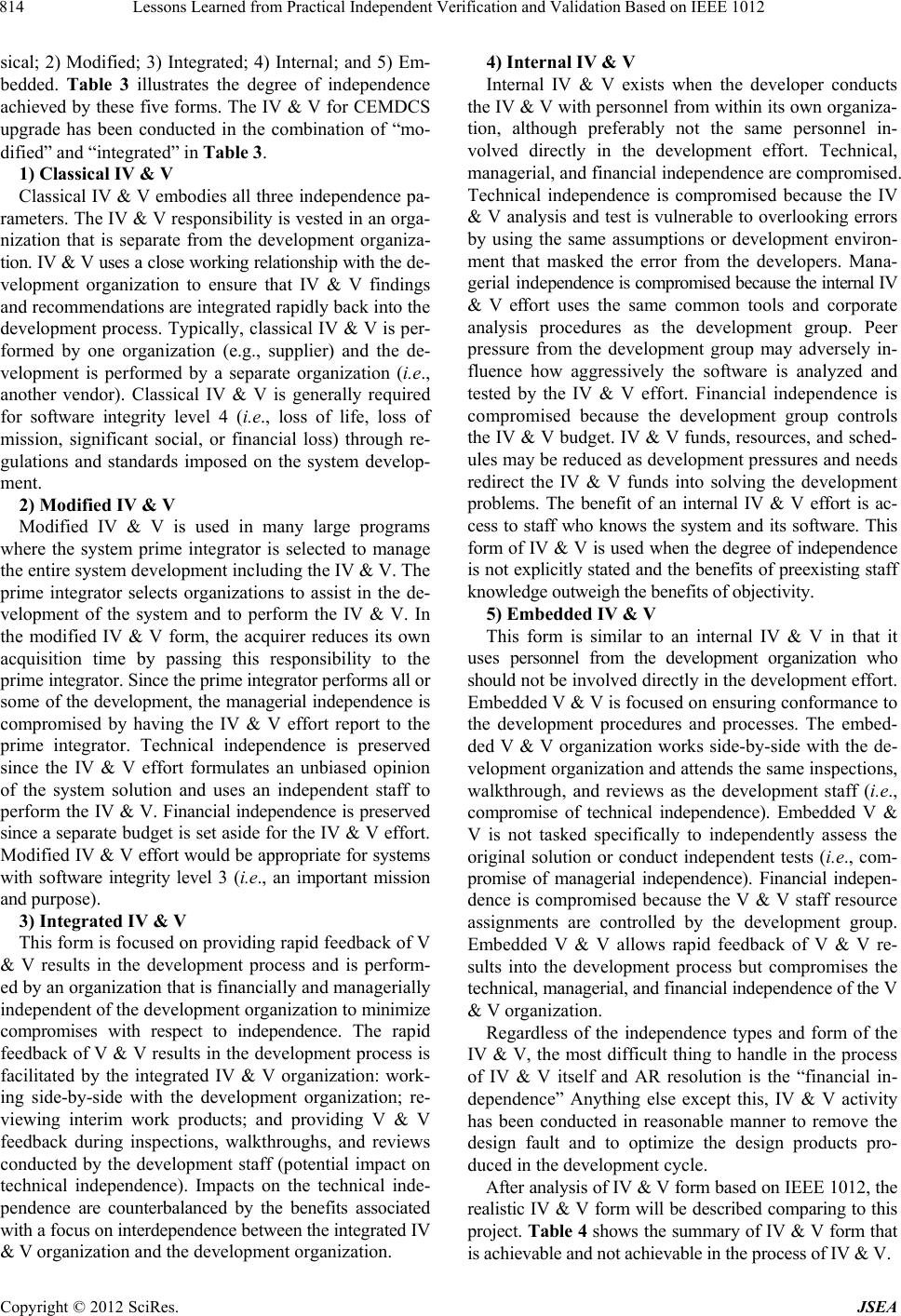 Lessons Learned from Practical Independent Verification and Validation Based on IEEE 1012 814 sical; 2) Modified; 3) Integrated; 4) Internal; and 5) Em- bedded. Table 3 illustrates the degree of independence achieved by these five forms. The IV & V for CEMDCS upgrade has been conducted in the combination of “mo- dified” and “integrated” in Table 3. 1) Classical IV & V Classical IV & V embodies all three independence pa- rameters. The IV & V responsibility is vested in an orga- nization that is separate from the development organiza- tion. IV & V uses a clo se working relation ship wi th the d e - velopment organization to ensure that IV & V findings and recommendations are integrated rapidly back into the development process. Typically, classical IV & V is per- formed by one organization (e.g., supplier) and the de- velopment is performed by a separate organization (i.e., another vendor). Classical IV & V is generally required for software integrity level 4 (i.e., loss of life, loss of mission, significant social, or financial loss) through re- gulations and standards imposed on the system develop- ment. 2) Modified IV & V Modified IV & V is used in many large programs where the system prime integrator is selected to manage the entire system develo pment in clud ing the IV & V. The prime integrator selects organizations to assist in the de- velopment of the system and to perform the IV & V. In the modified IV & V form, the acquirer reduces its own acquisition time by passing this responsibility to the prime integrator. Since the prime i ntegrator perform s al l or some of the development, the managerial independence is compromised by having the IV & V effort report to the prime integrator. Technical independence is preserved since the IV & V effort formulates an unbiased opinion of the system solution and uses an independent staff to per form the IV & V. Financial independence is preserved since a separate budget is set aside for the IV & V effort. Mod ified IV & V effort would be appropriate for systems with software integrity level 3 (i.e., an important mission and purpose). 3) Integrated IV & V This form is focused on providing rapid feedback of V & V results in the development process and is perform- ed by an organization that is financially and managerially independent of the development organization to minimize compromises with respect to independence. The rapid feedback of V & V results in the development process is facilitated by the integrated IV & V organization: work- ing side-by-side with the development organization; re- viewing interim work products; and providing V & V feedback during inspections, walkthroughs, and reviews conducted by the development staff (potential impact on technical independence). Impacts on the technical inde- pendence are counterbalanced by the benefits associated with a focus on interdep endence between th e integrated IV & V organization and the development organization. 4) Internal IV & V Internal IV & V exists when the developer conducts the IV & V with personnel from within its own o rganiza- tion, although preferably not the same personnel in- volved directly in the development effort. Technical, managerial, and financial independence are compromised. Technical independence is compromised because the IV & V analysis and test is vulnerable to overlooking errors by using the same assumptions or development environ- ment that masked the error from the developers. Mana- g e r i al i n d e pendence is compromised because the internal IV & V effort uses the same common tools and corporate analysis procedures as the development group. Peer pressure from the development group may adversely in- fluence how aggressively the software is analyzed and tested by the IV & V effort. Financial independence is compromised because the development group controls the IV & V budget. IV & V fu nds, resources, and sch ed- ules may be reduced as development pressures and needs redirect the IV & V funds into solving the development problems. The benefit of an internal IV & V effort is ac- cess to staff who knows the system and its software. This form of IV & V is used when the degree of independence is not explicitly stated and the benefits of preexisting staff knowledge outweigh t he benefits of objecti vity . 5) Embedded IV & V This form is similar to an internal IV & V in that it uses personnel from the development organization who should not be involved directly in the develop ment effort. Embedded V & V is focused on ensuring conformance to the development procedures and processes. The embed- ded V & V organization works side-by-side with the de- velopment organization and attends the same inspections, walkthrough, and reviews as the development staff (i.e., compromise of technical independence). Embedded V & V is not tasked specifically to independently assess the original solution or conduct independent tests (i.e., com- promise of managerial independence). Financial indepen- dence is compromised because the V & V staff resource assignments are controlled by the development group. Embedded V & V allows rapid feedback of V & V re- sults into the development process but compromises the technical, managerial, and financial independence of the V & V organization. Regardless of the independence types and form of the IV & V, the most difficult thing to handle in the process of IV & V itself and AR resolution is the “financial in- dependence” Anything else except this, IV & V activity has been conducted in reasonable manner to remove the design fault and to optimize the design products pro- duced in the development cycle. After analysis of IV & V form based on IEEE 1012, the realistic IV & V form will be described comparing to this project. Ta ble 4 shows the summary of IV & V form that is achievable and not achievable in the process of IV & V. Copyright © 2012 SciRes. JSEA  Lessons Learned from Practical Independent Verification and Validation Based on IEEE 1012 Copyright © 2012 SciRes. JSEA 815 Table 4. Comparison between IEEE Std. 1012 and practical independent verifica tion and validation. IEEE Std. 1012 Practical IV & V Technical independence Achievable Achievable Managerial independence Achievable Achievable Financial independence Achievable Achievable, but partly influenced by adverse or distorted pressure Forms of independence The classic model of IV & V is desirable. The “integrated model” of IV & V is realistic. Financial independence seems to be tough to imple- ment in realistic project environment. Thus it could be a concern to regulator for IV & V for safety-related system. It is complicated issue which might involve legal sup- port. 5. Conclusions Yonggwang un it 3 & 4 and Ulchin unit 3 & 4 that is one of the KSNP are upgraded with new ha rdware where the CEDMCS software is running. For software reliability, independent verification and validation has b een condu ct ed throughout the SDLC. It was important to correctly ana- lyze and recognize the core function, performance and interface of CEDMCS to draw the seven (7) criteria for IV & V view points in starting point, which is used throughout the IV & V. These items were also prepared by identifying the hazardous failure event of CEDMCS [7]. The design result was reviewed to analyze the design error involved in the design process. They show that most of the design inconsistency o ccurs in the early stag e of the design process such as the requirement phase and the design phase. Thus special care for design inception phase is required via well-known practices like technical meeting design inspection and walkthrough, and design iteration. Regardless of the type of independency and IV & V, the sensitive difference between reality and standards is the aspect that it is difficult to overcome the circum- stance of financial independency in a sense that the main contractor provides the money. If it is necessary, the le- gal support will be an efficient way to overcome finan- cial independency. However the solution was technical meeting including licensing body in this project. Once the completion of IV & V, issuing the anomaly report, a resolution meeting between IV & Ver and desi- gner to obtain the optimal solutio n is held in every SDLC phases. Unfortunately there is a tendency that the desi- gner will not partly accept the anomaly issued just be- cause the function is anyway performed well even though there is room for optimization and documentation. In this case anomaly resolution process was efficiently and man- datorily used with the written verification and validation plan and procedure including anomaly report disposition procedure for app r oval . Before commencing the test phase IV & V, it was very important to create and review the test plan to extract the essential test coverage and test scope of unit testing, in- tegration testing, factory acceptance testing, and site ac- ceptance testing. Likewise the SDLC design process, IV & V for SDLC design process has been iterated for soft- ware quality enhancement through technical meeting for anomaly report resolution. The activities for resolving these topics are completed successfully, resulting in that CEDMCS software system is running without errors or failures so far. 6. Acknowledgements This work has been conducted with the support of Man- Machine Interface System (MMIS) group in Korea Ato- mic Energy Research Institute (KAERI), and reliability and nuclear engineering group in KOrea Reliability Tec- hnology System (KORTS). REFERENCES [1] IEEE Standard 1012™, “IEEE Standard for Software Verification and Validation,” 2004. http://standards.ieee.org/findstds/standard/1012-2004.html [2] R. S. Pressman, “Software Engineering, a Practitioner’s Approach,” 5th Edition, McGraw-Hill Higher Education, New York, 2004. [3] K. H. Cha, K. C. Kwon and C. S. Woo, “The Software Verification and Validation Tasks for a Safety Critical System in Nuclear Power Plants,” International Journal of Safety, Vol. 3, No. 1, 2004, pp. 38-46. [4] C. Ponsard, P. Massonet, J. F. Molderez, A. Rifaut, A. van Lamsweerde and H. Tran Van, “Early Verification and Validation of Mission Critical Systems,” Formal Me- thods in System Design, Vol. 30, No. 3, 2004, pp. 233- 247. [5] IEEE Standard 829, “IEEE Standard for Software and System Test Documentation,” 2008. http://standards.ieee.org/findstds/standard/829-2008.html [6] IEEE Standard 1008, “IEEE Standard for Software Unit Testing,” 1987. http://standards.ieee.org/findstds/standard/1008-1987.html [7] NUREG/CR-6430, “Software Safety Hazard Analysis,” 1995. |