 Journal of Software Engineering and Applications, 2012, 5, 797-809 http://dx.doi.org/10.4236/jsea.2012.510092 Published Online October 2012 (http://www.SciRP.org/journal/jsea) 797 Software Measurement Methods: An Analysis of Two Designs Jean-Marc Desharnais, Alain Abran Department of Software Engineering and IT, École de Technologie Supérieure, Montreal, Canada. Email: desharnaisjm@gmail.com, alain.abran@etsmtl.ca Received August 22nd, 2012; revised September 24th, 2012; accepted October 6th, 2012 ABSTRACT In software engineering, software measures are often proposed without precise identification of the measurable concepts they attempt to quantify: consequently, the numbers obtained are challenging to reproduce in different measurement contexts and to interpret, either as base measures or in combination as derived measures. The lack of consistency when using base measures in data collection can affect both data preparation and data analysis. This paper analyzes the simi- larities and differences across three different views of measurement methods (ISO International Vocabulary on Metro- logy, ISO 15939, and ISO 25021), and uses a process proposed for the design of software measurement methods to analyze two examples of such methods selected from the literature. Keywords: Software Measures; Base Measures; Derived Measures; Measurement Method; Attributes; Software Quality Model; Metrology; Software Metrics 1. Introduction In the sciences and in engineering, the consensus on rigo- rous measurement definitions and base quantities is well established. For instance, the ISO 2007 edition on me- trology, the International Vocabulary of Metrology—Basic and General Concepts and Associated Terms [1], pre- sents 144 measurement terms in five categories and in increasing order of complexity (in parentheses, the num- ber of terms in each category) [2]: Quantities and Units (30 terms); Measurements (53 terms); Devices for measurement (12 terms); Properties of measuring devices (31 terms), and Measurement Standards - Etalons (18 terms). In the International System (SI) of units, there are 7 base quantities (length, mass, temperature, luminous in- tensity, time, etc.), from which all other quantities in the sciences and in engineering are derived. Of these 7 base quantities, only time (and multiples of its base unit, the second) is used in software engineering for the mea- surement of two project parameters: duration and effort. These parameters are then used in derived quantities, such as number of faults and number of tests, to represent some aspects of software quality, such as availability and modifiability. In the field of software engineering, and in ISO 9126 parts 1, 2, 3 and 4 [3-6], the single term metrics is often used in reference to multiple concepts: for example, the quantity to be measured (measurand1), the measurement procedure, the measurement results or models of rela- tionships across multiple measures, and measurement of the objects themselves. In the software engineering lite- rature, the term was, until recently, applied to: Measurement of a concept: e.g. cyclomatic complex- ity [2, ch. 7] [7]; Quality models: e.g. ISO 9126—software product quality [3-6]; Estimation models: e.g. Halstead’s effort equation [2, ch. 6] [8], Use Case Points—[2, ch. 9], COCOMO 1 and II, Boehm [9,10]; Cohesion and coupling [11-13]. In recent decades, hundreds of so-called software metrics have been proposed by researchers and practitioners alike, in both theoretical and empirical studies, for measuring software products and software processes [6-9]: most of these metrics were designed based either on intuition on the part of researchers, or on an empirical basis, or both, and they are often characterized by the ease with which some development process entities can be counted. The inventory of software metrics is at the present time so diversified and includes so many individual proposals that it is not seen as economically feasible for either the industry or the research community to investigate each of 1A measurand is defined as a particular quantity subject to measurement the specification of a measurand may require statements about quanti- ties such as time, temperature, and pressure [1]. Copyright © 2012 SciRes. JSEA  Software Measurement Methods: An Analysis of Two Designs 798 the hundreds of alternatives proposed to date. With the notable exception of the measurement of the functional size of software (ISO 19761 [14], ISO 14143 [15], etc.), no base measure for software has yet reached an international level of standardization. Initiatives to precisely define and develop international consensus on base measures for software and software quality are few and far between. For instance, there are still some no- ticeable differences in the vocabulary used for software measurement process in ISO 15939 [16] and ISO 9126 [3-6], compared with the measurement vocabulary adopted in the sciences and in engineering as a common taxonomy of measurement terms, including metrological terms like meter, lumen, degree Celsius, etc. [1]. The ISO 9126 quality model (and its successor, the ISO 25000 series [17], currently in preparation) for soft- ware products is well known among researchers and practitioners [18]. This quality model includes a submodel shared by the internal and external views of the quality of the software product, and a separate submodel for the quality-in-use of a software product. These two submodels include 10 quality characteristics, 27 subcharacteristics, and an inventory of over 250 derived measures proposed to quantify attributes of these quality characteristics and subcharacteristics. A number of measurement-related weaknesses have been identified in ISO 9126, such as the following: - There is no single list of base measures in ISO 9126: they are spread throughout the descriptions of the 250+ so-called metrics, which, according to the VIM, should be referred to as derived measures, that is: a combination of base measures [18]. - In [18], it was pointed out that these 250+ derived measures are based on what appears to be 80 distinct base measures [18]. - These 80 base measures lack a detailed description of the base quantities, the base units, and the attributes they are attempting to quantify. For some base measures in ISO 9126, in fact, it is difficult to figure out exactly what a measurable concept is, as it is variously and ambiguously referred to (as: a function, a question- naire, an item, a cost, an installation step, an opera- tion, etc.), which means that its definition is very much open to interpretation [18]. This problem in not unique to ISO 9126: in software engineering, the at- tributes to be measured are not often defined system- atically, as can be observed in ISO 24765—Vocabulary for systems and software engineers [19]: the term er- ror, for instance, has 4 definitions, defect has 3 defi- nitions, failure has 2 definitions, fault has 3 defini- tions, etc. Also, the definition of the attribute to be measured in [18] is only part of one of the necessary steps in the design of the measurement method for any attribute. For instance, no corresponding measure- ment method has been proposed for the base meas- ures introduced in ISO 9126, nor is there any indica- tion of what the measurement units might be. - The numerical rules for some of the proposed metrics are poorly defined, and include improper mixes of scale types [2, p. 220]. This ISO 9126 series is currently under revision by an ISO working group (ISO/IEC JTC1/SC7 WG6), and one of the challenges to improving its measurement results is to strengthen its foundations, including the set of base measures that are spread throughout Parts 2 - 4 of the series [3-6]. On the basis of the existing literature, this paper ana- lyzes the similarities and differences across three different views of measurement methods (ISO International Vo- cabulary on Metrology, ISO 15939, and ISO 25021). Comparing measurement views from these standards will allow researchers to carry out comparative studies of multiple alternative measures for the same attributes, and then to publish their studies and recommendations, so that industry has the necessary information on which to base their selection of a measurement method appropriate to their needs. We have no intention of proposing a spe- cific software measurement framework in this paper, even though it would be desirable to do so, but instead we aim to provide a better understanding of two measurement methods, in order to help software engineers obtain ac- curate, repeatable, and reproducible measurement results. This paper is organized as follows. Section 2 presents related work in software engineering, linking and com- paring the metrology concepts and terminology adopted in the International Vocabulary of Basic and General Terms in Metrology [1], ISO 15939 [16], and ISO/IEC 25021 [20]. Section 3 presents the four steps proposed by Abran [2] to design a measurement method. Section 4 analyzes the designs of two software measurement methods from the literature. Section 5 concludes the paper with a discussion. 2. Related Work on Measurement Concepts and Terminology 2.1. Metrology The domain of knowledge referred to as metrology forms the foundation for the development and use of measure- ment instruments and measurement processes in the sciences and in engineering. While metrology has a long tradition of use in, for example, physics and chemistry, it is rarely referred to in the software measurement literature. A notable exception in the software engineering literature is NIST (National Institute of Standards and Technology), which investi- gated “the underlying question of the nature of IT me- trology” in 1996 [21], and identified “opportunities to Copyright © 2012 SciRes. JSEA  Software Measurement Methods: An Analysis of Two Designs 799 advance IT metrology.” NIST proposed, for instance, “logical relationships between metrology concepts,” con- sisting of four steps to follow to obtain measured values: defining quantities/attributes, identifying units and scales, determining the primary references, and settling the secon- dary references. In addition, in 1999, Gray [22] discussed the applicability of metrology, and the necessity of ap- plying it, from the software measurement point of view: “We are still perhaps on the eve of giant steps in the new century for information technology. We will still need better measurements and more uniformity, precision, and control to achieve these giant steps.” Since then, metrology has been used for the design of the COSMIC measure- ment method, and is also addressed in [2]. 2.2. Measurement Definitions for the Practical View While in the software engineering literature, measure- ment is often defined as a mapping between two struc- tures, this does not give sufficient information about how to measure in practice. It was pointed out in [2,23] that it is necessary to move beyond the theoretical definition of the mapping to an operational procedure, as described in the vocabulary of the VIM [1] and modeled with a transi- tion through three levels for a practical view (Figure 1). A measurement principle forms the scientific basis of measurement. For software entities (products), the measure- ment principle involves the model(s) used as a basis to describe the concept that is related to a concept to quan- tify, and which can be quantified by a measurement method. The idea is that modeling, as a central notion in software products, should be considered at the same level as scientific principles in other sciences and in engineer- ing [2,23]. 2.3. Base Quantity and Measurement Method To adequately quantify a concept, a measurement method Figure 1. Measurement foundations [1,2]. is required, which itself must include a coherent set of definitions and measurement rules, as well as a base unit specific to the measurement method as described in the VIM [1]—Figure 2: A base unit is “a measurement unit that is adopted by convention for a base quantity” [1]. There is only one base unit for each base quantity. A measurement method is a generic operational de- scription, i.e. a description of a logical sequence of opera- tions for performing a measurement activity, for mov- ing on from the concept to quantify to the value repre- senting the measurement result [1, s. 2.5]. A measurement procedure is a set of operations, de- scribed specifically and used in the performance of par- ticular measurements according to a given method [1, s. 2.6]. A measurement method should be implemented con- cretely by some concrete operations achieved through measuring instruments and/or practical operations: selec- tion, counting, calculation, comparison, etc. This descrip- tion of a measurement according to one or more measure- ment principles and to a given measurement method is called the measurement procedure, which is more spe- cific, more detailed, and more closely related to the en- vironment and to the measuring instruments (e.g. tools) than the method, which is more generic. Measurable concept: functional size for length in the ISO 14143-1 standard [15]. Base quantity: 100 data movements in the COS- MIC measurement method. Base unit: a data movement from a single data group in the COSMIC measurement method. Concept to quantify: the Functional User Re- quirements (FUR) in the ISO 14143-1 standard. Symbol: CFP (COSMIC Function Points) in the COSMIC measurement method. Box A: Examples of some measurement terms in software engineering. Box A gives examples of a base quantity, a base unit, a concept to quantify, and a measurable concept. Note that the term metrics is avoided in the definitions above: although it is widely used in software engineering, Figure 2. A base quantity, as defined in the VIM [1]. Copyright © 2012 SciRes. JSEA  Software Measurement Methods: An Analysis of Two Designs 800 its use causes ambiguity, and possibly confusion, by sug- gesting erroneous analogies; therefore, this term is not used in this text. 2.4. Vocabulary Issues in ISO 15939 In 2002, the ISO documented and adopted a generic model for the measurement process in software organiza- tions in ISO 15939 [16] (revised in 2007). Specifically, ISO 15939 “identifies the activities and tasks that are necessary to successfully identify, define, select, apply, and improve software measurement within an overall project or organizational measurement structure” [16]. It also provides “definitions for measurement terms commonly used within the software industry,” using the VIM as its base, although with some tailoring of the terminology to facilitate it acceptance within the software engineering community. In ISO 15939, a base measure is “a measure defined in terms of an attribute and the method for quantifying it” [16]. The right-hand side of Figure 3 presents definitions of the terms adopted in this standard [16]. To obtain a base measure in practice, a measurement method must be applied to an attribute of an entity (i.e. an object which is itself a model of an object). In the VIM, a measurement method is defined as “a generic description of a logical organization of operations used in a measurement” [1, ref. 2.5], while in ISO 15939, this definition has been tailored as follows: “a logical se- quence of operations, described generically, used in quan- tifying an attribute with respect to a specified scale” [16]. Both definitions consider “a logical sequence/organization of operations,” and from this perspective they are similar. In ISO 15939, the attribute is a property of an entity. In [2], the entity refers to “the concept to quantify,” which should be related to a base unit [1]. The expression “base unit” cannot refer directly to the expression “base measure”, since a base unit is a part of a measurement method with rules and conventions designed to obtain a “base quan- tity.” In other words, a base quantity is a combination of a number from the numerical world and a base unit es- tablished by convention. For example, by international convention in the SI, the base quantity of length is Figure 3. A base measure, as defined in ISO 15939 [16]. composed of a number associated with the base unit “meter”. To date, there has been little work done to de- fine base units in software engineering, including base units for the measurement of the quality of a software. In software measurement, the COSMIC functional size mea- surement method in ISO 19761 is unique, in the sense that it has explicitly defined its base unit, referred to as “a data movement of a single data group,” and its corre- sponding measurement symbol, “CFP”. With this defini- tion, a COSMIC measurement can be expressed as a base quantity in the metrology sense with a number of base units (for example, 15 CFP, 27 CFP, etc.). In software engineering, the term time may refer to the number of months representing the base quantity for ex- pressing the concept of effort (as in productivity: soft- ware delivered per work effort unit, measured in per- son-months), or it may refer to the concept of duration (often measured in calendar-months). The interpretation of the measurement unit “month” will differ, depending on the concept to be represented and measured (e.g. per- son-months for the concept of human effort, and calen- dar-months for the concept of project duration). For the measurement of software quality, the measure- ment units of quality concepts, like faults, errors, defects, failures, etc., also need to be explicitly, and uniquely, de- fined. There are other similarities and differences in the terms used in the ISO 15939 and VIM vocabularies: 1) The concepts of fault, error, and defect: a) Can be associated with the term “attribute”, because they are properties or characteristics of an entity (i.e. software); b) But are difficult to quantify, even when there is a consensus on the corresponding base units (1 defect and 1 error, for example): it is not certain whether or not their identification is unique (reproducibility and repeatability problems). 2) The definitions of these “attributes” are generally high-level definitions without corresponding explicit mea- surement methods. 3) ISO 24765 (System and Software Engineering Vo- cabulary) [19] provides the following definitions: a) An error is defined as “a human action that pro- duces an incorrect result, such as software containing a fault”; b) A failure is defined as “an event in which a system or system component does not perform a required func- tion within specified limits”; c) A fault is defined as “a manifestation of an error in software”; d) A defect is defined as “a problem which, if not cor- rected, could cause an application either to fail or to pro- duce incorrect results [19]. Each of these definitions refers to another definition (e.g., an error contains a fault, and a fault is a manifesta- Copyright © 2012 SciRes. JSEA  Software Measurement Methods: An Analysis of Two Designs 801 tion of an error), which adds to the difficulty of quanti- fying concepts like these, and, based on these definitions, of obtaining accurate measurement results. The terms “concept to quantify” and “base quantity” are used in [1] instead of “attribute” and “base measure” respectively in [16,20]: Furthermore, if “defect” had been selected as a base unit in [16,20], this would mean that the concept of the defect was used both a base unit and a base quantity. It would be like using “length” and “meter” as a single concept, while they are clearly distinct concepts, but, of course, related in a well-organized relationship: “length” is the concept to be quantified, and “meter” is the base unit used for quantifying “length”. In conclusion, the definitions of “attribute” and “base measure” in [16,20] do not refer to an explicit definition of a base quantity, or to an explicit corresponding measure- ment unit. The proposal in [2] to use an explicit process to design a measurement method with its base measure (and corresponding base unit) can help improve measure- ment in software engineering, but the software engineer cannot expect the same precision in the short term as that provided by the International System of Units. 2.5. Vocabulary in ISO 25021 ISO 25021 [20] is a part of the ISO 25000 series, which is being published to update the ISO 9126 series [17]. ISO 25021 [20] has adopted a different vocabulary. For example, the new expression “Quality Measure Element (QME)” was substituted for “base measure”, and “pro- perty to quantify”, for the term “attribute”. On the right- hand side of Figure 4, a definition of each term has been added from the ISO 25021 vocabulary to help the reader understand the new terminology introduced. According to ISO 25021, the user of the measurement method shall identify and collect data related to the pro- perty to quantify (Figure 4). Depending on the context of usage and objective(s) of the Quality Measure Element Figure 4. A Quality Measure Element (QME), as defined in ISO 25021 [20]. (QME), a number of properties and sub properties can be identified. These properties constitute the input to the design of the measurement method, and are extracted and defined from the artifacts of the software (e.g., docu- mentation, code). This process2 is similar to the ISO 15939 process, but with a different terminology: “prop- erty to quantify” instead of “attribute”, and “quality measure element” instead of “base measure”. 2.6. Summary Mapping of the Three ISO Reference Documents A summary mapping of the measurement-related con- cepts defined in these three ISO reference documents is presented in Table 1. The metrology vocabulary (VIM) is adopted here, because it enjoys a wider consensus across the sciences and en- gineering than the adaptations in the other two docu- ments, which are limited to the software engineering community. 3. The Measurement Method In this section, the four steps recommended for designing a measurement method for a base quantity are described in more detail [2]. In Section 4, we analyze, using these steps, the design of two base quantities related to the quality of the software. To obtain a base quantity [1], it is not only necessary to apply a measurement method to the measurable con- cept, but also to use the base unit in the measurement method, and to identify and define that base unit if this has not already been done. Now, when measuring in practice, a measurement procedure should be documented as a distinct activity. This is because the measurement procedure used to obtain the measurement result (i.e. a base quantity) in a specific environment is required in order to instantiate the measurement method (e.g., a pro- cedure to determine the functional size of a project using the COSMIC measurement method with use cases). The four steps recommended by Abran in [2] to design a measurement method are: 1) Determine the measurement objectives; 2) Characterize the concept (and the subconcepts) to be quantified; Table 1. Mapping between measurement-related terms. VIM ISO 15939 ISO 25021 Concept to quantifyAttribute Property to quantify Measurement methodMeasurement method Measurement method Base unit Base quantity Base measure Quality measure element 2The word “process” is used because the references suggest a number of steps. Copyright © 2012 SciRes. JSEA 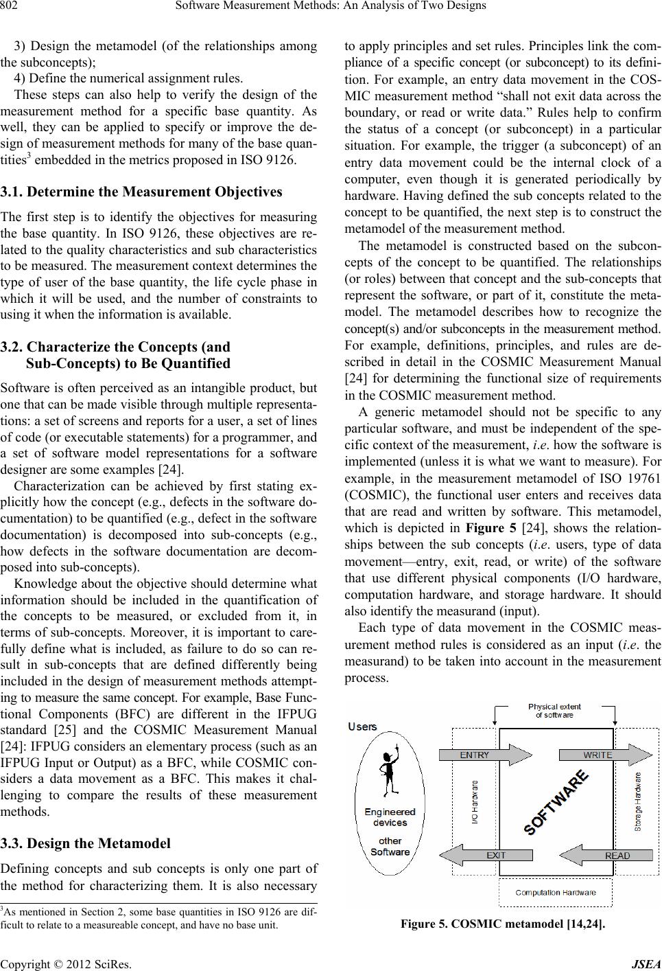 Software Measurement Methods: An Analysis of Two Designs 802 3) Design the metamodel (of the relationships among the subconcepts); 4) Define the numerical assignment rules. These steps can also help to verify the design of the measurement method for a specific base quantity. As well, they can be applied to specify or improve the de- sign of measurement methods for many of the base quan- tities3 embedded in the metrics proposed in ISO 9126. 3.1. Determine the Measurement Objectives The first step is to identify the objectives for measuring the base quantity. In ISO 9126, these objectives are re- lated to the quality characteristics and sub characteristics to be measured. The measurement context determines the type of user of the base quantity, the life cycle phase in which it will be used, and the number of constraints to using it when the information is available. 3.2. Characterize the Concepts (and Sub-Concepts) to Be Quantified Software is often perceived as an intangible product, but one that can be made visible through multiple representa- tions: a set of screens and reports for a user, a set of lines of code (or executable statements) for a programmer, and a set of software model representations for a software designer are some examples [24]. Characterization can be achieved by first stating ex- plicitly how the concept (e.g., defects in the software do- cumentation) to be quantified (e.g., defect in the software documentation) is decomposed into sub-concepts (e.g., how defects in the software documentation are decom- posed into sub-concepts). Knowledge about the objective should determine what information should be included in the quantification of the concepts to be measured, or excluded from it, in terms of sub-concepts. Moreover, it is important to care- fully define what is included, as failure to do so can re- sult in sub-concepts that are defined differently being included in the design of measurement methods attempt- ing to measure the same concept. For example, Base Func- tional Components (BFC) are different in the IFPUG standard [25] and the COSMIC Measurement Manual [24]: IFPUG considers an elementary process (such as an IFPUG Input or Output) as a BFC, while COSMIC con- siders a data movement as a BFC. This makes it chal- lenging to compare the results of these measurement methods. 3.3. Design the Metamodel Defining concepts and sub concepts is only one part of the method for characterizing them. It is also necessary to apply principles and set rules. Principles link the com- pliance of a specific concept (or subconcept) to its defini- tion. For example, an entry data movement in the COS- MIC measurement method “shall not exit data across the boundary, or read or write data.” Rules help to confirm the status of a concept (or subconcept) in a particular situation. For example, the trigger (a subconcept) of an entry data movement could be the internal clock of a computer, even though it is generated periodically by hardware. Having defined the sub concepts related to the concept to be quantified, the next step is to construct the metamodel of the measurement method. The metamodel is constructed based on the subcon- cepts of the concept to be quantified. The relationships (or roles) between that concept and the sub-concepts that represent the software, or part of it, constitute the meta- model. The metamodel describes how to recognize the concept(s) and/or subconcepts in the measurement method. For example, definitions, principles, and rules are de- scribed in detail in the COSMIC Measurement Manual [24] for determining the functional size of requirements in the COSMIC measurement method. A generic metamodel should not be specific to any particular software, and must be independent of the spe- cific context of the measurement, i.e. how the software is implemented (unless it is what we want to measure). For example, in the measurement metamodel of ISO 19761 (COSMIC), the functional user enters and receives data that are read and written by software. This metamodel, which is depicted in Figure 5 [24], shows the relation- ships between the sub concepts (i.e. users, type of data movement—entry, exit, read, or write) of the software that use different physical components (I/O hardware, computation hardware, and storage hardware. It should also identify the measurand (input). Each type of data movement in the COSMIC meas- urement method rules is considered as an input (i.e. the measurand) to be taken into account in the measurement process. 3As mentioned in Section 2, some base quantities in ISO 9126 are dif- ficult to relate to a measureable concept, and have no base unit. Figure 5. COSMIC metamodel [14,24]. Copyright © 2012 SciRes. JSEA 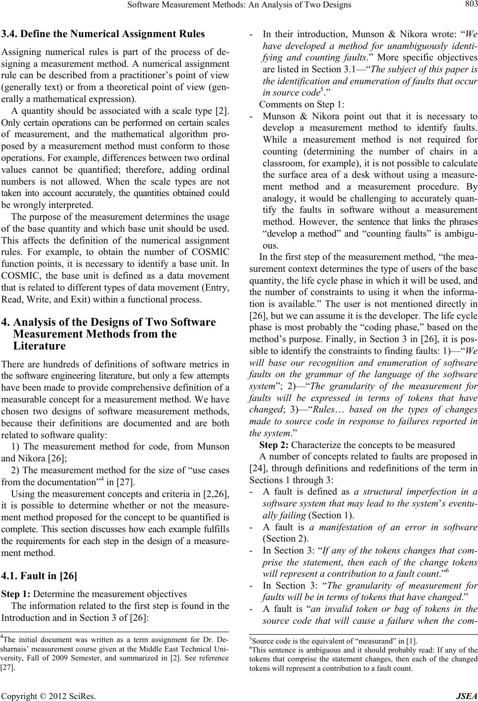 Software Measurement Methods: An Analysis of Two Designs 803 3.4. Define the Numerical Assignment Rules Assigning numerical rules is part of the process of de- signing a measurement method. A numerical assignment rule can be described from a practitioner’s point of view (generally text) or from a theoretical point of view (gen- erally a mathematical expression). A quantity should be associated with a scale type [2]. Only certain operations can be performed on certain scales of measurement, and the mathematical algorithm pro- posed by a measurement method must conform to those operations. For example, differences between two ordinal values cannot be quantified; therefore, adding ordinal numbers is not allowed. When the scale types are not taken into account accurately, the quantities obtained could be wrongly interpreted. The purpose of the measurement determines the usage of the base quantity and which base unit should be used. This affects the definition of the numerical assignment rules. For example, to obtain the number of COSMIC function points, it is necessary to identify a base unit. In COSMIC, the base unit is defined as a data movement that is related to different types of data movement (Entry, Read, Write, and Exit) within a functional process. 4. Analysis of the Designs of Two Software Measurement Methods from the Literature There are hundreds of definitions of software metrics in the software engineering literature, but only a few attempts have been made to provide comprehensive definition of a measurable concept for a measurement method. We have chosen two designs of software measurement methods, because their definitions are documented and are both related to software quality: 1) The measurement method for code, from Munson and Nikora [26]; 2) The measurement method for the size of “use cases from the documentation”4 in [27]. Using the measurement concepts and criteria in [2,26], it is possible to determine whether or not the measure- ment method proposed for the concept to be quantified is complete. This section discusses how each example fulfills the requirements for each step in the design of a measure- ment method. 4.1. Fault in [26] Step 1: Determine the measurement objectives The information related to the first step is found in the Introduction and in Section 3 of [26]: - In their introduction, Munson & Nikora wrote: “We have developed a method for unambiguously identi- fying and counting faults.” More specific objectives are listed in Section 3.1—“The subject of this paper is the identificatio n and en umera tion o f fau lts tha t oc cur in source code5.” Comments on Step 1: - Munson & Nikora point out that it is necessary to develop a measurement method to identify faults. While a measurement method is not required for counting (determining the number of chairs in a classroom, for example), it is not possible to calculate the surface area of a desk without using a measure- ment method and a measurement procedure. By analogy, it would be challenging to accurately quan- tify the faults in software without a measurement method. However, the sentence that links the phrases “develop a method” and “counting faults” is ambigu- ous. In the first step of the measurement method, “the mea- surement context determines the type of users of the base quantity, the life cycle phase in which it will be used, and the number of constraints to using it when the informa- tion is available.” The user is not mentioned directly in [26], but we can assume it is the developer. The life cycle phase is most probably the “coding phase,” based on the method’s purpose. Finally, in Section 3 in [26], it is pos- sible to identify the constraints to finding faults: 1)—“We will base our recognition and enumeration of software faults on the grammar of the language of the software system”; 2)—“The granularity of the measurement for faults will be expressed in terms of tokens that have changed; 3)—“Rules… based on the types of changes made to source code in response to failures reported in the system.” Step 2: Characterize the concepts to be measured A number of concepts related to faults are proposed in [24], through definitions and redefinitions of the term in Sections 1 through 3: - A fault is defined as a structural imperfection in a software system that may lead to the system’s eventu- ally failing (Section 1). - A fault is a manifestation of an error in software (Section 2). - In Section 3: “If any of the tokens changes that com- prise the statement, then each of the change tokens will represent a contribu tion to a fault count.”6 - In Section 3: “The granularity of measurement for faults will be in terms of tokens that have changed.” - A fault is “an invalid token or bag of tokens in the source code that will cause a failure when the com- 4The initial document was written as a term assignment for Dr. De- sharnais’ measurement course given at the Middle East Technical Uni- versity, Fall of 2009 Semester, and summarized in [2]. See reference [27]. 5Source code is the equivalent of “measurand” in [1]. 6This sentence is ambiguous and it should probably read: If any of the tokens that comprise the statement changes, then each of the changed tokens will represent a contribution to a fault count. Copyright © 2012 SciRes. JSEA 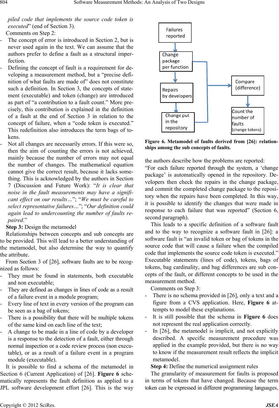 Software Measurement Methods: An Analysis of Two Designs 804 piled code that implements the source code token is executed” (end of Section 3). Comments on Step 2: - The concept of error is introduced in Section 2, but is never used again in the text. We can assume that the authors prefer to define a fault as a structural imper- fection. - Defining the concept of fault is a requirement for de- veloping a measurement method, but a “precise defi- nition of what faults are made of” does not constitute such a definition. In Section 3, the concepts of state- ment (executable) and token (change) are introduced as part of “a contribution to a fault count.” More pre- cisely, this contribution is explained in the definition of a fault at the end of Section 3 in relation to the concept of failure, when a “code token is executed.” This redefinition also introduces the term bags of to- kens. - Not all changes are necessarily errors. If this were so, then the aim of counting the errors is not achieved, mainly because the number of errors may not equal the number of changes. The mathematical equation cannot give the correct result, because it lacks some- thing. This is acknowledged by the authors in Section 7 (Discussion and Future Work): “It is clear that noise in the fault measurements may have a signifi- cant effect on our results…”; “We must be careful to se lec t representative failures…”; “Our definition could again lead to undercounting the number of faults re- paired.” Step 3: Design the metamodel Relationships between concepts and sub concepts are to be provided. This will lead to a better understanding of the metamodel, but also determine the way to quantify the attribute. From Section 3 of [26], software faults are to be recog- nized as follows: - They must be found in statements, both executable and non executable; - They are defined as changes in lines of code as a result of a failure event in a module program; - Every line of text in every version of the program can be seen as a bag of tokens; - There is a possibility that there will be multiple tokens of the same kind on each line of the text; - A change to be made in a line of code by a developer is a response to the detection of a fault, either through normal inspection or a code review process (non execu- table), or as a result of a failure event in a program module (executable). It is possible to find a schema of the metamodel in Section 6 (Current Application) of [26]. Figure 6 sche- matically represents the fault definition as applied to a JPL software development effort [26]. This is the way Figure 6. Metamodel of faults derived from [26]: relation- ships among the sub concepts of faults. the authors describe how the problems are reported: “For each failure reported through the system, a ‘change package’ is automatically opened in the repository. De- velopers then check the repairs in the change package, and commit the completed change package to the reposi- tory when the repairs have been completed. In this way, it is possible to identify the changes that were made in response to each failure that was reported” (Section 6, second paragraph). This leads to a specific definition of a software fault and to the way to recognize a software fault in [26]: a software fault is “an invalid token or bag of tokens in the source code that will cause a failure when the compiled code that implements the source code token is executed.” Executable statements (lines of code), tokens, bags of tokens, bag cardinality, and bag differences are sub con- cepts of the fault, or different concepts to be used in the measurement method. Comments on Step 3: - There is no schema provided in [26], only a text and a figure from a CVS application. Here, Figure 6 at- tempts to model these explanations. - It is still possible that the schema in Figure 6 does not represent the real application correctly. - In [26], the metamodel is implicit, and not explicitly described. A specific measurement procedure was applied in the example provided, but there is no way to know if the measurement result reflects the implicit metamodel. Step 4: Define the numerical assignment rules The granularity of measurement for faults is proposed in terms of tokens that have changed. Because the term token can be expressed in different programming languages, Copyright © 2012 SciRes. JSEA  Software Measurement Methods: An Analysis of Two Designs 805 Table 2. The token change concept. 1) a = b + c; (5 tokens) 2) a = b – c; (5 tokens) Need to change + by – 1 token change its definition remains a part of the measurement method. As observed in Table 2, the concept of change in [26] is related to the number of tokens changed in a statement. A, =, b, +, c are tokens of statement 1. The only change in statement 2 is the token +, which is replaced by the token. The measurement method described in [26] has the following assignment rules to obtain the number of soft- ware faults: - A unit of measurement is assigned to every token change in the code; - To obtain the number of faults, the measurer adds up the token changes; - Actually, one changed token constitutes one unit; - There is a measurement rule for adding each change automatically. The example in [26] is related to the C programming language; - As each token change is expressed as one unit, the result of adding token changes can be considered as a ratio scale type. Comments on Step 4: There is room for improvement to the measurement method proposed in [26], as follows: - Identify the base unit: the token; - Impose a rule to obtain the number of faults (token changes), the clear choice being: add up the token changes; - Complete the set of rules for finding a fault, which is currently incomplete. For example: if a = 1 + c + b is changed to a = 1 + b + c, how many faults should be counted, considering that the user sees no change in the results (i.e. there is no failure). The proposal in [26] constitutes one of the rare efforts to propose a measurement method related to the quality of software. However, based on the previous comments, the metamodel and the measurement rules can be improved. 4.2. Use Case (Ozcan Top) This sizing of use cases as an example of the design of a base measure can be found in [27] [2, ch. 4, pp. 87-91]. Step 1: Determine the measurement objectives In the Measurement Objective section, the author states: “The aim of this measurement method is to measure the size of the case.” Again, “the results of this measurement will also be helpful in assessing the internal quality, ex- ternal quality, and quality-in-u se of a software product.” Finally, the measurement method “can be used by soft- ware developers, software managers, and customers.” [27] The results of the measurement can even be applied in the early phases of a software life cycle, i.e. when use case requirements are available. Comment on Step 1: - The measurement objectives are clearly formulated. Step 2: Characterize the concepts to be measured The measurable concept is size, but size is related to the use cases. So, because use cases are related to require- ments, size is an indirect quantification of the requirements. A use case is “the description of the interaction be- tween an Actor (the initiator of the interaction) and the system itself. It is represented as a sequence of simple steps. Each use case is a complete series of events, de- scribed from the point of view of the Actor. Actor, Main Scenario, Alternative Path s (Extensions), and Exceptions are the concepts of the measurement method” [27]. - The author has defined the various “events” in Table 3; - The subconcepts are input, process, and output; - The input is “any item, whether internal or external to the project, that is required by a process before that process procee ds .” - The output is the “data transmitted to an external destination” or “a product, result, or service generated by a process.” - The process is “a set of interrelated or interacting activities which tran sforms inputs into outputs.” The author presents the various event types from a use case template: Table 3. Use case template [27]. Use case ID Use case name Creator Creation date Modifier Modification date GUI Flow diagram Actor Description Pre-conditions Post-conditions Priority Frequency of use Main scenario 1. 2. 3. Alternative paths Exceptions Inclusions Notes and issues Copyright © 2012 SciRes. JSEA 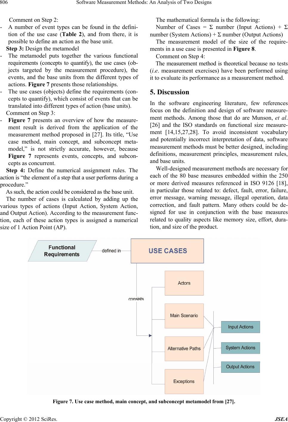 Software Measurement Methods: An Analysis of Two Designs Copyright © 2012 SciRes. JSEA 806 The mathematical formula is the following: Comment on Step 2: - A number of event types can be found in the defini- tion of the use case (Table 2), and from there, it is possible to define an action as the base unit. Step 3: Design the metamodel Number of Cases = Σ number (Input Actions) + Σ number (System Actions) + Σ number (Output Actions) The measurement model of the size of the require- ments in a use case is presented in Figure 8. - The metamodel puts together the various functional requirements (concepts to quantify), the use cases (ob- jects targeted by the measurement procedure), the events, and the base units from the different types of actions. Figure 7 presents those relationships. Comment on Step 4: The measurement method is theoretical because no tests (i.e. measurement exercises) have been performed using it to evaluate its performance as a measurement method. 5. Discussion - The use cases (objects) define the requirements (con- cepts to quantify), which consist of events that can be translated into different types of action (base units). Comment on Step 3: In the software engineering literature, few references focus on the definition and design of software measure- ment methods. Among those that do are Munson, et al. [26] and the ISO standards on functional size measure- ment [14,15,27,28]. To avoid inconsistent vocabulary and potentially incorrect interpretation of data, software measurement methods must be better designed, including definitions, measurement principles, measurement rules, and base units. - Figure 7 presents an overview of how the measure- ment result is derived from the application of the measurement method proposed in [27]. Its title, “Use case method, main concept, and subconcept meta- model,” is not strictly accurate, however, because Figure 7 represents events, concepts, and subcon- cepts as concurrent. Step 4: Define the numerical assignment rules. The action is “the element of a step that a user performs during a procedure.” Well-designed measurement methods are necessary for each of the 80 base measures embedded within the 250 or more derived measures referenced in ISO 9126 [18], in particular those related to: defect, fault, error, failure, error message, warning message, illegal operation, data correction, and fault pattern. Many others could be de- signed for use in conjunction with the base measures related to quality aspects like memory size, effort, dura- tion, and size of the product. As such, the action could be considered as the base unit. The number of cases is calculated by adding up the various types of actions (Input Action, System Action, and Output Action). According to the measurement func- tion, each of these action types is assigned a numerical size of 1 Action Point (AP). Figure 7. Use case method, main concept, and subconcept metamodel from [27]. 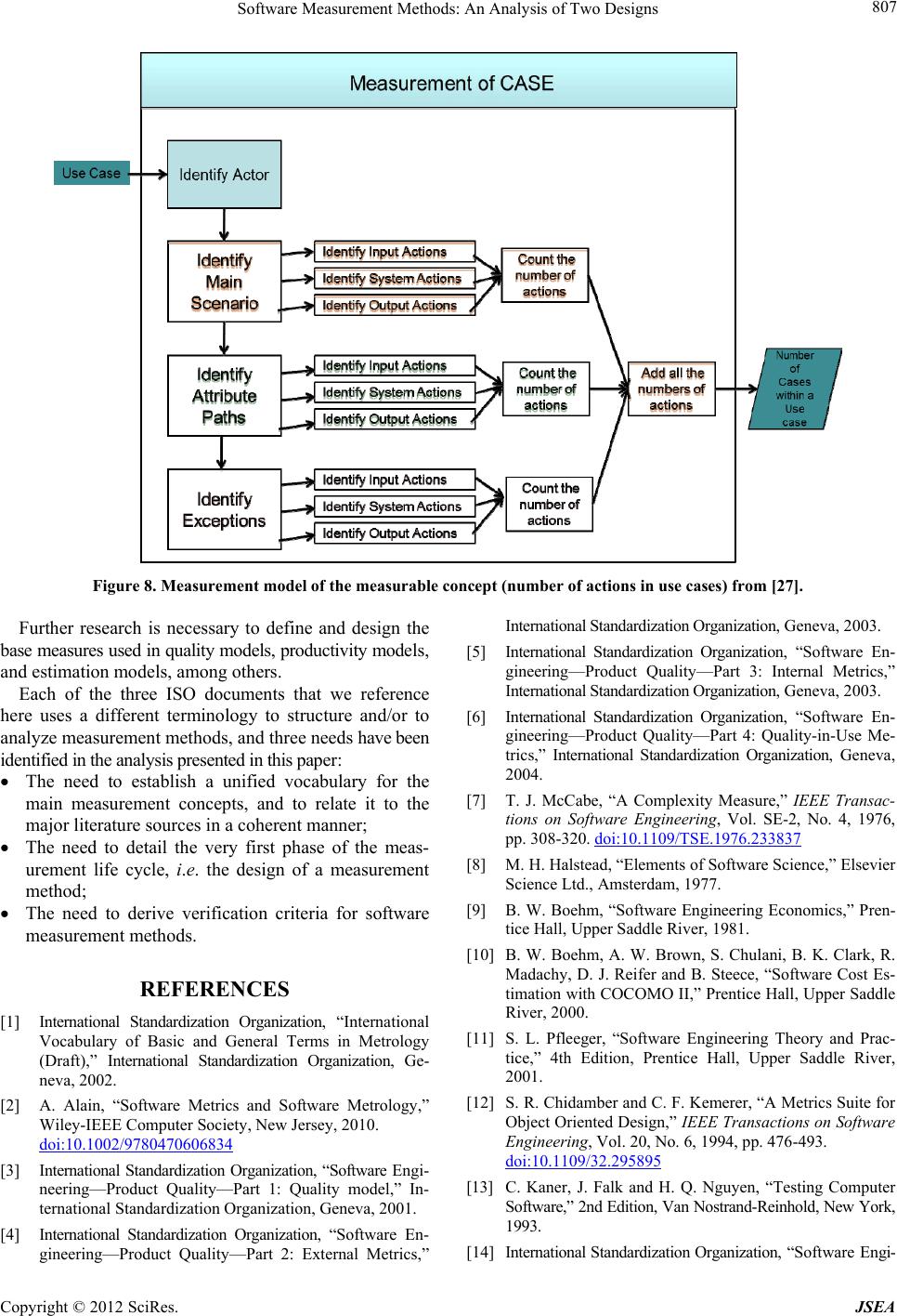 Software Measurement Methods: An Analysis of Two Designs 807 Figure 8. Measurement model of the measurable concept (number of actions in use cases) from [27]. Further research is necessary to define and design the base measures used in quality models, productivity models, and estimation models, among others. Each of the three ISO documents that we reference here uses a different terminology to structure and/or to analyze measurement methods, and three needs have been identified in the analysis presented in this paper: The need to establish a unified vocabulary for the main measurement concepts, and to relate it to the major literature sources in a coherent manner; The need to detail the very first phase of the meas- urement life cycle, i.e. the design of a measurement method; The need to derive verification criteria for software measurement methods. REFERENCES [1] International Standardization Organization, “International Vocabulary of Basic and General Terms in Metrology (Draft),” International Standardization Organization, Ge- neva, 2002. [2] A. Alain, “Software Metrics and Software Metrology,” Wiley-IEEE Computer Society, New Jersey, 2010. doi:10.1002/9780470606834 [3] International Standardization Organization, “Software Engi- neering—Product Quality—Part 1: Quality model,” In- ternational Standardization Organization, Geneva, 2001. [4] International Standardization Organization, “Software En- gineering—Product Quality—Part 2: External Metrics,” International Standardization Organization, Geneva, 2003. [5] International Standardization Organization, “Software En- gineering—Product Quality—Part 3: Internal Metrics,” International Standardization Organization, Geneva, 2003. [6] International Standardization Organization, “Software En- gineering—Product Quality—Part 4: Quality-in-Use Me- trics,” International Standardization Organization, Geneva, 2004. [7] T. J. McCabe, “A Complexity Measure,” IEEE Transac- tions on Software Engineering, Vol. SE-2, No. 4, 1976, pp. 308-320. doi:10.1109/TSE.1976.233837 [8] M. H. Halstead, “Elements of Software Science,” Elsevier Science Ltd., Amsterdam, 1977. [9] B. W. Boehm, “Software Engineering Economics,” Pren- tice Hall, Upper Saddle River, 1981. [10] B. W. Boehm, A. W. Brown, S. Chulani, B. K. Clark, R. Madachy, D. J. Reifer and B. Steece, “Software Cost Es- timation with COCOMO II,” Prentice Hall, Upper Saddle River, 2000. [11] S. L. Pfleeger, “Software Engineering Theory and Prac- tice,” 4th Edition, Prentice Hall, Upper Saddle River, 2001. [12] S. R. Chidamber and C. F. Kemerer, “A Metrics Suite for Object Oriented Design,” IEEE Transactions on Software Engineering, Vol. 20, No. 6, 1994, pp. 476-493. doi:10.1109/32.295895 [13] C. Kaner, J. Falk and H. Q. Nguyen, “Testing Computer Software,” 2nd Edition, Van Nostrand-Reinhold, New York, 1993. [14] International Standardization Organization, “Software Engi- Copyright © 2012 SciRes. JSEA  Software Measurement Methods: An Analysis of Two Designs 808 neering—COSMIC—A Functional Size Measurement Me- thod,” International Standardization Organization, Geneva, 2010. [15] International Standardization Organization, “Information Technology—Software Measurement—Functional Size Measurement—Definition of Concepts,” International Standardization Organization, Geneva, 2007. [16] International Standardization Organization, “Systems and Software Engineering—Measurement Process,” Interna- tional Standardization Organization, Geneva, 2007. [17] International Standardization Organization, “System and Software Engineering—System and Software Quality Requirements and Evaluation (SQuaRE)—System and Software Quality Models,” International Standardization Organization, Geneva, 2010. [18] J. M. Desharnais, A. Abran and W. Suryn, “Attributes and Related ISO 9126: A Pareto Analysis, Software Quality Management,” British Computer Society, London, 2009. [19] International Standardization Organization, “Systems and Software Engineering—Vocabulary, Final Draft,” Inter- national Standardization Organization, Geneva, 2009. [20] International Standardization Organization, “Systems and Software Engineering—Systems and Software Quality Requirements and Evaluation (SQuaRE)—Quality Meas- ure Elements,” International Standardization Organization, Geneva, 2012. [21] L. Carnahan, G. Carver, M. Gray, M. Hogan, T. Hopp, J. Horlick, G. Lyon and E. Messina, “Metrology for Infor- mation Technology, Public Report Number A853084,” National Institute of Standards and Technology, Gai- thersburg, 1997. [22] M. M. Gray, “Application of Metrology to Information Technology,” Journal of Research of the National Insti- tute of Standards and Technology, Vol. 104, No. 6, 1999, pp. 567-578. doi:10.6028/jres.104.035 [23] N. Habra, A. Abran, M. Lopez and A. Sellami, “A Framework for the Design and Verification of Software Measurement Methods,” Journal of Systems and Software, Vol. 81, No. 5, 2008, pp. 633-648. doi:10.1016/j.jss.2007.07.038 [24] COSMIC Group, “COSMIC Measurement Method, Ver- sion 3.0.1, Measurement Manual,” The COSMIC Imple- mentation Guide for ISO/IEC 19761, 2003, 2008. http://www.cosmicon.com/dl_manager4.asp?id=73 [25] International Standardization Organization, “Software En- gineering—NESMA Functional Size Measurement Method Version 2.1—Definitions and Counting Guidelines for the Application of Function Point Analysis,” International Standardization Organization, Geneva, 2005. [26] J. C. Munson and A. P. Nikora, “Toward a Quantifiable Definition of Software Faults,” Proceedings of the 13th International Symposium on Software Reliability Engi- neering, Washington, 12-15 November 2002, p. 388. doi:10.1109/ISSRE.2002.1173299 [27] O. O. Top, “Measurement Method for Case, SM517 Software Measure,” Middle East Technical University, Ankara, 2009. [28] International Standardization Organization, “Software En- gineering—IFPUG 4.1 Unadjusted Functional Size Mea- surement Method—Counting Practices Manual,” Interna- tional Standardization Organization, Geneva, 2009. [29] International Standardization Organization, “Software En- gineering—Mk II Function Point Analysis—Counting Practices Manual,” International Standardization Organiza- tion, Geneva, 2002. [30] A. Abran, R. E. Al-Qutaish, J. M. Desharnais and N. Habra, “An Information Model for Software Quality Measurement with ISO Standards,” International Con- ference on Software Development—SWEDC-REK, Reyk- javik, 13-16 July 2005, pp. 104-116. [31] R. E. Al-Qutaish, “SPQMM: A Software Product Quality Maturity Model Using ISO/IEEE Standards, Metrology, and Sigma Concepts,” Ph.D. Thesis, Université du Qué- bec, Montréal, 2007. [32] A. Abran, R. E. Al-Qutaish and J. M. Desharnais, “Har- monization Issues in the Updating of the ISO Standards on Software Product Quality,” Metrics News, Vol. 10, No. 2, 2005, pp. 35-44. Copyright © 2012 SciRes. JSEA 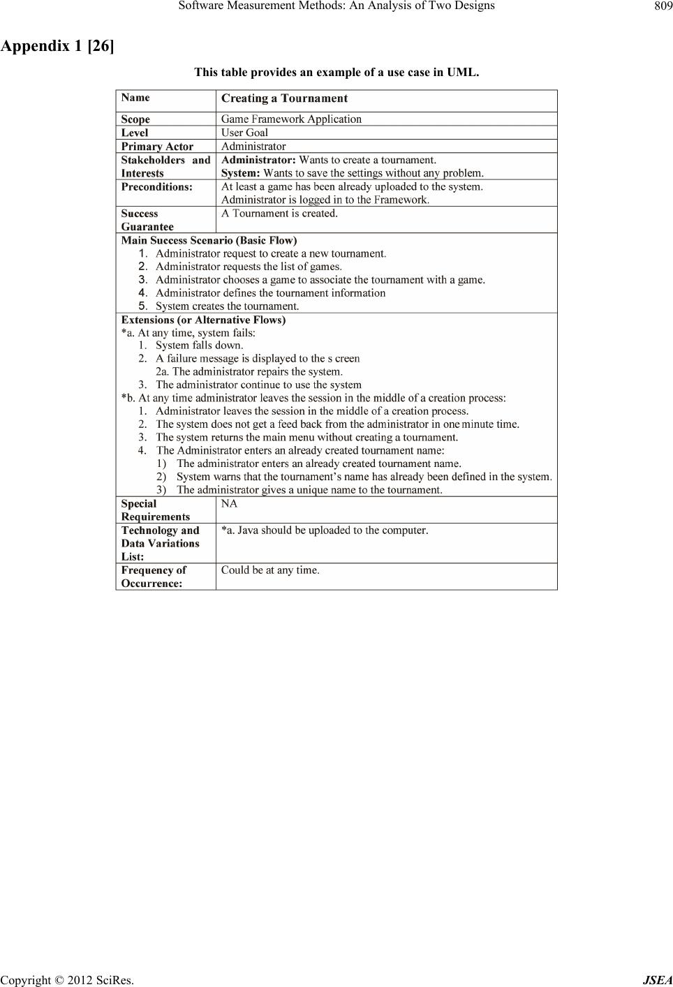 Software Measurement Methods: An Analysis of Two Designs 809 Appendix 1 [26] This table provides an example of a use case in UML. Copyright © 2012 SciRes. JSEA
|