 Journal of Modern Physics, 2012, 3, 1639-1646 http://dx.doi.org/10.4236/jmp.2012.330201 Published Online October 2012 (http://www.SciRP.org/journal/jmp) Radial Electric Field in Tokamak Plasmas as a Physical Consequence of Ehrenfest’s Paradox Alexander Romannikov ITER Domestic Agency—“ITER Project Center”, 123182, pl. Academician Kurchatov, 1, p. 3, Moscow, Russia Email: a.romannikov @ iterrf.ru Received August 28, 2012; revised September 27, 2012; accepted October 3, 2012 ABSTRACT A simplified form and some possible theoretical resolutions of the so-called Ehrenfest’s Paradox are described. A rela- tion between physical consequences of this relativistic paradox and charge density ρ of tokamak plasma is shown. Plasma experiments which could resolve the Ehrenfest’s Paradox are presented. Keywords: Tokamak; Ehrenfest’s Paradox 1. Introduction Ehrenfest’s Paradox was presented in [1] for the first time in 1909. Detailed historical, physical, and geomet- rical descriptions of Ehrenfest’s Paradox can be found in [2] and references therein. For our experimental purposes, let’s present Ehrenfest’s Paradox in the following simpli- fied form. Consider two thin rings with radii 1 and 2 (and 12 ). The second ring is accelerated by an external force so that any point on the ring has linear velocity . The observers in the laboratory frame measure circumferences of these rings (1 and 2) and radii. The question is: what are the results of these mea- surements taking into account relativistic effects? R RR V L L R L R The analysis of relativistic contraction and of related effects in non-inertial rotating frame (including geomet- rical arguments, purely kinematical and dynamical grounds) is very complex. But physical consequences of these complex analyses are sufficiently simple. We can basically present three possible theoretical hypotheses for the results of circumference measurements. The first hypothesis, which is not widely accepted, will only be mentioned here. Pursuant to this hypothesis, both the radius of the rotating ring 2 and its circum- ference 2 contract in the laboratory frame by relativis- tic effects, so that their ratio remains equal 21 21 2π LL RR 12 1122 and 2π2πRR L R RL LR 2π [3,4]. From the contemporary point of view, this resolution of the Ehrenfest’s Paradox is highly unlikely see, for example [2]. For most researchers, a more acceptable resolution to Ehrenfest’s Paradox in the laboratory frame is as follows: (1) We shall refer to it as “hypothesis 1”. Though the nu- ances of “hypothesis 1” are not so important for our dis- cussion, we will consider this hypothesis in more detail. There are two possible ways to obtain this result. Let’s introduce the circumference and radius 2 of a rotating ring in the rotating reference frame (with the linear velocity at the radius ). V R 122 LLL 2 The first and less accepted approach is based on the assumption of “no Lorentz contraction for rotating refer- ence frame” [5-8]. This would mean that RRR and 122 . The second and more widespread approach is based, in a simplified form, on the following ideas. According to [9], 22 2 2 1 1 LLL V c 22 RR LL , and . We shall refer to it as “condition (1)”. The authors (see, for exam- ple, [10-16]), through the analysis of a metric tensor for a rotating reference frame, have come to the following conclusion. The condition (1) is fulfilled but the rotating observers would see the increase of the circumference in the form of 1 11 LL LL . The laboratory observers would see a relativistic contraction of a rotating ring in the form of 21 1 R 2πLR , and 122 RR . It is important to emphasize that the majority of the advo- cated of the standard resolution of the Ehrenfest’s Para- dox a priori believe that the geometry of the rotated ring in the laboratory inertial frame is Euclidean, 22 , and they analyze mainly the geometry of the rotating ring in the rotating frame. Let’s follow the foregoing logic of the more wide- spread approach, but assume that the circumference measured by the observers in the rotating reference frame C opyright © 2012 SciRes. JMP  A. ROMANNIKOV 1640 does not change due to the rotation and is equal to the initial length of the non-rotating ring 1 (see, for exam- ple, [17-19]). Then, the laboratory observers would con- clude that: L 122 RRR Vr r a 1 21 andLL (2) We shall use the Equation (2) refer to it as “the hy- pothesis 2”. It is necessary to emphasize, that in the case of “hypothesis 2” the geometry of the rotating ring in the laboratory frame is Non-Euclidean. Unfortunately, it is practically impossible to resolve the Ehrenfest’s Paradox by observing the real rotating disks or rings because of centrifugal forces that lead to significant deformation of the rings. Thus, it is difficult to measure very small relativistic effects against the background of the centrifugal deformation at accessible rotation velocities and size of rings. Note that the first experimental studies of the measurement of physical consequences of the Ehrenfest’s Paradox were presented only in [19], 2011. 2. Physical Consequences of the Ehrenfest’s Paradox in Tokamak Plasma Recently, in [19,20] the effect of relativistic contraction of an “electron ring” circumference in steady state toka- mak plasma rotating in toroidal direction with current velocity e has been analyzed. Let be the minor radius of a tokamak magnetic surface, see Figure 1. The minor tokamak radius was assumed to be much less than the major radius , where R1 a R = Vr , and electron toroidal rotation velocity was assumed to be moderate, so that it would be possible to exclude centrifugal forces in the momentum balance of plasma [21]. The toroidal rota- tion velocity of “the ion ring” i, as a general rule, is much less than the toroidal rotation velocity of the “elec- tron ring”, a fact known from experiment [21]. It is as- sumed that at the moment of plasma creation (with no current) from neutral gas (hydrogen or deuterium), the electron density and the ion density 0 e nr 0 i nr are Figure 1. A sketch of tokamak. equal, and the difference between the total number of electrons and total number of ions does not vary during a discharge and is equal to 0 in the tokamak chamber. We can use the last assumption because neutral gas is in- jected into the tokamak chamber, and neutral gas is pumped from the tokamak. Electrons and ions can move and can be redistributed in the minor radius direction of tokamak plasma after the occurrence of a current. One can note that the peak value of the experimentally measured radial electric field r in tokamak coin- cides with the occurrence in plasma a small difference between electron density e and ion density Er nr i nr in the laboratory frame [19,20], of the order of max 2 ie e e nr nrVr nr c ; and for the ohmic modes: 2 ie i e nr nrVr nr c r 0 n0 n00 nn 2π electron ion LRL V VV = . We shall refer to it as “con- dition (2)”. Let us assume at the beginning, that the total number of electrons and ions does not vary during a discharge, electron density and ion density, ion toroidal rotation velocity and electron rotation velocity values are constant and do not depend on the tokamak minor radius . In this case, initial electron density (before plasma current) is and ion density is , where . ei ei Therefore, this can be considered as two thin rings (the electron ring and the ion ring), originally having the same circumference , which are brought to different toroidal rotation velocities, e and i, where ie V. The situation is similar to the one considered above in the context of Ehrenfest’s Paradox. Following the ideas summarized by E. L. Feinberg in [22], it is not necessary to investigate in detail the proc- ess of electron ring and ion ring acceleration to given velocities. One can compare only an initial and a final states. In this case, measurement of the part of the elec- tric field which can arise, for example, within the frame of “the hypothesis 2”, is much easier than the investiga- tion of the deformations of a rotating rigid ring. The rea- son is as follows: on one hand, the current electron ve- locity can reach hundreds km/s, on the other hand, possi- ble deformations of the “electron ring” due to centrifugal force will lead only to the occurrence of dipole compo- nents in the electric field associated with minor change of radius of the rotating ring. Relativistic contraction of the ring circumference without change of radius and conser- vation of total electron number (under the “the hypothe- sis 2”) can lead to the occurrence of a monopole compo- nent in electric field which is relatively easy to measure, as it will be shown below. Following [19], let us consider the change in density of charges in tokamak plasma under “hypothesis 1” Copyright © 2012 SciRes. JMP  A. ROMANNIKOV 1641 and “hypothesis 2”. “Hypothesis 1” It is obvious from Equation (1) that tokamak charge density is not changed after the appearance of the toroidal rotating electron (current) ring and ion ring in plasma, that is: 0 (3) “Hypothesis 2” Following [19], it is possible to show that in this case rotation creates a finite charge density in a tokamak plasma.. If we ignore higher-order terms in 2 2 V c expan- sion, we can write: 22 22 2 2 2 22 11 11 11 22 2 2 ie ie ie eie e ie i e en en VV cc en en enV Ven cen en n jV j cen c 22 22 2 ie eie i VV cc V VV c nn V (4) where e and i are: the electron density in the rotat- ing frame with velocity e V and the ion density in the rotating frame with the velocity i, respectively. We have taken into account the framework of “hypothesis 2”: 22 22 11 ion i V Lc 00 ei nnn electron electronion e rot rot V LL L c and e e Change of the charge density in this case is only asso- ciated with relativistic change of the denominator in the expression for the density. Let us note that n. depends on parameters measured in the laboratory frame: the cur- rent density , the electron density and the ion tor- oidal rotation velocity . je n i So, we have calculated the charge density V in each point inside a stationary tokamak chamber in the labora- tory frame. One can “forget” about the particular nature of the charge density relating to the Non-Euclidean geometry of a rotating electron (ion) ring of the tokamak plasma in the laboratory frame, and can instead use the Poisson equation (being the relativity theory equation in the laboratory frame) with taken from Equation (4) to calculate the electrostatic radial electric field in toka- mak plasma. Hence, r in a simple tokamak plasma is created by two relativistic terms in the density of charges Er , Equation (4), which appeared in the labora- tory frame. In case of a real tokamak, plasma parameters depend on the minor radius of magnetic surfaces. Consideration of such dependence for the purpose of calculation of to- kamak plasma charge density is shown in [19,20] in de- tail for 1 a R =. The principal point here is the consid- eration of each nested magnetic surface with plasma dis- tributed in a thin, hollow ring. Following [19], we can rewrite Equation (3) in the case of “hypothesis 1” so as to take into account the processes of redistribution of electrons and ions on the minor radius by plasma diffusion (convection): dd ie renr nr (5) Due to electron and ion diffusion (change of the nu- merator in the expression for the density), additional volume charge densities in plasma can arise, and this can be expressed by the term dd en rn r ie in (5). Hence, only the diffusion (convection) of ions and elec- trons could create Er r In the case of “hypothesis 2”, we can rewrite the Equation (4) in the following form: in tokamak plasma. 2 22 2 i e dd ie jr jrVr rcenr c en rn r (6) where eie jenrVrVr . Equation (6) has two relativistic terms, and “condition (2)” is not merely casual coincidence in this case. Let us emphasize again that r depends on the plasma pa- rameters measured in the laboratory frame: the current density jr nr, the electron density e, the ion tor- oidal rotation velocity Vr i and the diffusion (convec- tion) term. So, we have calculated the charge density in each point inside a stationary tokamak chamber in the laboratory frame, Equation (6). As emphasized above, one can “forget” about the particular nature of the charge density relating partially to the Non-Euclidean ge- ometry of a rotating electron (ion) ring of the tokamak plasma in the laboratory frame, and can use the Poisson equation with taken from Equation (6) to calculate the electrostatic radial electric field in the tokamak plasma. In our consideration, the diffusion (convection) term is not determined. We can mention one integral property of the diffusion (convention) term, which is a consequence of the physical assumption that the differ- ence between the total number of electrons and total number of ions does not vary during a discharge and is equal to 0 in a tokamak chamber. It is: d0 ch dd ie V en rn rV (7) Copyright © 2012 SciRes. JMP 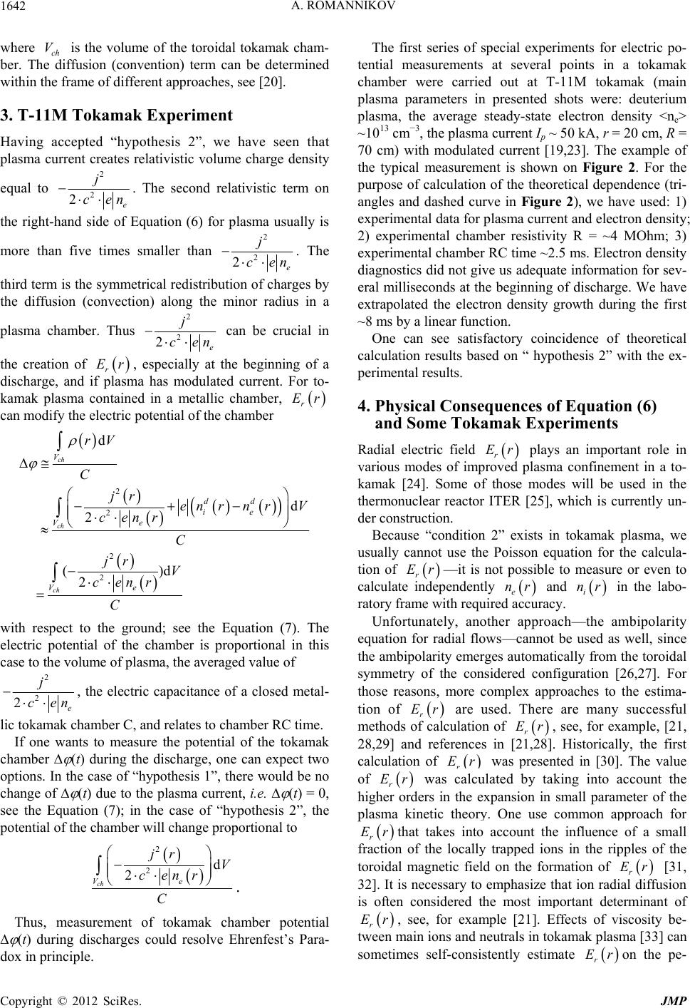 A. ROMANNIKOV 1642 where ch is the volume of the toroidal tokamak cham- ber. The diffusion (convention) term can be determined within the frame of different approaches, see [20]. V 3. T-11M Tokamak Experiment Having accepted “hypothesis 2”, we have seen that plasma current creates relativistic volume charge density equal to 2 2 2e j cen . The second relativistic term on the right-hand side of Equation (6) for plasma usually is more than five times smaller than 2 2 2e j cen . The third term is the symmetrical redistribution of charges by the diffusion (convection) along the minor radius in a plasma chamber. Thus 2 2 2e j cen Er can be crucial in the creation of r, especially at the beginning of a discharge, and if plasma has modulated current. For to- kamak plasma contained in a metallic chamber, r Er can modify the electric potential of the chamber 2 2 2 2 d 2 ()d 2 ch ch ch V Ve Ve rV C jr en r cenr C jr V cenr C d dd ie n rV with respect to the ground; see the Equation (7). The electric potential of the chamber is proportional in this case to the volume of plasma, the averaged value of 2 2 2e j cen , the electric capacitance of a closed metal- lic tokamak chamber C, and relates to chamber RC time. If one wants to measure the potential of the tokamak chamber (t) during the discharge, one can expect two options. In the case of “hypothesis 1”, there would be no change of (t) due to the plasma current, i.e. (t) = 0, see the Equation (7); in the case of “hypothesis 2”, the potential of the chamber will change proportional to 2 2 2 ch d Ve jr V cenr C . Thus, measurement of tokamak chamber potential (t) during discharges could resolve Ehrenfest’s Para- dox in principle. The first series of special experiments for electric po- tential measurements at several points in a tokamak chamber were carried out at T-11M tokamak (main plasma parameters in presented shots were: deuterium plasma, the average steady-state electron density <ne> ~1013 cm−3, the plasma current Ip ~ 50 kA, r = 20 cm, R = 70 cm) with modulated current [19,23]. The example of the typical measurement is shown on Figure 2. For the purpose of calculation of the theoretical dependence (tri- angles and dashed curve in Figure 2), we have used: 1) experimental data for plasma current and electron density; 2) experimental chamber resistivity R = ~4 MOhm; 3) experimental chamber RC time ~2.5 ms. Electron density diagnostics did not give us adequate information for sev- eral milliseconds at the beginning of discharge. We have extrapolated the electron density growth during the first ~8 ms by a linear function. One can see satisfactory coincidence of theoretical calculation results based on “ hypothesis 2” with the ex- perimental results. 4. Physical Consequences of Equation (6) and Some Tokamak Experiments Radial electric field Er r plays an important role in various modes of improved plasma confinement in a to- kamak [24]. Some of those modes will be used in the thermonuclear reactor ITER [25], which is currently un- der construction. Because “condition 2” exists in tokamak plasma, we usually cannot use the Poisson equation for the calcula- tion of Er nr i nr r—it is not possible to measure or even to calculate independently e and in the labo- ratory frame with required accuracy. Unfortunately, another approach—the ambipolarity equation for radial flows—cannot be used as well, since the ambipolarity emerges automatically from the toroidal symmetry of the considered configuration [26,27]. For those reasons, more complex approaches to the estima- tion of Er Er r are used. There are many successful methods of calculation of r, see, for example, [21, 28,29] and references in [21,28]. Historically, the first calculation of Er r was presented in [30]. The value of Er r was calculated by taking into account the higher orders in the expansion in small parameter of the plasma kinetic theory. One use common approach for Er rthat takes into account the influence of a small fraction of the locally trapped ions in the ripples of the toroidal magnetic field on the formation of Er r [31, 32]. It is necessary to emphasize that ion radial diffusion is often considered the most important determinant of Er r, see, for example [21]. Effects of viscosity be- tween main ions and neutrals in tokamak plasma [33] can sometimes self-consistently estimate on the pe- r Er Copyright © 2012 SciRes. JMP  A. ROMANNIKOV Copy2 JMP 1643 Figure 2. Time dependence of plasma current Ip(t) and the tokamak chamber electric potential (t) during the discharge, T-11M tokamak [23]. Solid curve is the experimental dependence of (t); triangles and dashed curve are the theoretical dependence. Vr p and right © 012 SciRes. riphery of the plasma. The influence of large gradients of the radial electric field on the shape of ion trajectories [34] sometimes allows qualitative explanation of some of the issues of the formation of r in modes with Er internal thermal barriers. Some authors introduce ano- malous viscosities in the standard neo-classical theory [35], etc. It is necessary to note that it is very difficult to mea- sure accurately the radial electric field profile in a toka- mak. This complexity gives rise to situations where experi- mental results concerning Er Er Er r are difficult to explain using simple approaches, see for example [36-40]. There- fore, it is often necessary to use complex contemporary theories. It will be shown below that same experimental results can be explained by enough simple approach based on Equation (6), too. Let us assume that the charge density, Equation (6), creates r in tokamak plasma. To compare the re- sults of this approach to rwith the results of some actual experiments, we take into account the additional plasma equation, see, for example, [21] (which is derived from radial equilibrium of forces on a magnetic surface): d 1 d tp i r i Pr Er ce nr pt Vr B rVr B rc (8) where t V (ti Vr in the article are the velocities of the poloidal and toroidal rotation of plasma ions, respectively, and hence, of the plasma as a whole (the velocities are low enough so the centrifugal effect may be omitted); is the speed of light, is the electron charge; r Vr ce i and are the density and pressure of plasma ions; p B and nr i Pr r Br Er t are poloidal and toroidal magnetic fields. To establish the main features of relations between r and Vr t, as well as other plasma parameters, we may ignore the weak poloidal dependence of parameters in Equation (8) (1cos r R R, where is the major radius of the to- kamak, is the poloidal angle; 1 r R = r ). A relation of type (8) is always true when the plasma is in the steady state (only these states are considered below). For the sake of simplicity, let’s assume that magnetic surfaces are nested cylinders with small radii , and the plasma consists of electrons and, for example, deuterium ions. Let’s also assume that the velocity of poloidal rotation may be taken from experiments or derived from neo- classical theory. We can express Er Vr r and t independently using Equation (6), the Poisson equation and Equation 8): (  A. ROMANNIKOV 1644 2 с j d d2 dd 11 1 d dd a pidd t rp ie pep e r ppt i pe ra Br Pj Bc ErVenn cBenBen BVrB Pr Bcenrr (9), 2 dd dd ii ra Pr r с nn j d d2 d 11 d d tt ip p pep pep a idd t pie pep er p p Pr BB cc VrV rV r Br enrBrrBr enrBr Pj Bc Ve BenB en B B ra (10) We take into account the assumption that the toroidal rotation velocity at the plasma boundary with is close to zero [41]. One can find an example of the deri- vation procedure and interpretation of equations similar to Equations (9) and (10) in [41]. Below we present important quantitative and qualita- tive correlations of theoretical results (using Equations (6), (9) and (10)) with tokamak experimental data [20,36- 42]. The first important conclusion from Equation (10): if 2 dd ie jr n 2 2e en ce nr is not close to zero in the plasma core then a toroidal ion beam is created in that region (its velocity logarithmically tending to infin- ity [20,23]). So, we have to suppose that 2 2e en ce nr 2 0 dd ie jr n at the core of the plasma. Consequently, one can write the Poisson equation for this case: 2 22 1d i jrV r rc dr rE r r and calculate the radial electric field profile: 0 rp Er B crc d 1d d r pi i BrVr V (11) where 0 4πd r jr p Br rc in the plasma periphery; and has the minimum (negative . It is possible to derive Equation (11) from Equation (9) directly, see [19]. As very good know from experiments, see, for exam- ple, [36], the radial electric field for tokamak Ohmic modes is equal zero in the plasma center; is close to zero value in several kV/m) in the middle region of the plasma. as calculated using Equation (11) is presented in Figure stigation of so-called “locked” mode is another qu r Er 3 for typical ohmic discharge in TCV tokamak [36]. One can see satisfactory agreement of theoretical calculation based on Equation (11) with experimental re- sults. Inve antitative example of this approach. In this mode, plas- ma stops rotating in the toroidal direction on all magnetic surfaces, and experimental r Er becomes close to zero Figure 3. Example of radial electric field Er(r) profile ca mental toroidal rotation plasma velocity profile. l- culation in a typical ohmic discharge in TCV tokamak [36]. is the effective radius of the tokamak magnetic surface. Solid curve is the experimental Er(r) profile; squares are the Er(r) values calculated with Equation (11) using the experi- Copyright © 2012 SciRes. JMP  A. ROMANNIKOV 1645 everywhere [37]. For example, obtaining the result 0Er with the condition that 0Vr ri is difficult to explain with approaches based only on Equation (8), but it is the trivial consequence of Equation (11). Polarity and typical values of toroidal rotation velocity in plasma cores in most ohmic modes and some modes with ICRH (if ion toroidal rotation velocity is opposite to the plasma current and is equal to 10 ÷ 100 km/s [21,39]) are correctly described by Equation (10) with 2 dd jr en n 20 2ie e cenr for real ion pressure profiles [20,23]. If the sum of dd ie e n n 2 2 2 jr en ce r incomes negative a plasma periphery Equation (10) be (this often indicates the suppression of electron losses at plasma periphery) then the plasma core begins rotating in the current direction (which correlates with experimental data [20,38]). An important consequence of Equations (9) and (10) is the fact that plasma confinement is better in the mode with co-current plasma rotation and positive r Er than in the mode with the counter-current plasma rotation and negative r Er [20] (if other plasma parameters are similar and two modes differ from each other only in the direction oftation and r Er polarity). This is confirmed by experimental data [40]. The integral relation between plasma parameters, Equations (9) and (10), leads us to the the ro following fact: a local variation of plasma parameters in a given region, for example on a region of peripheral magnetic surface, leads to the “instantaneous” total change of toroidal rota- tion plasma velocity and r Er on the whole magnetic surfaces inside the perturbed magnetic surface. Such non-diffusive penetration of perturbations was observed in experiments; see, for example, [42]. 5. Conclusions 1) The presented fiel relativistic theory of radial electric ex d formation, based on Equation (6), can sometimes plain quantitatively and more often qualitatively, many experimental tokamak results for r Er and i Vr. Specific examples are presented in the article. 2) Tokamak plasma can be a useful tool for - search of possible physical consequences of E the re within the fr hrenfest’s Paradox. Measurement of the tokamak chamber potential (t) with respect to ground during discharges could resolve that Paradox in principle. The plasma discharge created from initially neutral gas inside a metallic toka- mak chamber can affect (t) in two ways: a) The most expected effect is (t) = 0. In this case Ehrenfest’s Paradox should be resolved amework of “hypothesis 1”. b) Another possibility is 2 2d 2 ch Ve jr V cenr tC . In this case Ehrenfest’s Paradox should esolved within the framework of “hypothesis 2”. with theoretical re [1] P. Ehrenfest, “ und Relativitätsth- eorie,” Physik 10, No. 23, 1909, : An Operational Approach,” Foundation of be r Available experimental measurements of (t), which were described above, and comparison sults, based on Equation (6), see the first item of Con- clusion, show, that the Ehrenfest’s Paradox potentially should be resolved within the frame of “hypothesis 2”, as result of Non-Euclidean geometry of the rotating elec- tron (ion) rings in the laboratory should be. REFERENCES Rotation Starrer Körper alische Zeitschrift, Vol. pp. 918-920. [2] G. Rizzi and M. L. Ruggiero, “Space Geometry of Rota- ting Platforms Physics, Vol. 32, No. 10, 2002, pp. 1525-1556. doi:10.1023/A:1020427318877 [3] H. A. Lorentz, “The Michelson-Morley Experime the Dimensions of Moving Bodies nt and ,” Nature, Vol. 106, No. 2677, 1921, pp. 793-795. doi:10.1038/106793a0 [4] A. S. Eddington, “Mathematical Theory of Relativity,” Cambridge University Press, Cambridge, 1922. [5] R. D. Klauber, “Rotating Disk and Non-Time-Orthogonal Reference Frames,” Foundation of Physics Letters, Vol. 11, No. 5, 1998, pp. 405-443. doi:10.1023/A:1022548914291 [6] R. D. Klauber, “Spatial Geom and Its Non-Rotating Counterpa etry of the Rotating Disk rt,” American Journal of Physics, Vol. 67, No. 2, 1999, pp. 158-159. doi:10.1119/1.19213 [7] A. Tartaglia, “Lengths on Rotating Platform tion of Physics Letters s,” Founda- , Vol. 12, No. 1, 1999, pp. 17-28. doi:10.1023/A:1021674620702 [8] A. Grunbaum and A. J. Janis, “The Geometry of the Rota ting Disk in the Special Theory - of Relativity,” Synthese, Vol. 34, No. 3, 1977, pp. 281-299. doi:10.1007/BF00485879 [9] L. D. Landau and E. M. Lifshitz, “ of Fields,” Pergamon Press The Classical Theory , Oxford, 1951. 80-290. [10] C. W. Berenda, “The Problem of the Rotating Disk,” Physical Review, Vol. 62, No. 2, 1942, pp. 2 doi:10.1103/PhysRev.62.280 [11] A. Einstein, “The Meaning of Relativity,” Princeton versity Press, Princeton, 1950. Uni- erican Journal of Physics, [12] O. Gron, “Space Geometry in a Rotating Reference Fra- me: A Historical Appraisal,” Am Copyright © 2012 SciRes. JMP  A. ROMANNIKOV Copyright © 2012 SciRes. JMP 1646 ol. 28, No. 11, 1998, Vol. 43, No. 10, 1975, pp. 869-976. [13] G. Rizzi and A. Tartaglia, “Speed of Light on Rotating Platforms,” Foundation of Physics, V pp. 1663-1683. doi:10.1023/A:1018893609690 [14] N. Rosen, “Notes on Rotation and Rigid Bodies in Re- lativity Theory,” Physical Review, Vol. 71, No. 1, 1947, pp. 54-58. doi:10.1103/PhysRev.71.54 [15] H. Arzelies, “Relativistic Kinematics,” Pergamon Press, New York, 1966. [16] H. Nikolić, “Relativistic Contraction and Related Effects in Noninertial Frames,” Physical Review A, Vol. 61, No. 3, 2000, pp. 321091-321098. doi:10.1103/PhysRevA.61.032109 [17] A. Eagle, “Note on Synchronizing’ Clocks System by a Connecting Spindle,” in a Moving Philosophical Maga- . 569-572. zine, Vol. 28, No. 4, 1939, pp. 592-595. [18] M. Galli, “Contraction of a Rotating Ring,” Rendiconti Academia Lincei, Vol. 12, No. 6, 1952, pp [19] A. Romannikov, “Ehrenfest’s Paradox and Radial Electric Field in Quasi-Neutral Tokamak,” Foundations of Phys- ics, Vol. 41, No. 8, 2011, pp. 1331-1337. doi:10.1007/s10701-011-9551-6 [20] A. Romannikov, “Volume Charge Dens Electric Field Er(r) in a Moving Tokamak Plasma,” ity and Radial Jour- nal of Experimental and Theoretical Physics, Vol. 108, No. 2, 2009, pp. 340-348. doi:10.1134/S1063776109020162 [21] J. Wesson, “Tokamaks,” Oxford U 1997. niversity Press, Oxford koe Izmenenie Masshtabov Dlinni I Vremeni Kak okamak Plasma,” Pr 2B, 1997, , [22] E. L. Feinberg, “Russian Mozhno Li Rassmatrivat’ Rely- ativists Rezultat Deistviya Sil,” Uspekhi Phizicheskih Nauk, Vol. 116, No. 4, 1975, pp. 709-730. [23] A. Romannikov, “Relativistic Theory of Radial Electric Field Er(r) in Non-Periphery Tocee- ding of the 36th EPS, Sofia, 2009, pp. 75-79. [24] T. S. Taylor, “Physics of Advanced Tokamaks,” Plasma Physics and Controlled Fusion, Vol. 39, No. 1 pp. B47-B73. doi:10.1088/0741-3335/39/12B/005 [25] ITER Expert Group on Disruption, Plasma Control, and MHD, ITER Physics Basis Editors, “MHD Stability, Op- 970, pp. erational Limits and Disruptions,” Nuclear Fusion, Vol. 39, No. 12, 1999, pp. 2251-2389. [26] P. H. Rutherford, “Collisional Diffusion in an Axisym- metric Torus,” Physics of Fluids, Vol. 13, No. 2, 1 482-489. doi:10.1063/1.1692943 [27] R. D. Hazeltine, “Rotation of a Toroidally Confined, Collisional Plasma,” Physics of Fluids, Vol. 17, No. 5, 1974, pp. 961-968. doi:10.1063/1.1694838 [28] J. S. deGrassie, “Tokamak Rotation Sources, Transport and Sinks,” Plasma Physics and Controlled Fusion, Vol. 51, No. 12, 2009, pp. 1240471-1240717. doi:10.1088/0741-3335/51/12/124047 [29] W. Stacey, “Neoclassical Theory for Rot rity Transport in Tokamaks with Neutra ation and Impu- l Beam Injection,” Physics of Plasmas, Vol. 8, No. 1, 2001, pp. 158-166. doi:10.1063/1.1324664 [30] M. N. Rosenbluth, P. H. Rutherford, J. B. Taylor, et al., e Magnetic Field Ripple on “Radial Particle Flux in Tokamak,” Proceedings of the 4th International Conference on Plasma Physics and Controlled Nuclear Fusion Research, Madison, 1971, Vol. 1, pp. 495-508. [31] T. E. Stringer, “Effect of th Diffusion in Tokamaks,” Nuclear Fusion, Vol. 12, No. 6, 1972, pp. 689-694. doi:10.1088/0029-5515/12/6/010 [32] J. W. Connor and R. J. Hastie, “Neoclassical Diffusion Arising from Magnetic-Field Ripples in Tokamaks,” Nu- clear Fusion, Vol. 13, No. 2, 1973, pp. 221-226. doi:10.1088/0029-5515/13/2/011 [33] P. Monier-Garbet, K. Burrell, F. Hinton, et al., “Effects of Neutrals on Plasma Rotation in DIII-D,” Nuclear Fusion, Vol. 37, No. 3, 1997, pp. 403-412. doi:10.1088/0029-5515/37/3/I09 [34] F. Hinton and Y.-B. Kim, “Poloidal Rotation in Tokamak with Large Electric Field Gradients,” Physics of Plasmas, Vol. 2, No. 1, 1995, pp. 159-166. doi:10.1063/1.871105 [35] V. Rozhansky and M. Tendler, “The Effect of the Radial ulk Electric Field on the L-H Transitions in Tokamaks,” Phy- sics of Fluids B, Vol. 4, No. 7, 1992, pp. 1877-1888. [36] B. P. Duval, A. Bortolon, A. Karpushov, et al., “B Plasma Rotation in the TCV Tokamak in the Absence of External Momentum Input,” Plasma Physics and Con- trolled Fusion, Vol. 49, No. 12B, 2007, pp. B195-B210. doi:10.1088/0741-3335/49/12B/S18 [37] H. Meister, A. Kallenbach, A. G. Peeters, et al., “Meas- urement of Poloidal Flow, Radial Electric Field and E x B Shearing Rates at ASDEX Upgrade,” Nuclear Fusion, Vol. 41, No. 11, 2001, pp. 1633-1644. doi:10.1088/0029-5515/41/11/313 [38] G. T. Hoang, P. Monier-Garbet, T. Aniel, et al., “An H 5/304 Minority Heating Regime in Tore Supra Showing Im- proved L Mode Confinement,” Nuclear Fusion, Vol. 40, No. 5, 2000, pp. 913-922. doi:10.1088/0029-5515/40/ e, J. Bucalossi, et al., [39] A. N. Romannikov, C. Bourdell “Measurement of Central Toroidal Rotation in Ohmic Tore Supra Plasmas,” Nuclear Fusion, Vol. 40, No. 3, 2000, pp. 319-324. doi:10.1088/0029-5515/40/3/303 [40] H. Shirai, M. Kikuchi, T. Takizuka, et al., “Reduced Transport and Er Shearing in Improved Confinement Re- gimes in JT-60U,” Nuclear Fusion, Vol. 39, No. 11, 1999, pp. 1713-1722. doi:10.1088/0029-5515/39/11Y/311 [41] A. Romannikov, “Certain Considerations Concerning the Nature of Radial Electric Field and Toroidal Rotation Velocity Profile in Tokamak Plasma,” Plasma Physics and Controlled Fusion, Vol. 49, No.4, 2007, pp. 641-647. doi:10.1088/0741-3335/49/5/006 [42] S. Neudatchin, T. Takizuka, N. Hayashi, et al., “Role of /002 Low Order Rational q-Values in the ITB Events in JT- 60U Reverse Shear Plasmas,” Nuclear Fusion, Vol. 44, No. 9, 2004, pp. 945-953. doi:10.1088/0029-5515/44/9
|