Journal of Surface Engineered Materials and Advanced Technology, 2012, 2, 249-257
http://dx.doi.org/10.4236/jsemat.2012.24038 Published Online October 2012 (http://www.SciRP.org/journal/jsemat)
249
Optimal Piling Network Corrosion Protection System for
Al-Zubair Harbor
Mohammed H. Hafiz, Wisam K. Hamdan, Ruaa Kaream Salman
Department of Production and Metallurgy Engineering, University of Technology, Baghdad, Iraq.
Email: drmhh1962@gmail.com
Received August 13th, 2012; revised September 17th, 2012; accepted October 2nd, 2012
ABSTRACT
Cathodic protection is an effective electrochemical technique for preventing corrosion of metallic structures, for large
structures like piles network impressed current cathodic protection (ICCP) system is usually preferred. The main aim of
this study is to obtain the optimum protection potential that would provide a full cathodic protection for steel piles net-
work immersed in sea water at Al-Zubair harbor. The effect of one immeasurable factor (path of anode (χ1)) and two
measurable factors (position of anode (χ2) and voltage of power supply (χ3)) on protection potential are studied. Each
factor has three different levels (high, medium, and low). Twenty-seven experiments were conducted based on a full
factorial design of experiments. The results show that, a sufficient protection for three cathodes can be provided through
the electrical circuit connecting them within the appropriate geometric shape. The protection potential is increased with
increasing the voltage of power supply and decreasing of distance between the anode and cathodes (piles network).
Keywords: Impressed Current Cathodic Protection; Piles Network; Path of Anode; Position of Anode;
Optimal Combination
1. Introduction
Al-Zubair harbor is one of the most important harbors in
Iraq. Preventing the destruction of steel harbor structures
has huge benefit of Iraqi economy; the common form of
the destruction in steel harbor structures is corrosion.
Corrosion can be defined as a destructive attack for a
metal by a chemical or electrochemical reaction with its
environment, cathodic protection is probably the most
important method of corrosion control [1,2]. The harsh
environment of Al-Zubair of the salt water, salt laden
moisture and high temperature fluctuation with the ma-
rine growth on the marine structures create a challenging
to protection and maintenance processes for steel pipe
piles located in a marine environment for large structures
like piles network cathodic protection is usually preferred.
There are two types of cathodic protection systems, the
first type uses metals which are more reactive than the
metal to be protected from corrosion, and this is called a
galvanic or sacrificial cathodic protection system [3].
The second type of cathodic protection involves the use
of a direct current power source and auxiliary anodes
which is called an impressed current cathodic protection
system [4]. The two mentioned methods require the iden-
tification of the polarization parameters (current density
and potential) [5]. In this work impressed current ca-
thodic protection system is used. There are many factors
influencing the polarization parameters in cathodic pro-
tection. The present work deals with steel piles network
for marine use which are support structures in harbors in
seawater and rivers. The process of determining the path
and position of the anode in a wide area defined by piles
is a complex process because of an unspecified number
of sites. In order to limit the number of possibilities, tri-
angular area has been studied in the form of a right an-
gled triangle. In spite of this simplification; the subject
was still complex because of the wide possibilities for the
site of anode through triangular region. For this reason;
three peripheral paths (sides of triangle) are suggested to
study the effect of position of anode on these paths. The
unit of piles network which consists of three piles placed
in the corners of right-angled triangle is shown in Figure
1. So the suggested factors in this work are: path of an-
ode, position of anode, and voltage of power supply,
each factor has been studied based on three levels for
each one. Full factorial design is a design of experimen-
tal method which is used in this work, factorial experi-
ments include all possible factor-level combinations in
the experimental design; therefore, the factorial experi-
ments can be conducted in a wide variety of experimental
designs [6].
2. Aim of This Work
The aim of this work is to find the optimum path and
position of the anode and voltage of power supply which
Copyright © 2012 SciRes. JSEMAT
Optimal Piling Network Corrosion Protection System for Al-Zubair Harbor
250
2
2
8
7
6
5
4
3
2
9
1
Figure 1. Schematic representation of the proposed im-
pressed current cathodic protection system.
produces a full protection with optimum protection po-
tential value
3. Experimental Work
3.1. Materials
The material used in this work is low carbon steel which
is used in marine stricture of AL-Zubair harbor, the aux-
iliary electrode was highly pure graphite rod of 6 mm
diameter and 10 mm length.
3.2. Experimental Setup
The experimental work includes the cathode electrode
preparation for potentiostate tests and impressed current
cathodic protection system and includes the solution
preparation. The details of experimental setup are ex-
plained in “Rua’a A. Salman [7]”.
3.3. Cathodic Protection
The process of determining the site of the anode in a
wide area defined by piles is a complex process because
of an unspecified number of sites. In order to limit the
number of possibilities, triangular area has been studied
in the form of a right angled triangle. In spite of this sim-
plification the subject was still complex because of the
wide possibilities for the site of anode through triangular
region. For this reason; three peripheral paths are sug-
gested to study the effect of peripheral sites on these
paths and then take advantage of this study to predict the
impact of sites within the triangular region. The unit of
piles network which consists of three piles placed in the
corners of right-angled triangle is shown in Figure 2.
The details of the movement of anode are explained in
“Rua’a A. Salman [7]”.
3.4. Full Factorial Design
A design in which every setting of every factor appears
Figure 2. Unit of piles network consisting of three piles ar-
ranged as a right-angled triangle.
with every setting of every other factor is a full factorial
design [8]. Factorial experiments include all possible
factors-level combinations in the experimental design;
therefore, the factorial experiments can be conducted in a
wide variety of experimental designs [9]. In this work,
the proposed independent variables are three, the path of
anode, position of anode, and voltage of power supply.
Each one of these variables has three levels, high, middle,
and low or –1, 0, +1 for the path of anode (path 1, path 2,
and path 3),position of anode (1.8, 3.7, and 5.6) for path
1 and path 2 while at path3(2.6, 5.3, and 7.9), voltage of
power supply (1.5, 2, and 2.5).The three-level design is
written as a 3k factorial design, it means that k factors are
considered each of the 3 levels. In this model, there
would be 27 experiments and it is shown in Table 1.
4. Results and Discussion
4.1. Potentiostat Test Results
Polarization was carried out to measure the corrosion
current density (icorr) and corrosion potential (Ecorr) for
carbon steel in 3% NaCl solution. Figure 3 illustrates the
corrosion behavior of specimen of carbon steel polarized
in 3% NaCl solution. The polarization curve shows ca-
thodic and anodic regions, from the figure icorr and Ecorr are
identified. Table 2 shows icorr and Ecorr for the specimen.
4.2. Cathodic Polarization Protection
The potential was measured every 5 minutes during 300
minutes of an experiment. Table 3 shows the output of
the experiments. Figures 4-12 represent the relationship
between potential and time for various path of anode,
position of anode, and voltage of power supply. The pro-
tection potential of steel pipe when using saturated calo-
mel electrode is –800 mV 10]. Protection potential in [
Copyright © 2012 SciRes. JSEMAT
Optimal Piling Network Corrosion Protection System for Al-Zubair Harbor
Copyright © 2012 SciRes. JSEMAT
251
Table 1. The layout of the 27 experiment based on a full factorial design of experiment.
Coded Value Original Value
No. χ1 χ2 χ3 Path of anode Position
of anode (cm) Voltage of power
supply (V)
1 –1 –1 –1 Path 1 1.8 1.5
2 0 –1 –1 Path 2 1.8 1.5
3 1 –1 –1 Path 3 2.6 1.5
4 –1 0 –1 Path 1 3.7 1.5
5 0 0 –1 Path 2 3.7 1.5
6 1 0 –1 Path 3 5.3 1.5
7 –1 1 –1 Path 1 5.7 1.5
8 0 1 –1 Path 2 5.7 1.5
9 1 1 –1 Path 3 7.9 1.5
10 –1 –1 0 Path 1 1.8 2
11 0 –1 0 Path 2 1.8 2
12 1 –1 0 Path 3 2.6 2
13 –1 0 0 Path 1 3.7 2
14 0 0 0 Path 2 3.7 2
15 1 0 0 Path 3 5.3 2
16 –1 1 0 Path 1 5.7 2
17 0 1 0 Path 2 5.7 2
18 1 1 0 Path 3 7.9 2
19 –1 –1 1 Path1 1.8 2.5
20 0 –1 1 Path 2 1.8 2.5
21 1 –1 1 Path 3 2.6 2.5
22 –1 0 1 Path 1 3.7 2.5
23 0 0 1 Path 2 3.7 2.5
24 1 0 1 Path 3 5.3 2.5
25 –1 1 1 Path 1 5.7 2.5
26 0 1 1 Path 2 5.7 2.5
27 1 1 1 Path 3 7.9 2.5
Table 2. Potentiostat test results.
Icorr (μA/cm2) Ecorr (mV) Alloy NaCl% concentration
291.4 –468.4 Low Carbon Steel 3
Optimal Piling Network Corrosion Protection System for Al-Zubair Harbor
252
Table 3. Complete response table for 27 experiment based on full factorial design.
Coded Value Original Value Output
No. χ1 χ2 χ3 Paths of anode
Position
of anode
Voltage of power
supply (V)
Potential protected (–mV)
1 –1 –1 –1 Path 1 1.8 1.5 644
2 0 –1 –1 Path 2 1.8 1.5 686
3 1 –1 –1 Path 3 2.6 1.5 649
4 –1 0 –1 Path 1 3.7 1.5 671
5 0 0 –1 Path 2 3.7 1.5 676
6 1 0 –1 Path 3 5.3 1.5 654
7 –1 1 –1 Path 1 5.7 1.5 690
8 0 1 –1 Path 2 5.7 1.5 651
9 1 1 –1 Path 3 7.9 1.5 648
10 –1 –1 0 Path 1 1.8 2 796
11 0 –1 0 Path 2 1.8 2 854
12 1 –1 0 Path 3 2.6 2 793
13 –1 0 0 Path 1
3.7 2 816
14 0 0 0 Path 2 3.7 2 825
15 1 0 0 Path 3 5.3 2 798
16 –1 1 0 Path 1 5.7 2 850
17 0 1 0 Path 2 5.7
2 794
18 1 1 0 Path 3 7.9 2 791
19 –1 –1 1 Path1 1.8 2.5 1019
20 0 –1 1 Path 2 1.8 2.5 1096
21 1 –1 1 Path 3 2.6 2.5 978
22 –1 0 1 Path 1 3.7 2.5 1041
23 0 0 1 Path 2 3.7 2.5 1050
24 1 0 1 Path 3 5.3 2.5 988
25 –1 1 1 Path 1 5.7 2.5 1091
26 0
1 1 Path 2 5.7 2.5 1011
27 1 1 1 Path 3 7.9 2.5 981
Copyright © 2012 SciRes. JSEMAT
Optimal Piling Network Corrosion Protection System for Al-Zubair Harbor 253
Figure 3. Potentiostat test for specimen of carbon steel in 3%NaCl solution.
Figure 4. Potential vs. time for first path of anode and (1. 5) voltage of power supply with different positions of anode.
Figure 5. Potential vs. time for second path of anode and (1.5) voltage of power supply with different positions of anode.
Figure 6. Potential vs. time for third path of anode and (1 .5) voltage of power supply with differe nt positions of anode.
Copyright © 2012 SciRes. JSEMAT
Optimal Piling Network Corrosion Protection System for Al-Zubair Harbor
254
Figure 7. Potential vs. time for first path of anode and (2) voltage of power supply with different positions of anode.
Figure 8. Potential vs. time for second path of anode and (2) voltage of power supply with different positions of anode.
Figure 9. Potential vs. time for third path of anode and (2) voltage of power supply with different positions of anode.
Copyright © 2012 SciRes. JSEMAT
Optimal Piling Network Corrosion Protection System for Al-Zubair Harbor 255
Figure 10. Potential vs. time for first path of anode and (2.5) voltage of power supply with different positions of anode.
Figure 11. Potential vs. time for second path of anode and (2.5) voltage of power supply with different positions of anode.
Figure 12. Potential vs. time for third path of anode and (2.5) voltage of power supply with different positions of anode.
Copyright © 2012 SciRes. JSEMAT
Optimal Piling Network Corrosion Protection System for Al-Zubair Harbor
Copyright © 2012 SciRes. JSEMAT
256
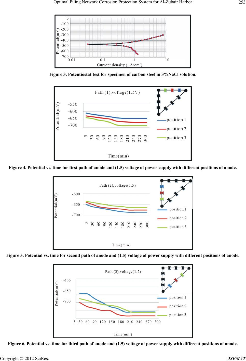
Figures 4-6 is more than –800 mV at different paths and
positions of anode with 1.5 voltage of power supply;
therefore, the selected voltage of power supply does not
protect the steel piles because their potential is more than
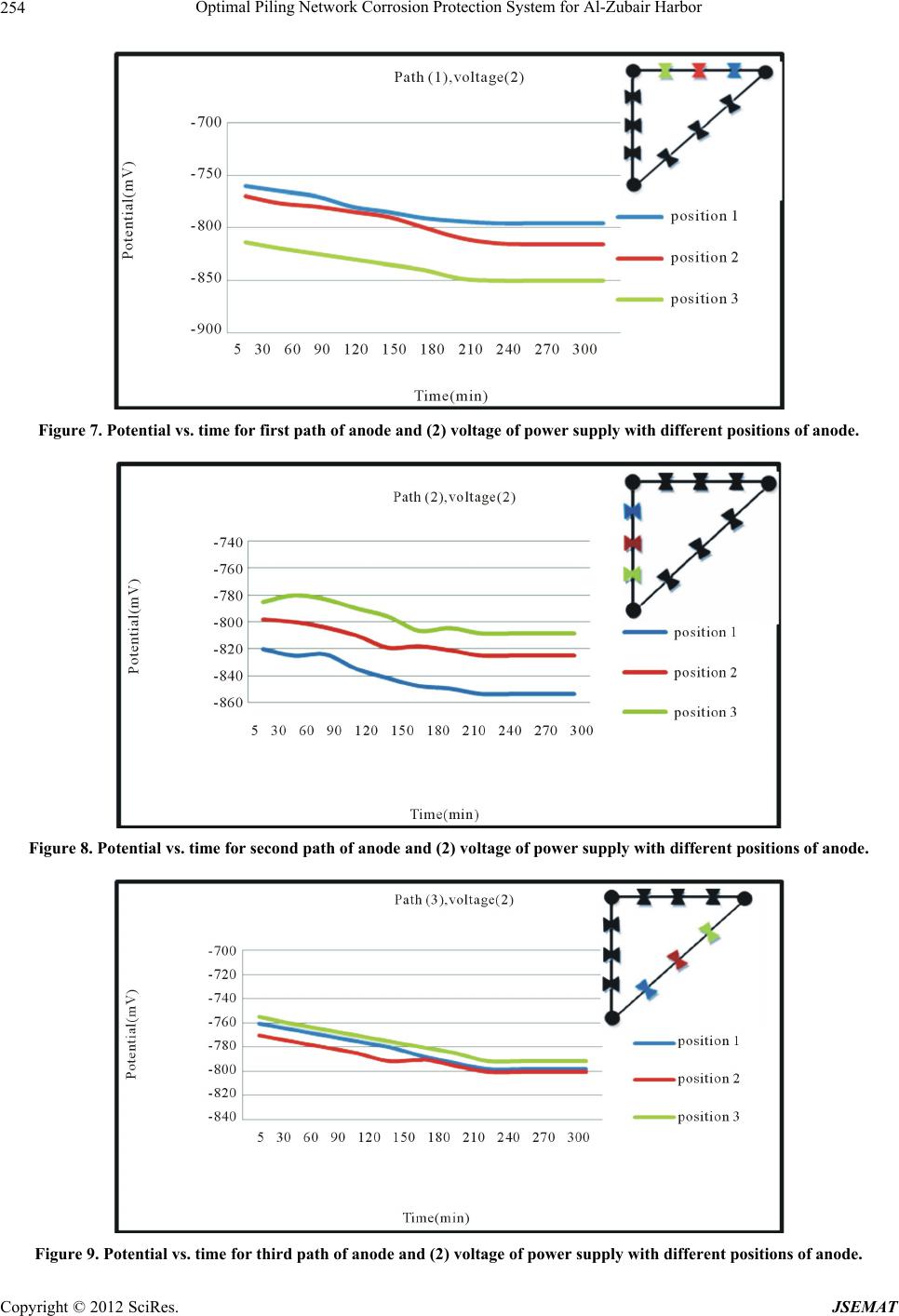
the desired value. In Figure 7, the voltage of power sup-
ply is 2V and the anode is set on the first path, when the
anode place is in the first position, the distance between
the anode and the piles equals to 17 cm and the value of
protection potential is –796 mV. In position (2) the dis-
tance between the anode and the piles is equal to 16 cm
and the protection potential is –816 mV. At position (3)
the distance between the anode and the piles equals 15
cm and protection potential is –850 mV. There is an in-
verse relationship between protection potential and the
distance between the anode and cathodes, this relation-
ship is given by the following Equation [10]:
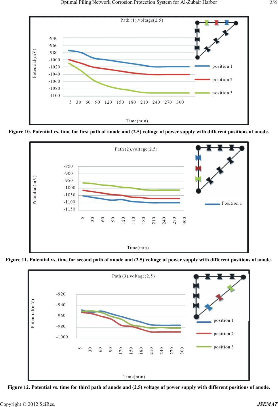
the protection potential is less than –800 mV. In Figure
10, voltage of power supply is 2.5 V and the anode is set
on the first path. When the anode is in the first position,
the distance between the anode and the piles is equal to
17cm and protection potential is –1019 mV, in the sec-
ond position the distance between the anode and the piles
is 16 cm and protection potential is –1041 mV, at posi-
tion (3) the distance between the anode and the piles is
15 cm and protection potential is –1091 mV. It can be
observed that protection potential is increased in negative
direction when the distance between the anode and cath-
odes is decreased. In Figure 11, voltage of power supply
is 2.5 V and the anode is set at the second path, the dis-
tance among the anode and the piles in position (1) is 15
cm and protection potential is –1096 mV, the distance
among the anode and the piles in position (2) is 16 cm
and protection potential is –1050 mV, in position (3) the
distance among the anode and the piles is equal to 17 cm
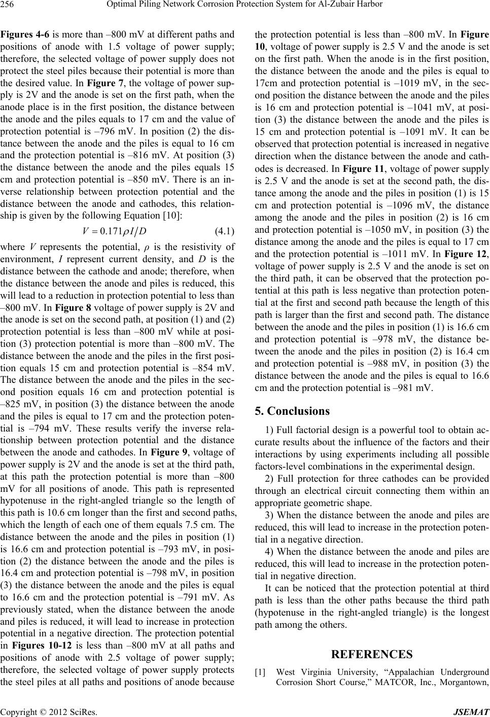
and the protection potential is –1011 mV. In Figure 12,
voltage of power supply is 2.5 V and the anode is set on
the third path, it can be observed that the protection po-
tential at this path is less negative than protection poten-
tial at the first and second path because the length of this
path is larger than the first and second path. The distance
between the anode and the piles in position (1) is 16.6 cm
and protection potential is –978 mV, the distance be-
tween the anode and the piles in position (2) is 16.4 cm
and protection potential is –988 mV, in position (3) the
distance between the anode and the piles is equal to 16.6
cm and the protection potential is –981 mV.
0.171VID
(4.1)
where V represents the potential, ρ is the resistivity of
environment, I represent current density, and D is the
distance between the cathode and anode; therefore, when
the distance between the anode and piles is reduced, this
will lead to a reduction in protection potential to less than
–800 mV. In Figure 8 voltage of power supply is 2V and
the anode is set on the second path, at position (1) and (2)
protection potential is less than –800 mV while at posi-
tion (3) protection potential is more than –800 mV. The
distance between the anode and the piles in the first posi-
tion equals 15 cm and protection potential is –854 mV.
The distance between the anode and the piles in the sec-
ond position equals 16 cm and protection potential is
–825 mV, in position (3) the distance between the anode
and the piles is equal to 17 cm and the protection poten-
tial is –794 mV. These results verify the inverse rela-
tionship between protection potential and the distance
between the anode and cathodes. In Figure 9, voltage of
power supply is 2V and the anode is set at the third path,
at this path the protection potential is more than –800
mV for all positions of anode. This path is represented
hypotenuse in the right-angled triangle so the length of
this path is 10.6 cm longer than the first and second paths,
which the length of each one of them equals 7.5 cm. The
distance between the anode and the piles in position (1)
is 16.6 cm and protection potential is –793 mV, in posi-
tion (2) the distance between the anode and the piles is
16.4 cm and protection potential is –798 mV, in position
(3) the distance between the anode and the piles is equal
to 16.6 cm and the protection potential is –791 mV. As
previously stated, when the distance between the anode
and piles is reduced, it will lead to increase in protection
potential in a negative direction. The protection potential
in Figures 10-12 is less than –800 mV at all paths and
positions of anode with 2.5 voltage of power supply;
therefore, the selected voltage of power supply protects
the steel piles at all paths and positions of anode because
5. Conclusions
1) Full factorial design is a powerful tool to obtain ac-
curate results about the influence of the factors and their
interactions by using experiments including all possible
factors-level combinations in the experimental design.
2) Full protection for three cathodes can be provided
through an electrical circuit connecting them within an
appropriate geometric shape.
3) When the distance between the anode and piles are
reduced, this will lead to increase in the protection poten-
tial in a negative direction.
4) When the distance between the anode and piles are
reduced, this will lead to increase in the protection poten-
tial in negative direction.
It can be noticed that the protection potential at third
path is less than the other paths because the third path
(hypotenuse in the right-angled triangle) is the longest
path among the others.
REFERENCES
[1] West Virginia University, “Appalachian Underground
Corrosion Short Course,” MATCOR, Inc., Morgantown,
Optimal Piling Network Corrosion Protection System for Al-Zubair Harbor 257
2009.
[2] R. W. Revie and H. H. Uhlig, “Corrosion and Corrosion
Control: An Introduction to Corrosion Science and Engi-
neering,” 4th Edition, John Wiley & Sons, Hoboken,
2008. doi:10.1002/9780470277270
[3] M. Al-Otaibi, “The Application of Beasy Software to
Simulate Cathodic Protection of Pipelines and Storage
Tanks,” M.Sc. Thesis, The University of British Colum-
bia, Vancouver, 2010.
[4] Y. M. Abdu Al-Sahib, “The Use of Al-Zn Alloys as Sac-
rificial Anodes to Protect Buried Steel Pipes,” M.Sc.
Thesis, University of Technology, Baghdad, 2010.
[5] G. A. Ali, “Identification of Polarization Parameters for
Cathodic Protection By Using Neural Network,” M.Sc.
Thesis, University of Technology, Baghdad, 2007.
[6] R. L. Mason, R. F. Gunst and J. L. Hess, “Statistical De-
sign and Analysis of Experiments,” 2nd Edition, John
Wiley & Sons, Hoboken, 2003. doi:10.1002/0471458503
[7] R. A. Salman, “Optimal Piling Network Corrosion Protec-
tion System for AL-Zubair Harbor,” M.Sc. Thesis, Univer-
sity of Technology, Baghdad, 2012.
[8] International SEMATECH and International SEMATECH
Member Companies, “NIST/SEMATECH e-Handbook of
Statistical Methods,” 2010.
http://www.itl.nist.gov/div898/handbook/
[9] R. L. Mason, R. F. Gunst and J. L. Hess, “Statistical De-
sign and Analysis of Experiments,” 2nd Edition, John
Wiley & Sons, Hoboken, 2003. doi:10.1002/0471458503
[10] M. H. Hafiz, “Modeling of Pipeline Corrosion Control by
Cathodic Protection,” Ph.D. Thesis, University of Tech-
nology, Baghdad, 2006.
Copyright © 2012 SciRes. JSEMAT