 Open Journal of Applied Sciences, 2012, 2, 198-208 doi:10.4236/ojapps.2012.23030 Published Online September 2012 (http :/ /www.SciRP.org/journal/ojapps) Kansei Engineering Applied to the Form Design of Injection Molding Machines Ming-Shyan Huang*, Hung-Cheng Tsai, Wei-Wen Lai Department of Mechanical and Automation Engineering and Graduate Institute of Industrial Design, National Kaohsiung First University of Science and Technology, Kaohsiung, Taiwan (China) Email: *mshuang@nkfust.edu.tw Received June 19, 2012; revised July 20, 2012; accepted July 30, 2012 ABSTRACT This study investigated the relationship between a subject’s evaluation of injection molding machines (IMMs) and for- mal design features using Kansei engineering. This investigation used 12 word pairs to evaluate the IMM configurations and employed the semantic differential method to explore the perception of 60 interviewees of 12 examples. The re- lationship between product featu re design and corresponding wo rds was derived by multiple regression an alysis. Factor analysis reveals that the 12 examples can be categorized as two styles—advanced style and succinct style. For the ad- vanced style, an IMM should use a rectangular form for the clamping-unit cover and a full-cover for the injection-unit. For the succinct style, the IMM configuration should use a beveled form for the safety cover and a vertical rectangular form for the clamping-unit cover. Quantitative data and suggested guidelines for the relationship between design fea- tures and interviewee evaluations are useful to product designers when formulating design strategies. Keywords: Category Classification; Kansei Engineering; Injection Molding Machines; Product Feature Design; Semantic Differential Method 1. Introduction The product development trend is changing to a user- oriented development, i.e., user feelings are recognized as invaluable during product development. Thus, designers must consider user preferences and needs to increase product success. Product configuration is linked with user perceptions of products, and the resulting product is a reflection of customer philosophy and preferences. How to investigate the feelings and preferences of cus- tomers about a product and then utilizing these feelings and preferences as a reference when designing products has become an important issue. Product design is a process during which designers de- liver a product design to customers via a product that satisfies user feelings and preferences. However, opin- ions of designers and users typically differ. Mental con- cepts of users are often difficult to identify and, cones- quently, a satisfactory product is difficult to design. In particular, designing injection molding machines (IMMs) often lacks user feedback and relies heavily on technical specifications and imaginary targets of manufact urers. Kansei engineering, founded by Nagamachi in 1970, is a methodology for systematically exploring user percep- tions about a product and translating these perceptions into design parameters [1]. If consumer feelings can be implemented in new product designs, consumers would be satisfied with such products. The most important task in Kansei engineering is to survey customers to identify their preferences, or kansei, at the start of the product development process. The scale of kansei words, con- sisting of the semantic differential proper adjectives, is needed for psychological measurements of customers. If customer kansei is determined accurately, product de- velopment will be extremely successful. Kansei engineering has been applied when designing automobiles, construction machinery, electrical home appliances, office machines, and cosmetics [2-7]. Roy et al. [8] utilized web-based cell phone images and ques- tionnaires to gather data associated with emotional re- sponses to existing products that can then be used when designing new cell phones and pursuing added value in the consumer marketplace. They developed a method that can be used to reduce arbitrary decision making, which is often applied during the product design process. Chang and Wu [9] explored the mechanisms that domi- nate user mental models for product form classification. After analyzing real mobile phones, they concluded that local features were the dominant mechanisms for classi- fying a large number of similar products. Classification based on real product samples can help when exploring *Corresponding a uthor. Copyright © 2012 SciRes. OJAppS 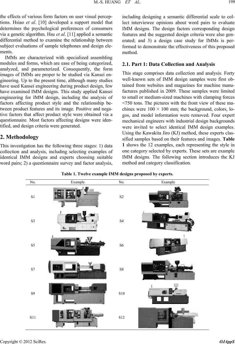 M.-S. HUANG ET AL. 199 the effects of various form factors on user visual percep- tions. Hsiao et al. [10] developed a support model that determines the psychological preferences of consumers via a genetic algorithm. Hsu et al. [11] applied a semantic differential method to examine the relationship between subject evaluations of sample telephones and design ele- ments. IMMs are characterized with specialized assembling modules and forms, which are ease of being categorized, analyzed, and parameterized. Consequently, the form images of IMMs are proper to be studied via Kansei en- gineering. Up to the present time, although many studies have used Kansei engineering during product design, few have examined IMM designs. This study applied Kansei engineering for IMM design, including the analysis of factors affecting product style and the relationship be- tween product features and its image. Positive and nega- tive factors that affect product style were obtained via a questionnaire. Most factors affecting designs were iden- tified, and design criteria were generated. 2. Methodology This investigation has the following three stages: 1) data collection and analysis, including selecting examples of identical IMM designs and experts choosing suitable word pairs; 2) a qu estionnaire survey and factor analysis, including designing a semantic differential scale to col- lect interviewee opinions about word pairs to evaluate IMM designs. The design factors corresponding design features and the suggested design criteria were also gen- erated; and 3) a design case study for IMMs is per- formed to demonstrate the effectiveness of this proposed method. 2.1. Part 1: Data Collection and Analysis This stage comprises data collection and analysis. Forty well-known sets of IMM design samples were first ob- tained from websites and magazines for machine manu- factures published in 2009. These samples were limited to small or medium-sized machines with clamping forces <750 tons. The pictures with the front view of these ma- chines were 100 × 100 mm; the background, colors, lo- gos, and model information were removed. Four expert mechanical engineers with industrial design backgrounds were invited to select identical IMM design examples. Using the Kawakita Jiro (KJ) method, these experts clas- sified samples based on their features and images. Table 1 shows the 12 examples, each representing the style in one category selected by experts. These sets are example IMM designs. The following section introduces the KJ method and category classification. Table 1. Twelve example IMM designs proposed by experts. No. Example No.Example S1 S2 S3 S4 S5 S6 S7 S8 S9 S10 S11 S12 Copyright © 2012 SciRes. OJAppS  M.-S. HUANG ET AL. 200 2.1.1. KJ Me thod The KJ method, developed in 1965, achieves efficient group communication and has become a very popular decision-making method for expert groups. The KJ method uses one card that states a single concept and then categorizes cards into several groups. Experts are then required to select one representative card from each group [12]. 2.1.2. Category Classification and Word Pai r Selection Category classification is utilized to convert a verbal product description into a detailed design. A literature survey identified 342 word pairs used in design descrip- tions [13-15]. Based on these word data, experts choose appropriate adjectives to describe IMM designs. Adjec- tives for describing IMM designs are used only when more than 50% the experts agree. The selected best 12 word pairs were as follows: traditional-modern, complex- simple, massive-compact, tacky-sleek, inferior-superior, ubi- quitous-unique, imitative-innovative, rough-delicate, curvilin- ear-foursquare, cheap-expensive, dirty-clean, and disagree- able-agreeable (Table 2). 2.2. Part 2: Questionnaire Survey and Factor Analysis This section verifies the 12 word pairs for IMM designs. The verification process involves conducting a question- naire survey administered to experts to select appropriate design attributes, and analyzing samples using word pair data to generate suitable adjectives for describing IMM configurations. In designing the questionnaire, this study utilized a seven-level semantic differential (SD) scale (Table 3) to identify the degree to which a word pair describes an Table 2. Word pairs describing the IMM configur ation. Word pairs Traditional-Modern Complex-Simple Massive-Compact Tacky-Sleek Inferior-Superior Ubiquitous-Unique Imitative-Innovative Rough-Delicate Curvilinear-Foursquare Cheap-Expensive Dirty-Clean Disagreeable-Agreeable Table 3. The IMM semantic differential table. 1234 5 6 7 Traditional □ □ □ □ □ □ □ Modern Complex □ □ □ □ □ □ □ Simple Massive □ □ □ □ □ □ □ Compact Tacky □ □ □ □ □ □ □ Sleek Inferior □ □ □ □ □ □ □ Superior Ubiquitous □□ □ □ □ □ □ Unique Imitative □ □ □ □ □ □ □ Innovative Rough □ □ □ □ □ □ □ Delicate Curvilinear □ □ □ □ □ □ □ Foursquare Cheap □ □ □ □ □ □ □ Expensive Dirty □ □ □ □ □ □ □ Clean Disagreeable □ □ □ □ □ □ □ Agreeable IMM design. To simply the style design problem, the color factor is excluded in this study. Thus, 12 IMM examples with different forms were all in gray and with- out any logos. Interviewees evaluated each set of IMM examples using the 12 word pairs. For instance, Nos. 1, 4, and 7 represent full agreement to the left adjective, neu- tral opinion, and full agreement to the right adjective, respectively (Table 3). To assess the 12 example IMM designs, this study in- terviewed 60 experts of 38 males and 22 females from two different groups—40 experts with work experience in mechanical engineering, and 20 experts with work experience in product design. The questionnaires for the 12 samples were given to these experts to establish the relationship between form features and image percep- tions of IMM designs. Experts were asked to express their judgments by setting the levels on SD scales for all word pairs in the questionnaires. From the average judgment values of these experts, the significance calcu- lated value exceeded 0.05 and it represents the opinions from the two groups are identical and thus should be combined in subsequent analyses. To reveal the reliability and effectiveness of question- naire survey, reliability analysis is conducted in this study. In the reliability test, Cronbach and Split-half coefficients are calculated. A high value of reliability coefficient means the questionnaire survey is stable, namely, the consistency of survey results conducted in different durations. For evaluating potential variables, Copyright © 2012 SciRes. OJAppS 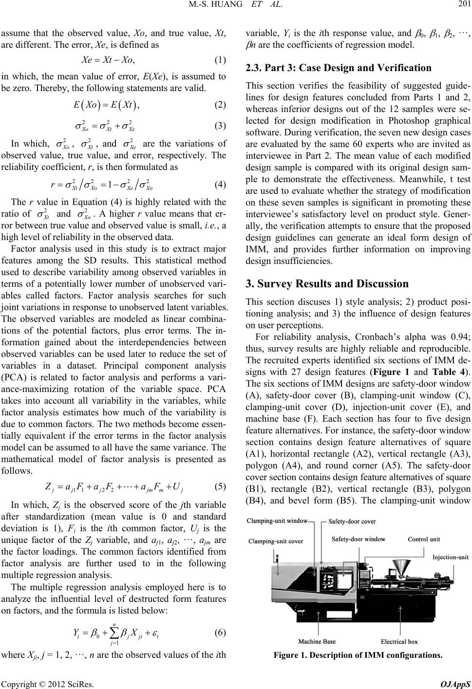 M.-S. HUANG ET AL. 201 assume that the observed value, Xo, and true value, Xt, are different. The error, Xe, is defined as , eXtXo (1) in which, the mean value of error, E(Xe), is assumed to be zero. Thereby, the following statements are valid. ,EXo EXt (2) 22 XoXt Xe 2 (3) In which, 2 Xo , Xt 2 , and Xe 2 are the variations of observed value, true value, and error, respectively. The reliability coefficient, r, is then formulated as 22 22 1 Xt XoXe Xo r (4) The r value in Equation (4) is highly related with the ratio of 2 Xt and 2 Xo . A higher r value means that er- ror between true value and observed value is small, i.e., a high level of reliability in the observed data. Factor analysis used in this study is to extract major features among the SD results. This statistical method used to describe variability among observed variables in terms of a potentially lower number of unobserved vari- ables called factors. Factor analysis searches for such joint variations in respons e to unobserved latent variables. The observed variables are modeled as linear combina- tions of the potential factors, plus error terms. The in- formation gained about the interdependencies between observed variables can be used later to reduce the set of variables in a dataset. Principal component analysis (PCA) is related to factor analysis and performs a vari- ance-maximizing rotation of the variable space. PCA takes into account all variability in the variables, while factor analysis estimates how much of the variability is due to common factors. The two methods become essen- tially equivalent if the error terms in the factor analysis model can be assumed to all have the same variance. The mathematical model of factor analysis is presented as follows. 112 2 jj jmmj aFaFa FU (5) In which, Zj is the observed score of the jth variable after standardization (mean value is 0 and standard deviation is 1), Fi is the ith common factor, Uj is the unique factor of the Zj variable, and aj1, aj2, ···, ajm are the factor loadings. The common factors identified from factor analysis are further used to in the following multiple regression analysis. The multiple regression analysis employed here is to analyze the influential level of destructed form features on factors, and the formula is listed below: 01 n ijj j YX it (6) where Xji, j = 1, 2, ···, n are the observed values of the ith variable, Yi is the ith response value, and 0, 1, 2, ···, n are the coefficients of regression model. 2.3. Part 3: Case Design and Verification This section verifies the feasibility of suggested guide- lines for design features concluded from Parts 1 and 2, whereas inferior designs out of the 12 samples were se- lected for design modification in Photoshop graphical software. During verification, the seven new design cases are evaluated by the same 60 experts who are invited as interviewee in Part 2. The mean value of each modified design sample is compared with its original design sam- ple to demonstrate the effectiveness. Meanwhile, t test are used to evaluate whether the strategy of modification on these seven samples is significant in promoting these interviewee’s satisfactory level on product style. Gener- ally, the verification attempts to ensure that the proposed design guidelines can generate an ideal form design of IMM, and provides further information on improving design insufficiencies. 3. Survey Results and Discussion This section discuses 1) style analysis; 2) product posi- tioning analysis; and 3) the influence of design features on user perceptions. For reliability analysis, Cronbach’s alpha was 0.94; thus, survey results are highly reliable and reproducible. The recruited experts identified six sections of IMM de- signs with 27 design features (Figure 1 and Table 4). The six sections of IMM designs are safety-door window (A), safety-door cover (B), clamping-unit window (C), clamping-unit cover (D), injection-unit cover (E), and machine base (F). Each section has four to five design feature alternatives. For instance, the safety-door window section contains design feature alternatives of square (A1), horizontal rectangle (A2), vertical rectangle (A3), polygon (A4), and round corner (A5). The safety-door cover section contains design feature alternatives of square (B1), rectangle (B2), vertical rectangle (B3), polygon (B4), and bevel form (B5). The clamping-unit window Figure 1. Description of IMM configurations. Copyright © 2012 SciRes. OJAppS 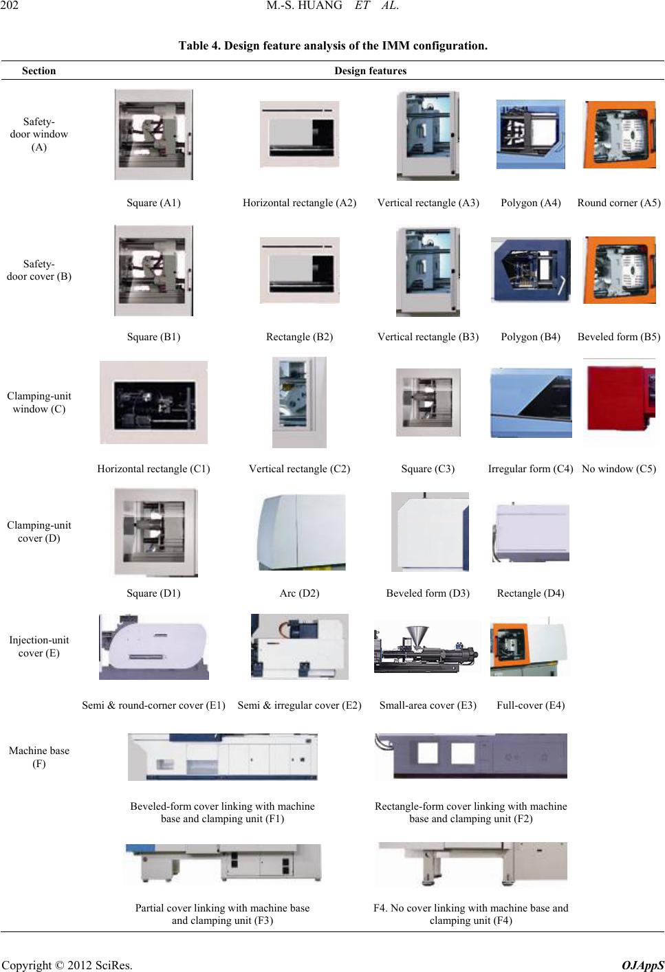 M.-S. HUANG ET AL. Copyright © 2012 SciRes. OJAppS 202 Table 4. Design feature analysis of the IMM configuration. Section Design features Safety- door window (A) Square (A1) Horizontal rectangle (A2) Vertical rectangl e (A3)Polygon (A4 ) Round corner (A5) Safety- door cover (B) Square (B1) Rectangle (B2) Vertical rectangle (B3)Polygon (B4) Beveled form (B5) Clamping-unit window (C) Horizontal rectangle (C1) Vertical rectangle (C2) Square (C3) Irregular form (C4) No window (C5) Clamping-unit cover (D) Square (D1) Arc (D2) Beveled form (D3) Rectangle (D4) Injection-unit cover (E) Semi & round-corner cover (E1) Semi & irregular cover (E2)Small-area cover (E3) Full-cover (E4) Machine base (F) Beveled-form cover linking wit h machine base and clampi n g unit (F1) Rectangle-form cover linking with machine base and clampi n g unit (F2) Partial cover linking with machine base and clamping unit (F3) F4. No cover linking with machine base and clamping unit (F4) 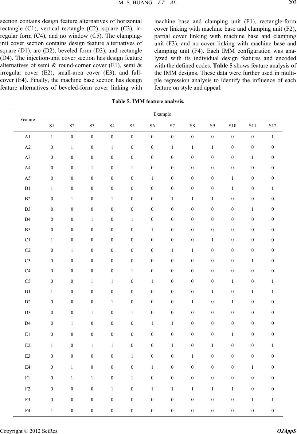 M.-S. HUANG ET AL. 203 section contains design feature alternatives of horizontal rectangle (C1), vertical rectangle (C2), square (C3), ir- regular form (C4), and no window (C5). The clamping- init cover section contains design feature alternatives of square (D1), arc (D2), beveled form (D3), and rectangle (D4). The injection-unit cover section has design feature alternatives of semi & round-corner cover (E1), semi & irregular cover (E2), small-area cover (E3), and full- cover (E4). Finally, the machine base section has design feature alternatives of beveled-form cover linking with machine base and clamping unit (F1), rectangle-form cover linking with machine base and clamping unit (F2), partial cover linking with machine base and clamping unit (F3), and no cover linking with machine base and clamping unit (F4). Each IMM configuration was ana- lyzed with its individual design features and encoded with the defined codes. Table 5 shows feature analysis of the IMM designs. These data were further used in multi- ple regression analysis to identify the influence of each feature on style and appeal. Table 5. IMM feature analysis. Example Feature S1 S2 S3 S4 S5 S6 S7 S8 S9 S10 S11 S12 A1 1 0 0 0 0 0 0 0 0 0 0 1 A2 0 1 0 1 0 0 1 1 1 0 0 0 A3 0 0 0 0 0 0 0 0 0 0 1 0 A4 0 0 1 0 1 0 0 0 0 0 0 0 A5 0 0 0 0 0 1 0 0 0 1 0 0 B1 1 0 0 0 0 0 0 0 0 1 0 1 B2 0 1 0 1 0 0 1 1 1 0 0 0 B3 0 0 0 0 0 0 0 0 0 0 1 0 B4 0 0 1 0 1 0 0 0 0 0 0 0 B5 0 0 0 0 0 1 0 0 0 0 0 0 C1 1 0 0 0 0 0 0 0 1 0 0 0 C2 0 1 0 0 0 0 1 1 0 0 0 0 C3 0 0 0 0 0 0 0 0 0 0 1 0 C4 0 0 0 0 1 0 0 0 0 0 0 0 C5 0 0 1 1 0 1 0 0 0 1 0 1 D1 1 0 0 0 0 0 0 0 1 0 1 1 D2 0 0 0 1 0 0 0 1 0 1 0 0 D3 0 0 1 0 1 0 0 0 0 0 0 0 D4 0 1 0 0 0 1 1 0 0 0 0 0 E1 0 0 0 0 0 0 0 0 0 1 0 0 E2 1 0 1 1 0 0 1 0 1 0 0 1 E3 0 0 0 0 1 0 0 1 0 0 0 0 E4 0 1 0 0 0 1 0 0 0 0 1 0 F1 0 1 1 0 1 0 0 0 0 0 0 0 F2 0 0 0 1 0 1 1 1 1 1 0 0 F3 0 0 0 0 0 0 0 0 0 0 1 1 F4 1 0 0 0 0 0 0 0 0 0 0 0 Copyright © 2012 SciRes. OJAppS  M.-S. HUANG ET AL. 204 3.1. Style Analysis Table 6 lists semantic differential valu es of the word pair evaluations of the 12 examples (S1-S12); an average >5.0 indicates a high degree of agreement to the right adjective, that of 3.0 - 5.0 is neutral agreement between the word pair, and that <3.0 indicates a high degree of agreement to the left adjective. Analytical results are as follows. 1) Examples with a high degree of agreement were S1 for “foursquare” and “clean,” S2 for “modern” and “su- perior,” S6 for “clean,” S9 for “foursquare,” S10 for “simple” and “clean,” S11 for “modern” and “four- square,” and S12 for “foursquare”. 2) The only example with a disagreement was S12 for “compact” only. 3) Images of “foursquare” and “clean” had the highest average scores, indicating that most examples have these styles. Table 7 also lists factor analysis results for these 12 examples; the three highest scores are marked with solid circles and the three lowest scores are marked empty circles. Thus, S2, S6, S10, and S11 are most agreeable described by various word pairs. Additionally, S8, S9, and S12 have the lowest agree ment for word pairs. Nota- bly, S1, S11, and S12 are examples of “foursquare and S2, S3, and S10 are those of “curvilinear”. Since the word “foursquare” describes product appearance and without assessment, it is analyzed individually. Table 6. Semantic differential values. Styling High degree (>5.0) Neutral degree (3.0 - 5.0) Reverse degree (<3.0) Average Modern S2, S11 (16.7%) S1, S3, S4, S5, S6, S7, S8, S9, S10, S12 (83. 3% ) 4.33 Simple S10 (8.3%) S1, S2, S3, S4, S5, S6, S7, S8, S9, S11, S12 (91.7%) 4.27 Compact S1, S2, S3, S4, S5, S6, S7, S8, S9, S10, S11 (91.7%) S12 (8.3%) 3.70 Sleek S2 (8.3%) S1, S3, S4, S5, S6, S7, S8 , S9, S10, S11, S12 (91. 7 %) 4.17 Superior S2 (8.3%) S1, S3, S4, S5, S6, S7, S8, S9, S10, S11, S12 (91.7%) 4.00 Unique S1, S2, S3, S4, S5, S6, S7, S8, S9, S10, S11, S12 (100%) 4.01 Innovative S11 (8.3%) S1, S2, S3, S4, S5, S6, S7, S8, S9, S10, S12 (91.7%) 4.13 Delicate S1, S2, S3, S4, S5, S6, S7, S8, S9, S10, S11, S12 (100%) 4.12 Foursquare S1, S9, S11, S12 (3 3% ) S2, S3, S4, S5, S6, S7 , S8, S10 (67%) 4.77 Expensive S2 (8.3%) S1, S3, S4, S5, S6 , S 7 , S8, S9, S10, S11, S12 (91.7%) 4.09 Clean S1, S6, S10 (25%) S2, S3, S4, S5, S7, S8, S9, S11, S12 (75%) 4.62 Agreeable S1, S2, S3, S4, S5, S6, S7, S8, S9, S10, S11, S12 (100%) 4.34 Table 7. Factor analysis of 12 IMM designs. Example Styling S1 S2 S3 S4 S5 S6 S7 S8 S9 S10 S11 S12 Modern ● ○ ○ ● ● ○ Simple ● ○ ● ○ ● ○ Compact ○ ● ○ ● ● ○ Sleek ○ ● ● ○ ● ○ Superior ○ ● ● ○ ● ○ Unique ○ ● ○ ● ● ○ Innovative ● ○ ○ ● ● ○ Delicate ● ○ ○ ● ● ○ Foursquare ● ○ ○ ○ ● ● Expensive ○ ● ● ○ ● ○ Clean ● ○ ● ○ ● ○ Agreeable ● ● ○ ● ○ ○ ●: Highly relative; ○: Lowly relative. Copyright © 2012 SciRes. OJAppS 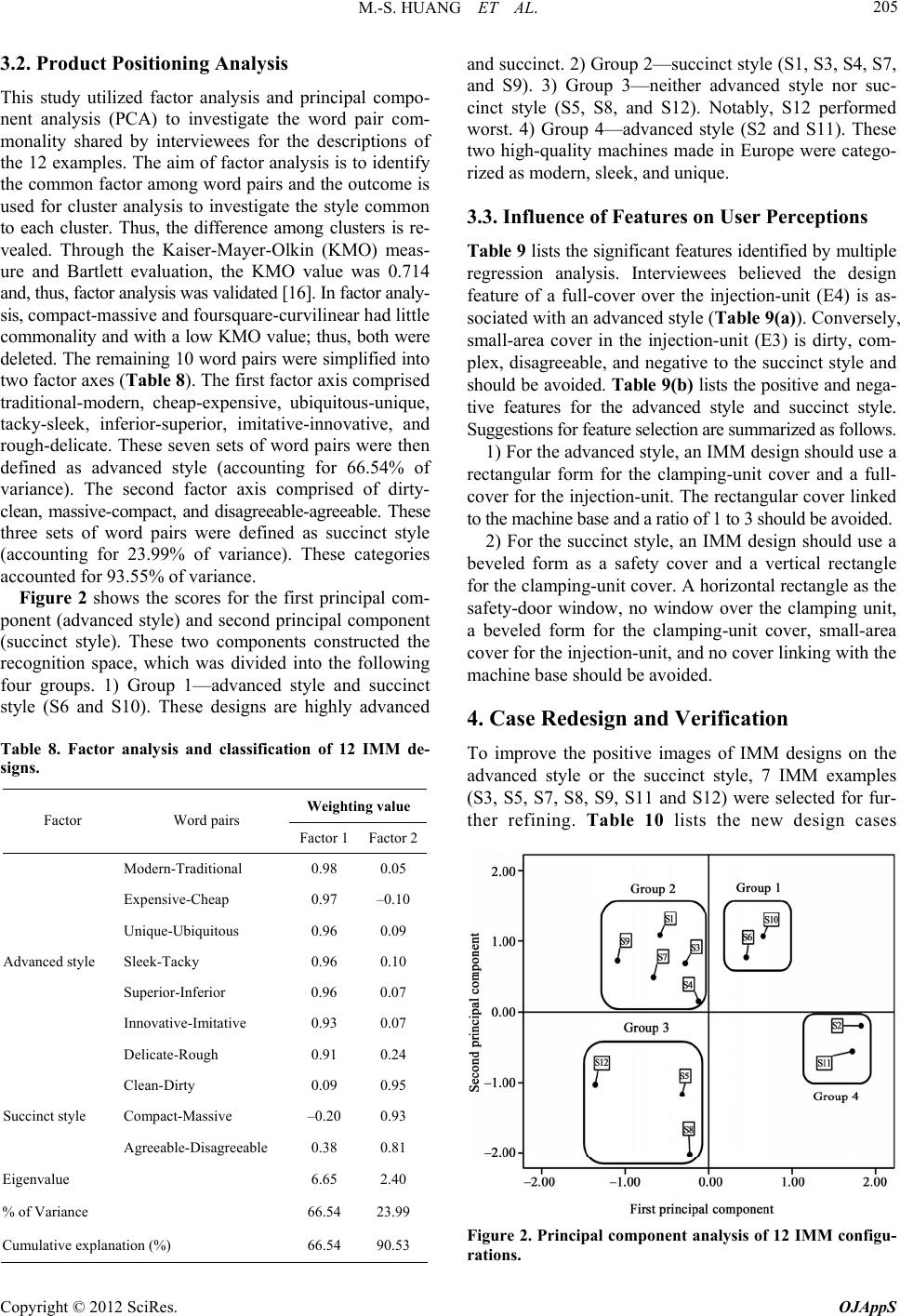 M.-S. HUANG ET AL. 205 3.2. Product Positioning Analysis This study utilized factor analysis and principal compo- nent analysis (PCA) to investigate the word pair com- monality shared by interviewees for the descriptions of the 12 examples. The aim of factor analysis is to identify the common factor among word pairs and the outcome is used for cluster analysis to investigate the style common to each cluster. Thus, the difference among clusters is re- vealed. Through the Kaiser-Mayer-Olkin (KMO) meas- ure and Bartlett evaluation, the KMO value was 0.714 and, thus, factor analysis was validated [16]. In factor analy- sis, compact-massive and foursquare-curvilinear had little commonality and with a low KMO value; thus, both were deleted. The rema ining 10 word pairs were simpl ified into two factor axes (Table 8). The first factor axis comprised traditional-modern, cheap-expensive, ubiquitous-unique, tacky-sleek, inferior-superior, imitative-innovative, and rough-delicate. These seven sets of word pairs were then defined as advanced style (accounting for 66.54% of variance). The second factor axis comprised of dirty- clean, massive-compact, and disagreeable-agreeable. These three sets of word pairs were defined as succinct style (accounting for 23.99% of variance). These categories accounted for 93.55% of variance. Figure 2 shows the scores for the first principal com- ponent (advanced style) and second principal component (succinct style). These two components constructed the recognition space, which was divided into the following four groups. 1) Group 1—advanced style and succinct style (S6 and S10). These designs are highly advanced Table 8. Factor analysis and classification of 12 IMM de- signs. Weighting value Factor Word pairs Factor 1 Factor 2 Modern-Traditional 0.98 0.05 Expensive-Cheap 0.97 –0.10 Unique-Ubiquitous 0.96 0.09 Sleek-Tacky 0.96 0.10 Superior-Inferior 0.96 0.07 Innovative-Imitative 0.93 0.07 Advanced style Delicate-Rough 0.91 0.24 Clean-Dirty 0.09 0.95 Compact-Massive –0.20 0.93 Succinct style Agreeable-Disagreeable 0.38 0.81 Eigenvalue 6.65 2.40 % of Variance 66.54 23.99 Cumulative explanation (%) 66.54 90.53 and succinct. 2) Group 2—succin ct style (S1, S3, S4, S7, and S9). 3) Group 3—neither advanced style nor suc- cinct style (S5, S8, and S12). Notably, S12 performed worst. 4) Group 4—advanced style (S2 and S11). These two high-quality machines made in Europe were catego- rized as modern, sleek, and unique. 3.3. Influence of Features on User Perceptions Table 9 lists th e significant features id entified by multip le regression analysis. Interviewees believed the design feature of a full-cover over the injection-unit (E4) is as- sociated with an advanced style (Table 9(a)). Conversely, small-area cover in the injection-unit (E3) is dirty, com- plex, disagreeable, and negative to the succinct style and should be avoided. Table 9(b) lists the positive and nega- tive features for the advanced style and succinct style. Suggestions for feature selection are summarized as follows. 1) For the advanced style, an IMM design should use a rectangular form for the clamping-unit cover and a full- cover for the injection-unit. The rectangular co ver linked to the machine base and a ratio of 1 to 3 should be avoided. 2) For the succinct style, an IMM design should use a beveled form as a safety cover and a vertical rectangle for the clamping-unit cover. A horizontal rectangle as the safety-door window, no window over the clamping unit, a beveled form for the clamping-unit cover, small-area cover for the injection- unit, an d no cover link ing with the machine base should be avoided. 4. Case Redesign and Verification To improve the positive images of IMM designs on the advanced style or the succinct style, 7 IMM examples (S3, S5, S7, S8, S9, S11 and S12) were selected for fur- ther refining. Table 10 lists the new design cases Figure 2. Principal component analysis of 12 IMM configu- rations. Copyright © 2012 SciRes. OJAppS 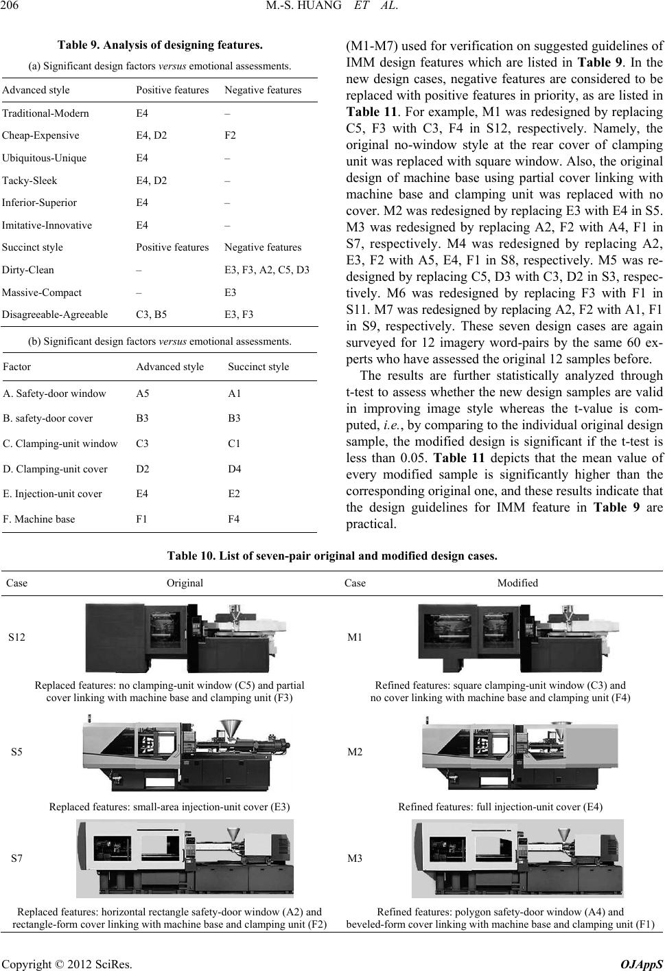 M.-S. HUANG ET AL. 206 Table 9. Analysis of designing features. (a) Significant design factors versus emotional assessments. Advanced style Positive features Negative features Traditional-Modern E4 – Cheap-Expensive E4, D2 F2 Ubiquitous-Unique E4 – Tacky-Sleek E4, D2 – Inferior-Superior E4 – Imitative-Innovative E4 – Succinct style Positive features Negative features Dirty-Clean – E3, F3, A2, C5, D3 Massive-Compact – E3 Disagreeable-Agreeable C3, B5 E3, F3 (b) Significant design factors versus emotional assessments. Factor Advanced style Succinct styl e A. Safety-door window A5 A1 B. safety-door cover B3 B3 C. Clamping-unit window C3 C1 D. Clamping-unit cover D2 D4 E. Injection-unit cover E4 E2 F. Machine base F1 F4 (M1-M7) us ed f or ve rificatio n on suggested g u idelin es of IMM design features which are listed in Table 9. In the new design cases, negative features are considered to be replaced with pos itive features in priority, as are listed in Table 11. For example, M1 was redesigned by replacing C5, F3 with C3, F4 in S12, respectively. Namely, the original no-window style at the rear cover of clamping unit was replaced with square window. Also, the original design of machine base using partial cover linking with machine base and clamping unit was replaced with no cover. M2 was redesigned by replacing E3 with E4 in S5. M3 was redesigned by replacing A2, F2 with A4, F1 in S7, respectively. M4 was redesigned by replacing A2, E3, F2 with A5, E4, F1 in S8, respectively. M5 was re- designed by replacing C5, D3 with C3, D2 in S3, respec- tively. M6 was redesigned by replacing F3 with F1 in S11. M7 was redesigned by replacing A2, F2 with A1, F1 in S9, respectively. These seven design cases are again surveyed for 12 imagery word-pairs by the same 60 ex- perts who have assessed the original 12 samples before. The results are further statistically analyzed through t-test to assess whether the new design samples are valid in improving image style whereas the t-value is com- puted, i.e., by comparing to the ind ividu al origin al d esign sample, the modified design is significant if the t-test is less than 0.05. Table 11 depicts that the mean value of every modified sample is significantly higher than the corresponding original one, and these results indicate that the design guidelines for IMM feature in Table 9 are practical. Table 10. List of seven-pair original and modified design cases. Case Original CaseModified S12 M1 Replaced features: no clamping-unit window (C5) and partial cover linking with machine base and clamping unit (F3) Refined features: square clamping-unit window (C3) and no cover linking with machine base and clamping unit (F4) S5 M2 Replaced features: small-area injection-unit cover (E3) Refined features: full injection-unit cover (E4) S7 M3 Replaced features: horizontal rectangle safety-door window (A2) and rectangle-form cover linking wit h machine base and clamping unit (F2) Refined features: polygon safety-do o r window (A4) and beveled-form cover linking with machine b ase and clamping unit (F1) Copyright © 2012 SciRes. OJAppS 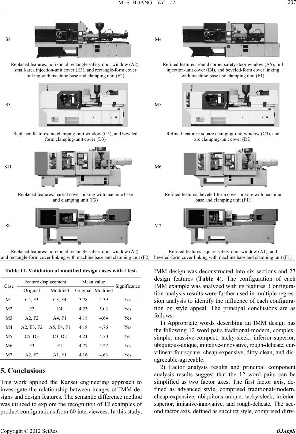 M.-S. HUANG ET AL. 207 S8 M4 Replaced features: horizontal rectangle safety-door window (A2), small-area injection-unit cover (E3), and rec tangle-form cover linking with m achine base and clampin g unit (F2) Refined features: round corner safety-door window (A5), full injection-unit cover (E4), and beveled-form cover linking with machine base a nd clamping unit (F1) S3 M5 Replaced features: no clamping-unit window (C5), and beveled form clamping-unit cover ( D3) Refined features: square clamping-unit window (C3), and arc clamping-unit cover (D2) S11 M6 Replaced features: partial cover linking with machine base and clamping unit (F3) Refined features: beveled-form cover linking with machine base and clampi n g unit (F1) S9 M7 Replaced features: horizontal rectangle safety-door window (A2), and rectangle-form cover linking with machine base and clamping unit (F2)Refined features: square safety-door window (A1), and beveled-form cover linking with machine b ase and clamping unit (F1) Table 11. Validation of modified design cases with t test. Feature displacement Mean value Case Original Modified Original Modified Significance M1 C5, F3 C3, F4 3. 78 4.39 Yes M2 E3 E4 4.23 5.03 Yes M3 A2, F2 A4, F1 4.18 4.64 Yes M4 A2, E3, F2 A5, E4, F1 4.18 4.76 Yes M5 C5, D 3 C3, D2 4.21 4.70 Yes M6 F3 F1 4.77 5.27 Yes M7 A2, F2 A1, F1 4.16 4.63 Yes 5. Conclusions This work applied the Kansei engineering approach to investigate the relationship between images of IMM de- signs and design features. The semantic difference method was utilized to explore the recognitio n of 12 examples of produ ct configu ration s from 60 interv iewees. In this stud y, IMM design was deconstructed into six sections and 27 design features (Table 4). The configuration of each IMM example was analyzed with its features. Configura- tion analysis results were further used in multiple regres- sion analysis to identify the influence of each configura- tion on style appeal. The principal conclusions are as follows. 1) Appropriate words describing an IMM design has the following 12 word pairs traditional-modern, complex- simple, massive-compact, tacky-sleek, inferior-superior, ubiquitous-unique, imitative-innovative, rough-delicate, cur- vilinear-foursquare, cheap-expensive, dirty-clean, and dis- agreeable-agreeable. 2) Factor analysis results and principal component analysis results suggest that the 12 word pairs can be simplified as two factor axes. The first factor axis, de- fined as advanced style, comprised traditional-modern, cheap-expensive, ubiquitous-unique, tacky-sleek, inferior- superior, imitative-innovative, and rough-delicate. The sec- ond factor axis, defined as succinct style, co mp ri s ed d i r ty - Copyright © 2012 SciRes. OJAppS  M.-S. HUANG ET AL. 208 clean, massive-compact, and agreeable-agreeable. These two factors account fo r 93 .5 5 % of vari ance. 3) Multiple regression analysis for features indicates that, for the advanced style, an IMM design should use a rectangular form for the clamping-unit cover and a full-cover for the injection-unit. A rectangular cover linked to the machine base at a ratio of 1 to 3 should be avoided. 4) For the succinct style, an IMM design should use a beveled form for the safety cover and a vertical rectangle for the clamping-unit cover. The following should be avoided: a horizontal rectangular form for the safety-door window; a clamping unit without a window; no cover for the injection-unit, and no cover linked to the machine base. 5) This study was conducted to support machinery configuration design as a scientific meth od incorporating human sensibilities into applied designs. Factor analysis of appropriate product style design by comparative evalu- ation using Kansei values can be utilized in generating product design strat e gi es. 6. Acknowledgements The authors would like to thank Fu Chun Shin Machin- ery Manufacture Co. Ltd. for financial support on this study. Ted Knoy is also appreciated for his editorial as- sistance. REFERENCES [1] M. Nagamachi, “Kansei Engineering: A New Ergonomic Consumer-Oriented Technology for Product Develop- ment,” International Journal Industrial Ergonomics, Vol. 15, No. 1, 1995, pp. 3-11. doi:10.1016/0169-8141(94)00052-5 [2] T. Jindo and K. Hirasago, “Application Studies to Car Interior of Kansei Engineering,” International Journal Industrial Ergonomics, Vol. 19, No. 2, 1997, pp. 105-114. doi:10.1016/S0169-8141(96)00007-8 [3] K. Nakada, “Kansei Engineering Research on the Design of Construction Machinery,” International Journal In- dustrial Ergonomics, Vol. 19, No. 2, 1997, pp. 129-146. doi:10.1016/S0169-8141(96)00009-1 [4] M. Nagamachi, “Kansei Engineering as a Powerful Con- sumer-Oriented Technology for Product Development,” Applied Ergonomics, Vol. 33, No. 3, 2002, pp. 289-294. doi:10.1016/S0003-6870(02)00019-4 [5] S. Mondragón, P. Company and M. Vergara, “Semantic Differential Applied to the Evaluation of Machine Tool Design,” International Journal Industrial Ergonomics, Vol. 35, No. 11, 2005, pp. 1021-1029. doi:10.1016/j.ergon.2005.05.001 [6] E. A. Demirtas, S. Anagun and G. Koksal, “Determina- tion of Optimal Product Styles by Ordinal Logistics Re- gression versus Conjoint Analysis for Kitchen Faucets,” International Journal Industrial Ergonomics, Vol. 39, No. 5, 2009, pp. 866-875. doi:10.1016/j.ergon.2009.06.007 [7] M.-S. Huang, H. C. Tsai and T. H. Huang, “Applying Kansei Engineering to Industrial Machinery Trade Show Booth Design,” International Journal Industrial Ergo- nomics, Vol. 41, No. 1, 2011, pp. 72-78. doi:10.1016/j.ergon.2010.10.002 [8] R. Roy, M. Goatman and K. Khangura, “User-Centric Design and Kansei Engineering,” CIRP Journal of Manu- facturing Science and Technology, Vol. 1, No. 3, 2009, pp. 172-178. doi:10.1016/j.cirpj.2008.10.007 [9] C. C. Chang and J. C. Wu, “The Underlying Factors Dominating Categorical Perception of Product Form of Mobile Phones,” International Journal Industrial Ergo- nomics, Vol. 39, No. 5, 2009, pp. 667-680. doi:10.1016/j.ergon.2009.02.012 [10] S. W. Hsiao, F. Y. Chiu and S. H. Lu, “Product-Form Design Model Based on Genetic Algorithms,” Interna- tional Journal Industrial Ergonomics, Vol. 40, No. 3, 2010, pp. 237-246. doi:10.1016/j.ergon.2010.01.009 [11] S. H. Hsu, N. C. Chuang and C. C. Chang, “A Semantic Differential Study of Designers’ and Users’ Product Form Configuration,” International Journal Industrial Ergo- nomics, Vol. 25, No. 4, 2000, pp. 375-391. doi:10.1016/S0169-8141(99)00026-8 [12] K. Jiro, “KJ Method: A Scientific Approach to Problem Solving,” Kawakita Research Institute, Tokyo, 2000. [13] C. C. Tseng, “The Application of Kansei Engineering to the Image Recognition Analysis and Computer-Aided Logo Design for Banks,” Ph.D. Thesis, National Cheng Kung University, Taiwan, 2003. [14] C. H. Wang, “A Study on the Influence of the Features of a Bicycle’s Frame Form on the Image Perception,” Mas- ter Thesis, National Cheng Kung University, Taiwan, 2003. [15] M. S. Shen, “A Study on the Combination of Multiple Kansei Words,” Master Thesis, National Yunlin Univer- sity of Science and Technology, Taiwan, 2004. [16] J. C. Jones, “Design Methods,” Van Nostrand Reinhold, London, 1992. Copyright © 2012 SciRes. OJAppS
|