Paper Menu >>
Journal Menu >>
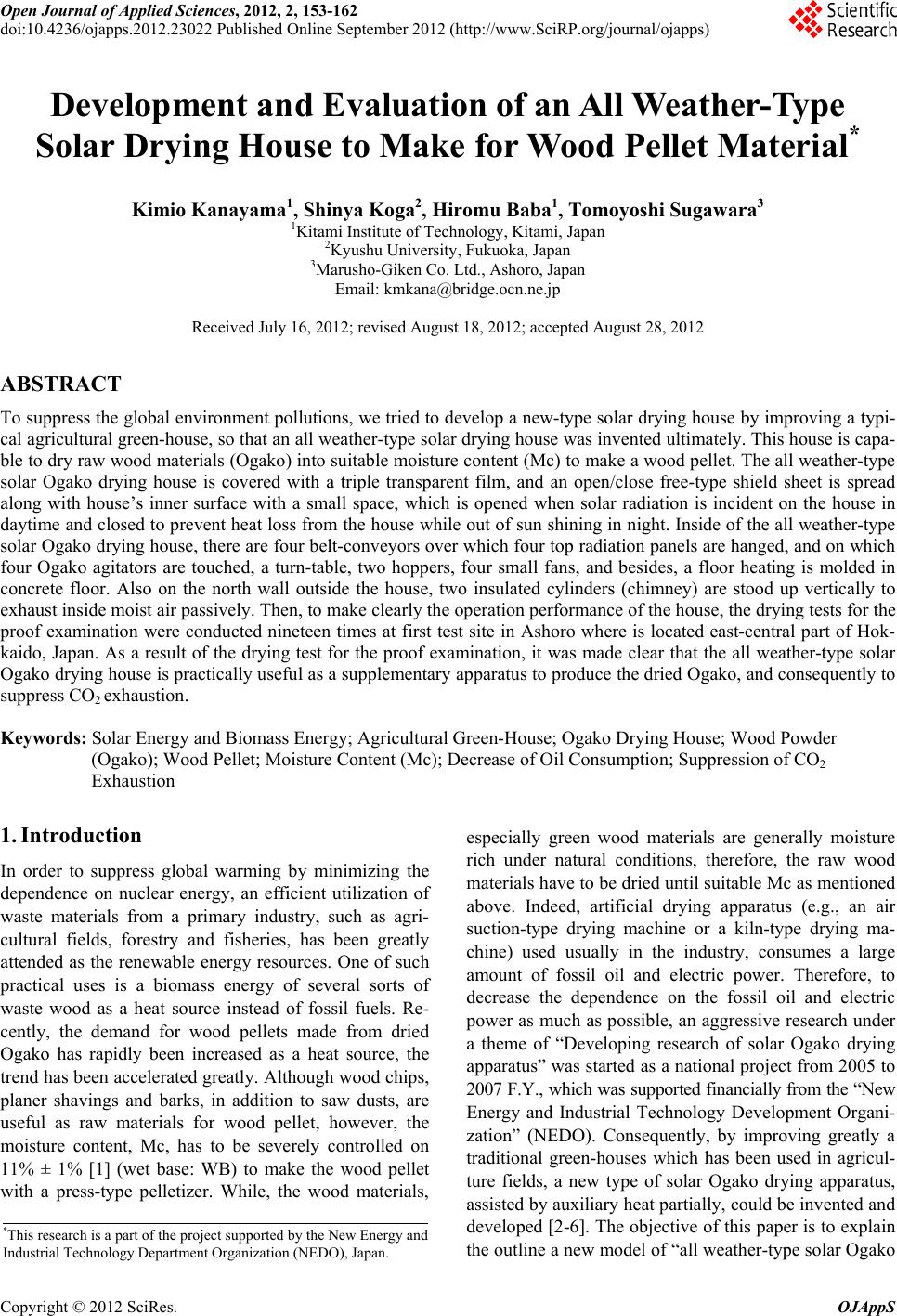 Open Journal of Applied Sciences, 2012, 2, 153-162 doi:10.4236/ojapps.2012.23022 Published Online September 2012 (http://www.SciRP.org/journal/ojapps) Development and Evaluation of an All Weather-Type Solar Drying House to Make for Wood Pellet Material* Kimio Kanayama1, Shinya Koga2, Hiromu Baba1, Tomoyoshi Sugawara3 1Kitami Institute of Technology, Kitami, Japan 2Kyushu University, Fukuoka, Japan 3Marusho-Giken Co. Ltd., Ashoro, Japan Email: kmkana@bridge.ocn.ne.jp Received July 16, 2012; revised August 18, 2012; accepted August 28, 2012 ABSTRACT To suppress the global environment pollutions, we tried to develop a new-type solar drying house by improving a typi- cal agricultural green-house, so that an all weather-type solar drying house was invented ultimately. This house is capa- ble to dry raw wood materials (Ogako) into suitable moisture content (Mc) to make a wood pellet. The all weather-type solar Ogako drying house is covered with a triple transparent film, and an open/close free-type shield sheet is spread along with house’s inner surface with a small space, which is opened when solar radiation is incident on the house in daytime and closed to prevent heat loss from the house while out of sun shining in night. Inside of the all weather-type solar Ogako drying house, there are four belt-conveyors over which four top radiation panels are hanged, and on which four Ogako agitators are touched, a turn-table, two hoppers, four small fans, and besides, a floor heating is molded in concrete floor. Also on the north wall outside the house, two insulated cylinders (chimney) are stood up vertically to exhaust inside moist air passively. Then, to make clearly the operation performance of the house, the drying tests for the proof examination were conducted nineteen times at first test site in Ashoro where is located east-central part of Hok- kaido, Japan. As a result of the drying test for the proof examination, it was made clear that the all weather-type solar Ogako drying house is practically useful as a supplementary apparatus to produce the dried Ogako, and consequently to suppress CO2 exhaustion. Keywords: Solar Energy and Biomass Energy; Agricultural Green-House; Ogako Drying House; Wood Powder (Ogako); Wood Pellet; Moisture Content (Mc); Decrease of Oil Consumption; Suppression of CO2 Exhaustion 1. Introduction In order to suppress global warming by minimizing the dependence on nuclear energy, an efficient utilization of waste materials from a primary industry, such as agri- cultural fields, forestry and fisheries, has been greatly attended as the renewable energy resources. One of such practical uses is a biomass energy of several sorts of waste wood as a heat source instead of fossil fuels. Re- cently, the demand for wood pellets made from dried Ogako has rapidly been increased as a heat source, the trend has been accelerated greatly. Although wood chips, planer shavings and barks, in addition to saw dusts, are useful as raw materials for wood pellet, however, the moisture content, Mc, has to be severely controlled on 11% ± 1% [1] (wet base: WB) to make the wood pellet with a press-type pelletizer. While, the wood materials, especially green wood materials are generally moisture rich under natural conditions, therefore, the raw wood materials have to be dried until suitable Mc as mentioned above. Indeed, artificial drying apparatus (e.g., an air suction-type drying machine or a kiln-type drying ma- chine) used usually in the industry, consumes a large amount of fossil oil and electric power. Therefore, to decrease the dependence on the fossil oil and electric power as much as possible, an aggressive research under a theme of “Developing research of solar Ogako drying apparatus” was started as a national project from 2005 to 2007 F.Y., which was supported financially from the “New Energy and Industrial Technology Development Organi- zation” (NEDO). Consequently, by improving greatly a traditional green-houses which has been used in agricul- ture fields, a new type of solar Ogako drying apparatus, assisted by auxiliary heat partially, could be invented and developed [2-6]. The objective of this paper is to explain the outline a new model of “all weather-type solar Ogako *This research is a part of the project supported by the New Energy and Industrial Technology Department Organization (NEDO), Japan. Copyright © 2012 SciRes. OJAppS 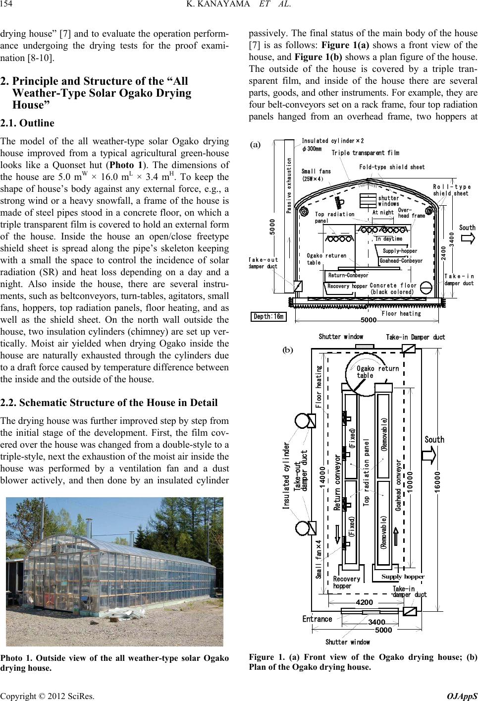 K. KANAYAMA ET AL. 154 drying house” [7] and to evaluate the operation perform- ance undergoing the drying tests for the proof exami- nation [8-10]. 2. Principle and Structure of the “All Weather-Type Solar Ogako Drying House” 2.1. Outline The model of the all weather-type solar Ogako drying house improved from a typical agricultural green-house looks like a Quonset hut (Photo 1). The dimensions of the house are 5.0 mW × 16.0 mL × 3.4 mH. To keep the shape of house’s body against any external force, e.g., a strong wind or a heavy snowfall, a frame of the house is made of steel pipes stood in a concrete floor, on which a triple transparent film is covered to hold an external form of the house. Inside the house an open/close freetype shield sheet is spread along the pipe’s skeleton keeping with a small the space to control the incidence of solar radiation (SR) and heat loss depending on a day and a night. Also inside the house, there are several instru- ments, such as beltconveyors, turn-tables, agitators, small fans, hoppers, top radiation panels, floor heating, and as well as the shield sheet. On the north wall outside the house, two insulation cylinders (chimney) are set up ver- tically. Moist air yielded when drying Ogako inside the house are naturally exhausted through the cylinders due to a draft force caused by temperature difference between the inside and the outside of the house. 2.2. Schematic Structure of the House in Detail The drying house was further improved step by step from the initial stage of the development. First, the film cov- ered over the house was changed from a double-style to a triple-style, next the exhaustion of the moist air inside the house was performed by a ventilation fan and a dust blower actively, and then done by an insulated cylinder Photo 1. Outside view of the all weather-type solar Ogako drying house. passively. The final status of the main body of the house [7] is as follows: Figure 1(a) shows a front view of the house, and Figure 1(b) shows a plan figure of the house. The outside of the house is covered by a triple tran- sparent film, and inside of the house there are several parts, goods, and other instruments. For example, they are four belt-conveyors set on a rack frame, four top radiation panels hanged from an overhead frame, two hoppers at 3400 5000 5000 2400 Insulated cylinder×2 Passiveexhaustion Fold-typeshield sheet Small fans ( 25W×4 ) Roll-type shield sheet shutter windows At night In daytime Over- head frame South Take-in damper duct Top radiation panel T ake-out d amper duct Ogakoreturen table Supply-hopper Recovery hopper Goahead-Conbeyor Concrete floor (black colored) Floor heating Depth:16m Return-Conbeyor Triple transparent film φ300mm (a) 3400 5000 10000 16000 14000 Goahead conveyor Topradiation panel (Removable) (Fixed) Returnconveyor Supplyhopper Recovery hopper Ogako return table Insulatedcylinder Take-in Damperduc t Take- out damper duct Take-in damper duct Small fan×4 Shutter window Entrance 4200 South Floor heating (Removable) (Fixed) Shutter window (b) Figure 1. (a) Front view of the Ogako drying house; (b) Plan of the Ogako drying house. Copyright © 2012 SciRes. OJAppS 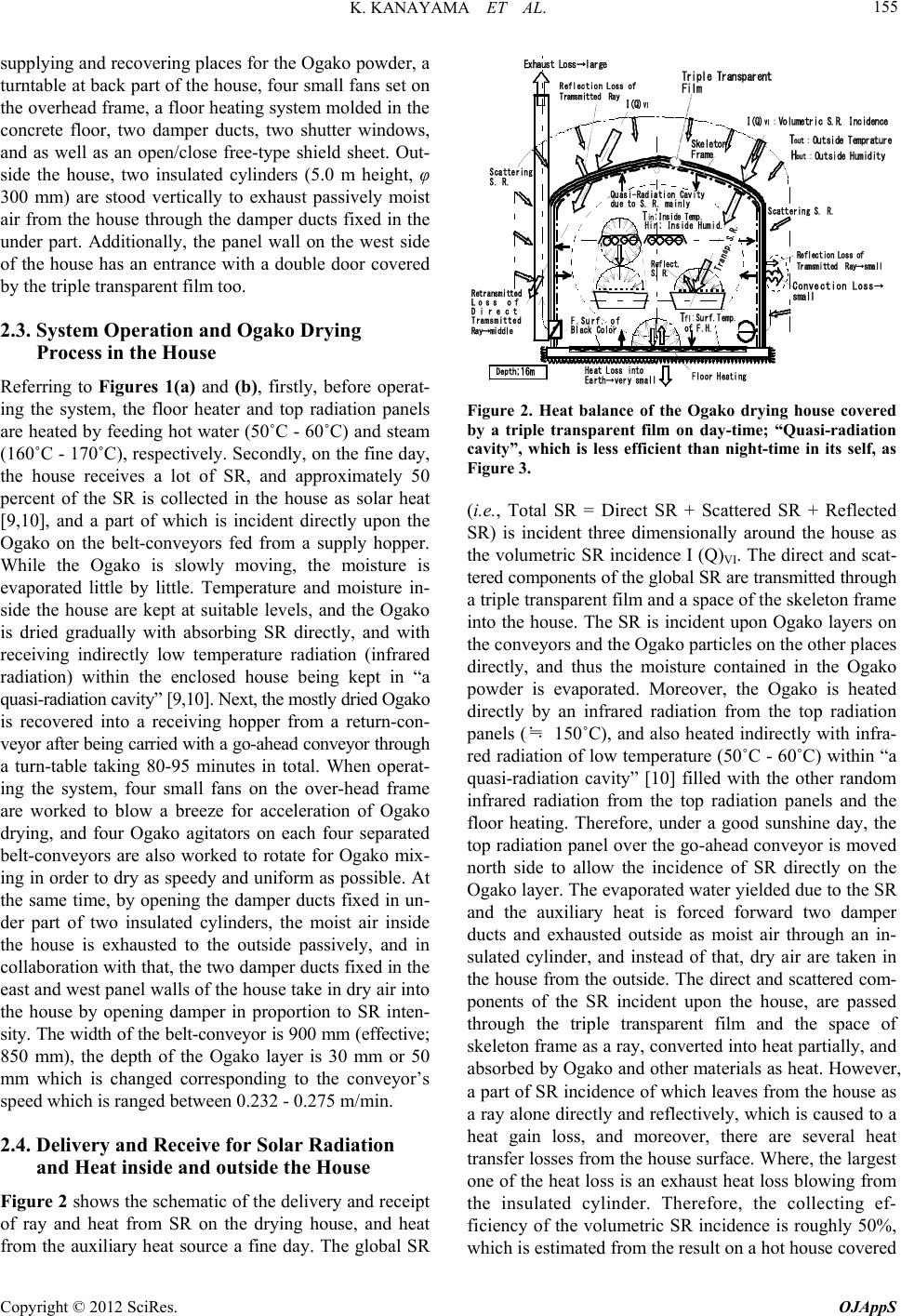 K. KANAYAMA ET AL. 155 supplying and recovering places for the Ogako powder, a turntable at back part of the house, four small fans set on the overhead frame, a floor heating system molded in the concrete floor, two damper ducts, two shutter windows, and as well as an open/close free-type shield sheet. Out- side the house, two insulated cylinders (5.0 m height, φ 300 mm) are stood vertically to exhaust passively moist air from the house through the damper ducts fixed in the under part. Additionally, the panel wall on the west side of the house has an entrance with a double door covered by the triple transparent film too. 2.3. System Operation and Ogako Drying Process in the House Referring to Figures 1(a) and (b), firstly, before operat- ing the system, the floor heater and top radiation panels are heated by feeding hot water (50˚C - 60˚C) and steam (160˚C - 170˚C), respectively. Secondly, on the fine day, the house receives a lot of SR, and approximately 50 percent of the SR is collected in the house as solar heat [9,10], and a part of which is incident directly upon the Ogako on the belt-conveyors fed from a supply hopper. While the Ogako is slowly moving, the moisture is evaporated little by little. Temperature and moisture in- side the house are kept at suitable levels, and the Ogako is dried gradually with absorbing SR directly, and with receiving indirectly low temperature radiation (infrared radiation) within the enclosed house being kept in “a quasi-radiation cavity” [9,10]. Next, the mostly dried Ogako is recovered into a receiving hopper from a return-con- veyor after being carried with a go-ahead conveyor through a turn-table taking 80-95 minutes in total. When operat- ing the system, four small fans on the over-head frame are worked to blow a breeze for acceleration of Ogako drying, and four Ogako agitators on each four separated belt-conveyors are also worked to rotate for Ogako mix- ing in order to dry as speedy and uniform as possible. At the same time, by opening the damper ducts fixed in un- der part of two insulated cylinders, the moist air inside the house is exhausted to the outside passively, and in collaboration with that, the two damper ducts fixed in the east and west panel walls of the house take in dry air into the house by opening damper in proportion to SR inten- sity. The width of the belt-conveyor is 900 mm (effective; 850 mm), the depth of the Ogako layer is 30 mm or 50 mm which is changed corresponding to the conveyor’s speed which is ranged between 0.232 - 0.275 m/min. 2.4. Delivery and Receive for Solar Radiation and Heat inside and outside the House Figure 2 shows the schematic of the delivery and receipt of ray and heat from SR on the drying house, and heat from the auxiliary heat source a fine day. The global SR Depth ;16m T in : Inside Temp. T out :Outside Temprature H out :Outside Humidity I( Q) VI :Volumetric S.R. Incidence T fl : Surf.Temp. of F.H. Quasi-Radiation Cavity due toS. R. mainly Skeleton Frame Transp.S.R. Reflection Lossof TramsmittedRay Floor Heating Convection Loss→ small Reflection Loss of Tramsmitted Ray→small Retransmitted Lossof Direct Tramsmitted Ray→middle ExhaustLoss→large F.Surf. of Black Color Triple Transparent Film Heat Lossinto Earth→very small Scattering S. R. Scattering S.R. I( Q) VI Reflect. S. R. Hin; InsideHumid. Figure 2. Heat balance of the Ogako drying house covered by a triple transparent film on day-time; “Quasi-radiation cavity”, which is less efficient than night-time in its self, as Figure 3. (i.e., Total SR = Direct SR + Scattered SR + Reflected SR) is incident three dimensionally around the house as the volumetric SR incidence I (Q)VI. The direct and scat- tered components of the global SR are transmitted through a triple transparent film and a space of the skeleton frame into the house. The SR is incident upon Ogako layers on the conveyors and the Ogako particles on the other places directly, and thus the moisture contained in the Ogako powder is evaporated. Moreover, the Ogako is heated directly by an infrared radiation from the top radiation panels (≒ 150˚C), and also heated indirectly with infra- red radiation of low temperature (50˚C - 60˚C) within “a quasi-radiation cavity” [10] filled with the other random infrared radiation from the top radiation panels and the floor heating. Therefore, under a good sunshine day, the top radiation panel over the go-ahead conveyor is moved north side to allow the incidence of SR directly on the Ogako layer. The evaporated water yielded due to the SR and the auxiliary heat is forced forward two damper ducts and exhausted outside as moist air through an in- sulated cylinder, and instead of that, dry air are taken in the house from the outside. The direct and scattered com- ponents of the SR incident upon the house, are passed through the triple transparent film and the space of skeleton frame as a ray, converted into heat partially, and absorbed by Ogako and other materials as heat. However, a part of SR incidence of which leaves from the house as a ray alone directly and reflectively, which is caused to a heat gain loss, and moreover, there are several heat transfer losses from the house surface. Where, the largest one of the heat loss is an exhaust heat loss blowing from the insulated cylinder. Therefore, the collecting ef- ficiency of the volumetric SR incidence is roughly 50%, which is estimated from the result on a hot house covered Copyright © 2012 SciRes. OJAppS 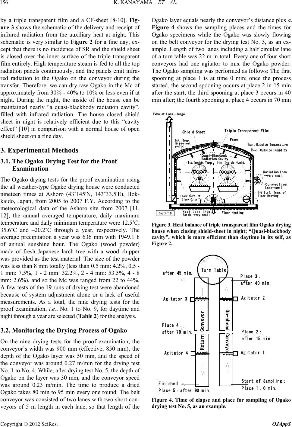 K. KANAYAMA ET AL. 156 by a triple transparent film and a CF-sheet [8-10]. Fig- ure 3 shows the schematic of the delivery and receipt of infrared radiation from the auxiliary heat at night. This schematic is very similar to Figure 2 for a fine day, ex- cept that there is no incidence of SR and the shield sheet is closed over the inner surface of the triple transparent film entirely. High temperature steam is fed to all the top radiation panels continuously, and the panels emit infra- red radiation to the Ogako on the conveyor during the transfer. Therefore, we can dry raw Ogako in the Mc of approximately from 30% - 40% to 10% or less even if at night. During the night, the inside of the house can be maintained nearly “a quasi-blackbody radiation cavity”, filled with infrared radiation. The house closed shield sheet in night is relatively efficient due to this “cavity effect” [10] in comparison with a normal house of open shield sheet on a fine day. 3. Experimental Methods 3.1. The Ogako Drying Test for the Proof Examination The Ogako drying tests for the proof examination using the all weather-type Ogako drying house were conducted nineteen times at Ashoro (43˚145'N, 143˚33.5'E), Hok- kaido, Japan, from 2005 to 2007 F.Y. According to the meteorological data of the Ashoro site from 2007 [11, 12], the annual averaged temperature, daily maximum temperature and daily minimum temperature were 12.5˚C, 35.6˚C and –20.2˚C through a year, respectively. The average precipitation a year was 636 mm with 1949.1 h of annual sunshine hour. The Ogako (wood powder) made of fresh Japanese larch tree with a wood chipper was provided as the test material. The size of the powder was less than 8 mm totally (less than 0.5 mm: 4.2%, 0.5 - 1 mm: 7.5%, 1 - 2 mm: 32.2%, 2 - 4 mm: 53.5%, 4 - 8 mm: 2.6%), and so the Mc was ranged from 22 to 44%. A few tests of the 19 runs of drying test were abandoned because of system adjustment alone or a lack of useful measurements. As a total, the nine drying tests for the proof examination, i.e., No. 1 to No. 9, for daytime and night through a year are selected (Table 2) for the analysis. 3.2. Monitoring the Drying Process of Ogako On the nine drying tests for the proof examination, the conveyor’s width was 900 mm (effective; 850 mm), the depth of the Ogako layer was 50 mm, and the speed of the conveyor was around 0.27 m/min for the drying test No. 1 to No. 4. While, after drying test No. 5, the depth of Ogako on the layer was 30 mm, and the conveyor speed was around 0.23 m/min. The time to produce a dried Ogako takes 80 min to 95 min every one round. The belt conveyor was consisted of two lanes with two short con- veyors of 5 m length in each lane, so that length of the Ogako layer equals nearly the conveyor’s distance plus α. Figure 4 shows the sampling places and the times for Ogako specimens while the Ogako was slowly flowing on the belt conveyor for the drying test No. 5, as an ex- ample. Length of two lanes including a half circular lane of a turn table was 22 m in total. Every one of four short conveyors had one agitator to mix the Ogako powder. The Ogako sampling was performed as follows: The first spooning at place 1 is at time 0 min; once the process started, the second spooning occurs at place 2 in 15 min after the start; the third spooning at place 3 occurs in 40 min after; the fourth spooning at place 4 occurs in 70 min T in :Inside Temp. T out :Outside Temperature H in: Inside Humid. H out :Outside Humidity T fl : Surf.Temp. of Floor Heating Quasi-Blackbody Radiation Cavity Frame Floor Heating Convection Loss→small Exhaust Loss→large Floor Surf. of Black Color Triple Transparent Film Heat Loss into Earth→very small ShieldSheet RadiationLoss →very small Tst:T emp. Shield -s heet (≒Tin) Depth ;16 Figure 3. Heat balance of triple transpa rent film Ogak o drying house when closing shield-sheet in night; “Quasi-blackbody cavity”, which is more efficient than daytime in its self, as Figure 2. Turn Table after45min. Place4: after 70 min.Place2: after15min. Place 3: after 40 min. Start of Sampling: Place 1:0 min. Finishe d Place5:after90 min. Return Conveyor Go-ahead Conveyor Agitator 2 Agitator 1 Agitator 3 Agitator 4 Figure 4. Time of elapse and place for sampling of Ogako drying test No. 5, as an example. Copyright © 2012 SciRes. OJAppS 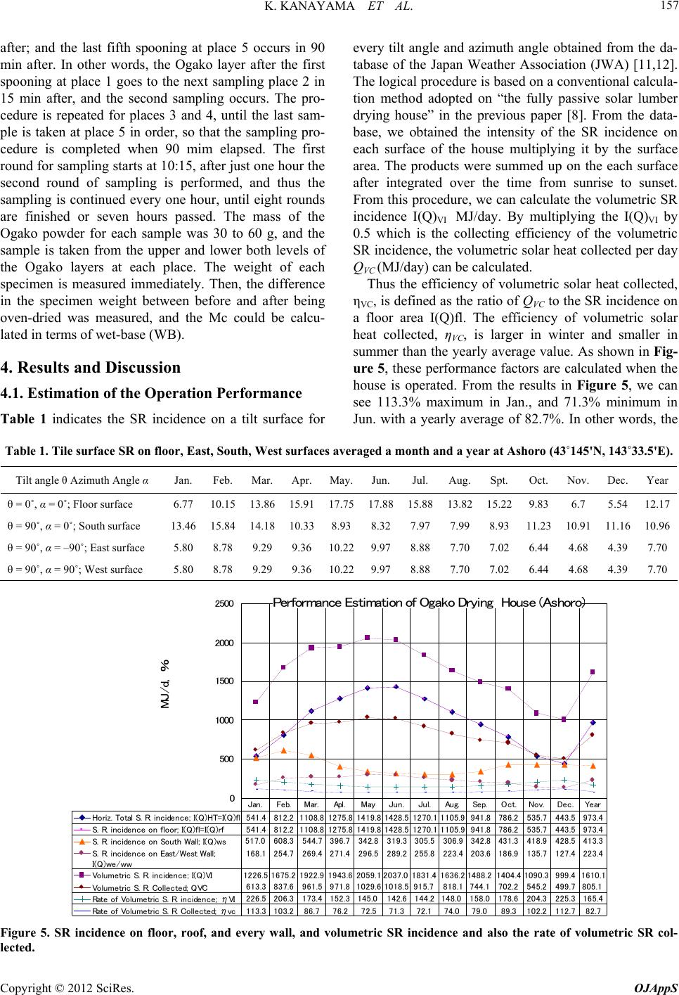 K. KANAYAMA ET AL. Copyright © 2012 SciRes. OJAppS 157 after; and the last fifth spooning at place 5 occurs in 90 min after. In other words, the Ogako layer after the first spooning at place 1 goes to the next sampling place 2 in 15 min after, and the second sampling occurs. The pro- cedure is repeated for places 3 and 4, until the last sam- ple is taken at place 5 in order, so that the sampling pro- cedure is completed when 90 mim elapsed. The first round for sampling starts at 10:15, after just one hour the second round of sampling is performed, and thus the sampling is continued every one hour, until eight rounds are finished or seven hours passed. The mass of the Ogako powder for each sample was 30 to 60 g, and the sample is taken from the upper and lower both levels of the Ogako layers at each place. The weight of each specimen is measured immediately. Then, the difference in the specimen weight between before and after being oven-dried was measured, and the Mc could be calcu- lated in terms of wet-base (WB). every tilt angle and azimuth angle obtained from the da- tabase of the Japan Weather Association (JWA) [11,12]. The logical procedure is based on a conventional calcula- tion method adopted on “the fully passive solar lumber drying house” in the previous paper [8]. From the data- base, we obtained the intensity of the SR incidence on each surface of the house multiplying it by the surface area. The products were summed up on the each surface after integrated over the time from sunrise to sunset. From this procedure, we can calculate the volumetric SR incidence I(Q)VI MJ/day. By multiplying the I(Q)VI by 0.5 which is the collecting efficiency of the volumetric SR incidence, the volumetric solar heat collected per day QVC (MJ/day) can be calculated. Thus the efficiency of volumetric solar heat collected, ηVC, is defined as the ratio of QVC to the SR incidence on a floor area I(Q)fl. The efficiency of volumetric solar heat collected, ηVC, is larger in winter and smaller in summer than the yearly average value. As shown in Fig- ure 5, these performance factors are calculated when the house is operated. From the results in Figure 5, we can see 113.3% maximum in Jan., and 71.3% minimum in Jun. with a yearly average of 82.7%. In other words, the 4. Results and Discussion 4.1. Estimation of the Operation Performance Table 1 indicates the SR incidence on a tilt surface for Table 1. Tile surface SR on floor, East, South, West surfaces averaged a month and a year at Ashoro (43˚145'N, 143˚33.5'E). Tilt angle θ Azimuth Angle α Jan. Feb. Mar.Apr.May.Jun.Jul. Aug.Spt.Oct. Nov. Dec.Year θ = 0˚, α = 0˚; Floor surface 6.77 10.15 13.86 15.91 17.75 17.88 15.8813.8215.22 9.83 6.7 5.5412.17 θ = 90˚, α = 0˚; South surface 13.46 15.84 14.18 10.338.938.327.977.998.93 11.23 10.91 11.16 10.96 θ = 90˚, α = –90˚; East surface 5.80 8.78 9.299.3610.229.97 8.88 7.70 7.02 6.44 4.68 4.397.70 θ = 90˚, α = 90˚; West surface 5.80 8.78 9.299.3610.229.97 8.88 7.70 7.02 6.44 4.68 4.39 7.70 Performance Estimation of Ogako Drying House ( Ashoro ) 0 500 1000 1500 2000 2500 MJ/d, % Horiz. Total S. R. incidence; I(Q)HT=I(Q)fl541.4812.21108.81275.81419.8 1428.51270.1 1105.9941.8786.2535.7443.5973.4 S. R. incidence on floor; I(Q)fl=I(Q)rf541.4812.21108.81275.81419.8 1428.51270.1 1105.9941.8786.2535.7443.5973.4 S. R. incidence on South Wall; I(Q)ws517.0 608.3544.7396.7342.8319.3305.5306.9342.8431.3418.9428.5413.3 S. R. incidence on East/West Wall; I(Q) w e/ww 168.1254.7 269.4271.4 296.5 289.2255.8 223.4203.6186.9 135.7 127.4223.4 Volumetric S. R. incidence; I(Q)VI1226.51675.2 1922.91943.62059.12037.0 1831.4 1636.21488.2 1404.4 1090.3 999.41610.1 Volumetric S. R. Collected; QVC613.3837.6961.5971.81029.61018.5915.7 818.1744.1 702.2545.2499.7805.1 Rate of Volumetric S. R. incidence; ηVI226.5206.3173.4152.3145.0 142.6144.2148.0 158.0 178.6204.3225.3165.4 Rate of Volumetric S. R. Collected ; η vc113.3103.286.776.272.571.372.174.0 79.0 89.3102.2112.782.7 Jan.Feb. Mar.Apl.MayJun.Jul.Aug. Sep.Oct.Nov. Dec.Year Figure 5. SR incidence on floor, roof, and every wall, and volumetric SR incidence and also the rate of volumetric SR col- lected. 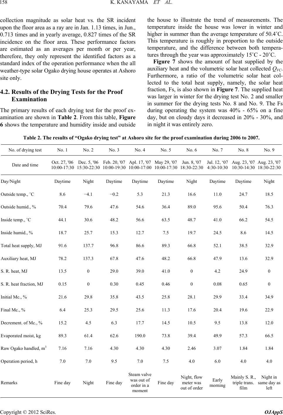 K. KANAYAMA ET AL. 158 collection magnitude as solar heat vs. the SR incident upon the floor area as a ray are in Jan. 1.13 times, in Jun., 0.713 times and in yearly average, 0.827 times of the SR incidence on the floor area. These performance factors are estimated as an averages per month or per year, therefore, they only represent the identified factors as a standard index of the operation performance when the all weather-type solar Ogako drying house operates at Ashoro site only. 4.2. Results of the Drying Tests for the Proof Examination The primary results of each drying test for the proof ex- amination are shown in Table 2. From this table, Figure 6 shows the temperature and humidity inside and outside the house to illustrate the trend of measurements. The temperature inside the house was lower in winter and higher in summer than the average temperature of 50.4˚C. This temperature is roughly in proportion to the outside temperature, and the difference between both tempera- tures through the year was approximately 15˚C - 20˚C. Figure 7 shows the amount of heat supplied by the auxiliary heat and the volumetric solar heat collected QVC. Furthermore, a ratio of the volumetric solar heat col- lected to the total heat supply, namely, the solar heat fraction, Fs, is also shown in Figure 7. The supplied heat was larger in winter for the drying test No. 2 and smaller in summer for the drying tests No. 8 and No. 9. The Fs during operating the system was 40% - 65% on a fine day, but on cloudy days it decreased in 20% - 30%, and in night it was entirely zero. Table 2. The results of “Ogako drying test” at Ashoro site for the proof examination during 2006 to 2007. No. of drying test No. 1 No. 2 No. 3 No. 4 No. 5 No. 6 No. 7 No. 8 No. 9 Date and time Oct. 27, '06 10:00-17:30 Dec. 5, '06 15:30-22:30 Feb. 20, '07 10:00-19:30 Apl. 17, '07 10:00-17:00 May 29, '07 10:00-17:30 Jun. 8, '07 18:30-22:30 Jul. 12, ‘07 4:30-10:30 Aug. 23, '07 10:30-14:30 Aug. 23, '07 18:30-22:30 Day/Night Daytime Night Daytime Daytime Daytime Night Daytime Daytime Night Outside temp., ˚C 8.6 −4.1 −0.2 5.3 21.3 16.6 11.0 24.7 18.5 Outside humid., % 70.4 79.6 47.6 54.6 36.4 89.0 95.6 50.4 76.3 Inside temp., ˚C 44.1 30.6 48.2 56.6 63.5 48.7 41.0 66.2 54.5 Inside humid., % 18.7 25.7 15.3 12.7 7.5 19.7 24.5 8.6 14.5 Total heat supply, MJ 91.6 137.7 96.8 86.6 89.3 66.8 52.1 38.5 32.9 Auxiliary heat, MJ 78.2 137.3 67.8 47.6 48.2 66.8 47.9 13.6 32.9 S. R. heat, MJ 13.5 0 29.0 39.0 41.0 0 4.2 24.9 0 S. R. heat fraction, MJ 0.15 0 0.30 0.45 0.46 0 0.08 0.65 0 Initial Mc., % 21.6 29.8 35.8 43.5 25.8 28.1 29.9 33.4 34.9 Final Mc., % 6.4 25.3 29.5 25.6 11.3 17.6 20.4 19.6 22.9 Decrement. of Mc., % 15.2 4.5 6.3 17.7 14.5 10.5 9.5 13.8 12.0 Evaporated moist, kg 89.3 61.4 62.6 190.0 73.8 39.4 49.9 57.3 66.5 Raw Ogako handled, m3 7.16 7.16 4.30 4.30 4.30 2.46 3.07 1.84 1.84 Operation period, h 7.0 7.0 9.5 7.0 7.5 4.0 6.0 4.0 4.0 Remarks Fine day Night Fine day Steam valve was out of order in a moment Fine day Night, flow meter was out of order Early morning Mainly S. R., triple trans. film Night in same day as left Copyright © 2012 SciRes. OJAppS 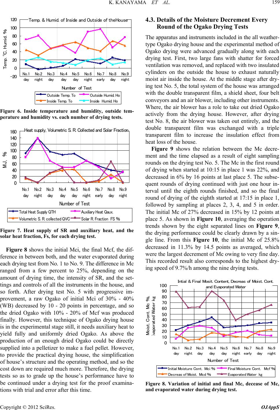 K. KANAYAMA ET AL. 159 Temp. & Humid. of Inside and Outside of theHouse -20 0 20 40 60 80 100 120 No. 1 day No. 2 night No . 3 day No. 4 day No. 5 day No. 6 night No. 7 early No. 8 day No. 9 night Number of Test Temp. ℃, Humid. % Outside Temp. To Outside Humid. Ho Inside Temp. To Inside Humid. Ho Figure 6. Inside temperature and humidity, outside tem- perature and humidity vs. each number of dry i ng te sts. Heat supply, Volumetric S. R. Collected and Solar Fractio n 0 20 40 60 80 100 120 140 160 No.1 day No.2 night No.3 day No.4 day No.5 day No.6 night No.7 early No.8 day No.9 night Number of Test MJ, % Total Heat Supply QTHAuxiliary Heat Qaux. Volumetric S. R. collected QVCSolar R. Fraction FS % Figure 7. Heat supply of SR and auxiliary heat, and the solar heat fraction, Fs, for each drying test. Figure 8 shows the initial Mci, the final Mcf, the dif- ference in between both, and the water evaporated during each drying test from No. 1 to No. 9. The difference in Mc ranged from a few percent to 25%, depending on the amount of drying time, the intensity of SR, and the set- tings and controls of all the instruments in the house, and so forth. After drying test No. 5 with progressive im- provement, a raw Ogako of initial Mci of 30% - 40% (WB) decreased by 10 - 20 points in percentage, and so the dried Ogako with 10% - 20% of Mcf was produced finally. However, this technique of Ogako drying house is in the experimental stage still, it needs auxiliary heat to yield fully and uniformly dried Ogako. As above the production of an enough dried Ogako could be directly supplied into a pelletizer to make a fuel pellet. However, to provide the practical drying house, the simplification of house’s structure and the operating method, and so the cost down are required much more. Therefore, the drying tests so as to grade up the house’s performance have to be continued under a drying test for the proof examina- tions with trial and error after this time. 4.3. Details of the Moisture Decrement Every Round of the Ogako Drying Tests The apparatus and instruments included in the all weather- type Ogako drying house and the experimental method of Ogako drying were advanced gradually along with each drying test. First, two large fans with shatter for forced ventilation was removed, and replaced with two insulated cylinders on the outside the house to exhaust naturally moist air inside the house. At the middle stage after dry- ing test No. 5, the total system of the house was arranged with the double transparent film, a shield sheet, four belt conveyors and an air blower, including other instruments. Where, the air blower has a role to take out dried Ogako actively from the drying house. However, after drying test No. 8, the air blower was taken out entirely, and the double transparent film was exchanged with a triple transparent film to increase the insulation effect from heat loss of the house. Figure 9 shows the relation between the Mc decre- ment and the time elapsed as a result of eight sampling rounds on the drying test No. 5. The Mc in the first round of drying when started at 10:15 in place 1 was 22%, and decreased in 6% by 16 points at last place 5. The subse- quent rounds of drying continued with just one hour in- terval until the eighth rounds finished, and so the final round of drying of the eighth started at 17:15 in place 1, followed by sampling at places 2, 3, 4, and 5 in order. The initial Mc of 27% decreased in 15% by 12 points at place 5. As shown in Figure 10, averaging the operation trends shown by the eight separated lines on Figure 9, the drying performance could be clearly drawn by a sin- gle line. From this Figure 10, the initial Mc of 25.8% decreased in 11.3% by 14.5 points as averaged, which were the largest decrement of Mc owing to very fine day. This recorded result also corresponds to the highest dry- ing speed of 9.7%/h among the nine drying tests. Intial & Final Mosit. Content, Decreas of Moist. Cont. and Evaporated Water 0 10 20 30 40 50 60 70 80 90 100 No .1 day No . 2 night No .3 day No .4 day No .5 day No . 6 night No .7 early No .8 day No .9 night Number of Test Moist. Cont. Mc %, E vaporated Water kg Initial Moisture Cont. Mci %Final Moisture Cont. Mcf % Decreas of Moist. Mcd %Evaporated Water kg Figure 8. Variation of initial and final Mc, decease of Mc, and evaporated water during drying test. Copyright © 2012 SciRes. OJAppS 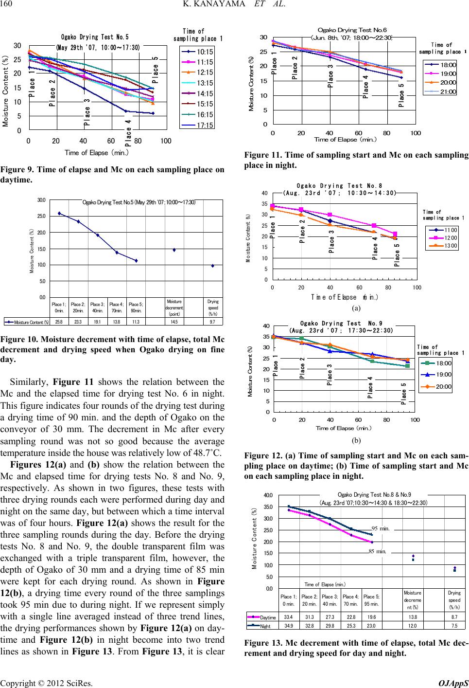 K. KANAYAMA ET AL. 160 0 5 10 15 20 25 30 020406080100 Time of Elapse (min.) Moisture Content ( % ) 10:15 11:15 12:15 13:15 14:15 15:15 16:15 17:15 OgakoDrying Test No.5 (May 29th '07, 10:00~17:30) Place1 Place 2 Place 3 Place 4 Place 5 Time of sampling place1 Figure 9. Time of elapse and Mc on each sampling place on daytime. Ogako Drying Test No.5 (May 29th '07;10:00~17:30) 0.0 5.0 10.0 15.0 20.0 25.0 30.0 M oisture Content (%) Moi sture Content (%)25.8 23.3 19.1 13.8 11.3 14.5 9.7 Place 1; 0min. Place 2; 20min. Place 3; 40mi n. Place 4; 70min. Place 5; 90mi n. Mo is tu re decr ement (point) Drying speed (%/h) Figure 10. Moisture decrement with time of elapse, total Mc decrement and drying speed when Ogako drying on fine day. Similarly, Figure 11 shows the relation between the Mc and the elapsed time for drying test No. 6 in night. This figure indicates four rounds of the drying test during a drying time of 90 min. and the depth of Ogako on the conveyor of 30 mm. The decrement in Mc after every sampling round was not so good because the average temperature inside the house was relatively low of 48.7˚C. Figures 12(a) and (b) show the relation between the Mc and elapsed time for drying tests No. 8 and No. 9, respectively. As shown in two figures, these tests with three drying rounds each were performed during day and night on the same day, but between which a time interval was of four hours. Figure 12(a) shows the result for the three sampling rounds during the day. Before the drying tests No. 8 and No. 9, the double transparent film was exchanged with a triple transparent film, however, the depth of Ogako of 30 mm and a drying time of 85 min were kept for each drying round. As shown in Figure 12(b), a drying time every round of the three samplings took 95 min due to during night. If we represent simply with a single line averaged instead of three trend lines, the drying performances shown by Figure 12(a) on day- time and Figure 12(b) in night become into two trend lines as shown in Figure 13. From Figure 13, it is clear Ogako Drying Test No.6 (Jun. 8th, '07; 18:00~22:30 ) 0 5 10 15 20 25 30 020406080100 Time of Elapse (min.) M ois t ur e C on t e n t ( % ) 18:00 19:00 20:00 21:00 Place 1 Place 2 Place 3 Place 4 Place5 Time of sampling place 1 Figure 11. Time of sampling start and Mc on each sampling place in night. Ogako Drying Test No.8 (Aug.23rd '07; 10:30~14:30) 0 5 10 15 20 25 30 35 40 020406080100 Time of Ela p se ( min. ) M o i s t ure C on t en t ( % ) 11:00 12:00 13:00 Place 1 Place2 Place 3 Place 4 Place 5 Time of sampling place 1 (a) Ogako Drying Test No.9 (Aug.23rd '07; 17:30~22:30) 0 5 10 15 20 25 30 35 40 0 20406080100 Time of Elapse (min.) Moist u r e Cont e nt ( % ) 18:00 19:00 20:00 Place1 Place 2 Place 3 Place 4 Place 5 Timeof sampling place1 (b) Figure 12. (a) Time of sampling start and Mc on each sam- pling place on daytime; (b) Time of sampling start and Mc on each sampling place in night. Ogako Drying Test No.8 & No.9 (Aug. 23rd '07;10:30~14:30 & 18:30~22:30) 0.0 5.0 10.0 15.0 20.0 25.0 30.0 35.0 40.0 Time of Elapse (min.) Moisture Content ( % ) Daytime 33.4 31.327.322.819.613.8 8.7 Ni g ht 34.932.829.825.3 23.0 12.0 7.5 Place 1; 0 min. Place 2; 20 min. Place 3; 40 min. Place 4; 70 min. Place 5; 95 min. Moisture decreme nt (%) Dr y i ng speed (%/h) 85 min. 95 min. Figure 13. Mc decrement with time of elapse, total Mc dec- rement and drying speed for day and night. Copyright © 2012 SciRes. OJAppS  K. KANAYAMA ET AL. 161 that the initial Mc of the raw Ogako on daytime was lower than that of night, and the decrement in the Mc on daytime was 13.8 points after 85 min, which was slightly higher than the 12.0 points in percentage after 95 min in night. In this case, therefore, we can result in the drying speed of 8.7%/h for the day and 7.5%/h for the night. The speed of the belt-conveyor including a turn table corresponded to 0.258 m/min for the drying time of 80 min. Connecting with this 0.244 m/min is for the drying time of 85 min and 0.232 m/min is for the drying time of 95 min. Where, depth of the raw Ogako layer on the conveyor was 30 mm. As an example of a slow drying speed, Figure 14 shows the results from Ogako drying test No. 7 with single averaged for the drying test from early cloud morning 4:30 to 10:30. The results of 9.5 points in percentage of the Mc decrement, or the drying speed of 6.0%/h obtained during 95 min. It was not so good because of cloudy sky from the early morning. Consequently, the performance factors under the good conditions could attain the drying speed of 10%/h or more, during one round as shown on the Ogako drying tests No. 5 and No. 8, because of the fine days. 5. Evaluation of the Environmental Preservation Though the total heat supply in the house is the sum of a solar heat and an auxiliary heat from fossil oil, when us- ing wood pellets as a heat source, CO2 exhaustion is con- sidered to be zero according to the international rule of carbon neutral base. Therefore, the auxiliary heat system supplied by the wood materials wholly contributes not only the reduction in the consumption of fuel oil, but also the suppression of CO2 exhaustion. As an example, an eco-feasibility study in this experi- ment is as follows: 1) Conditions of the calculation: Rate of operation of the house/year: 60% (= 8760 h × 0.6 = 5256 h) Operation hour in daytime/year*: 871.6 h Ogako Drying Test No.7 (Jul. 12nd '07; 4:30~10:30) 0 5 10 15 20 25 30 35 Time of Elaps e Moisture Content ( % ) Moisture Content ( % ) 29.928.326.322.820.49.56.0 Place 1; 0 min. Place 2; 20 min. Place 3; 40 min. Place 4; 70 min. Place 5; 95 min. Moi s t ur e decremen t (Point) Drying speed (%/h) Figure 14. Mc decrement and drying speed when Ogako drying from early cloud morn ing. Operation hour at night/year*: 4384.4 h *Operation hours for daytime and night are determined from energy balance. 2) On the daytime: Total heat supply: 11.0 MJ/h × 871.6 h = 9561.4 MJ Auxiliary heat supply: 7.14 MJ/h × 871.6 h = 6223.2 MJ Solar heat collected: 3.83 MJ/h × 871.6 h = 3338.2 MJ Ogako handling volume: 0.70 m3/h × 871.6 h = 610.1 m3 3) In night: Total heat supply: (14.9 + 0) MJ/h × 4384.4 h = 65327.6 MJ Auxiliary heat supply: 14.9 MJ/h × 4384.4 h = 65327.6 MJ Solar heat collected: 0 MJ/h × 4384.4 h = 0 MJ Ogako handling volume: 0.70 m3/h × 4384.4 h = 3069.1 m3 4) Performance factors/year: Total heat supply: (9561.4 + 65327.6) MJ = 74889.0 MJ Auxiliary heat supply: (6223.2 + 65327.6) MJ = 62550.8 MJ Solar heat collected: 3338.2 MJ + 0 = 3338.2 MJ Ogako handling volume: 610.1 m3 + 3069.1 m3 = 3679.2 m3 Solar heat fraction/year Fs: 3338.2/9561.4 0.35 35% (daytime only) Saving of A-heavy oil/year**: 74889.0 MJ/39.1 MJ × 0.8 = 2394.1 L Suppression of CO2/year***: 2394.1 L × 0.0163 kg-C/L = 39.0 kg-C = 143.1 kg-CO2 **: The value 0.8 is an efficiency of the boiler. ***: The value 0.0163 is a coefficient when converting A-oil into kg-C. That is, according to the case study as above and the experimental results from the nine drying tests for the proof examination through one year, which consist of six daytime tests and three night-time tests, the environ- mental contributions due to “all weather-type solar Ogako drying house” were as follows: 1) The solar heat fraction through the year, Fs, was 35% for daytime; 2) The savings of A-heavy oil was 2394.1 L per year, and the suppression of CO2 gas exhaustion was 143.1 kg-CO2 per year. Copyright © 2012 SciRes. OJAppS  K. KANAYAMA ET AL. Copyright © 2012 SciRes. OJAppS 162 onsumption and suppress the ex- uation on the prac- tic 7. Acknowledgements artially a result of the “New REFERENCES [1] M. Nakajima,ama and T. Suga- , K. Kanayama, H. Seto and T. Sugawara, “Com- 6. Conclusions In order to reduce oil c par haustion of carbon dioxide in the field of a forest Indus- try, on an “all weather-type solar Ogako drying house” which was invented by our research team, the drying test for the proof examination was done over nearly three years totally, and the operation performance was verified mostly. While the drying test was progressed, the drying house was improved little by little every drying test, and the operation performance was gradually raised up ac- cording to approaching the final test. From a view point of the total eval al usefulness and the environmental preservation, the drying house is expected that the performance capability might be greatly increased by improving the operational methods, the construction of the house’s formation and materials, the control of the instruments and the total system and so on. Owing to more advancing the im- provements as above on this original concept, the opera- tional and cost performances could be raised up exten- sively, so that this system could contribute toward the revival activities in this exhausted forest industry. Sub- sequently, from a view point world-widely, this might be proposed as a leading technology for the subsidiary Ogako drying apparatus, which serves as one of the ex- cellent soft technology useful to overcome this critical era for the global preservation. This developing research is p [8] Technology System Development by Utilizing Solar En- ergy” Project, from the New Energy and Industrial Tech- nology Department Organization (NEDO), Japan. On be- half of the authors, I would like to appreciate the finan- cial support, and also I would like to say a lot of thanks for all staffs at the University, the Institute and the Com- pany for their collaboration. A. Yaegashi, Z. Komiy wara, “Introduction of Solar Ogako Drying Apparatus Created at Ashoro,” Proceedings of the 18th Symposium on Engineering in Cold Climate, Sapporo, 2006, pp. 36-38. [2] H. Baba ison between Calculations and Experiments for a Solar Ogako-Drying and a Solar Lumber Drying,” Proceedings of JSES/JWEA Joint Conference, Makuhari, Chiba, 2006, pp. 313-316. [3] S. Koga, S. Osakis, M. Nakajima, A. Yaegashi, Z. Komi- yama, T. Sugawara, H. Baba and K. Kanayama, “Drying of Japanese Larch Ogako for Wood Pellet in the Im- proved Green House with Continuous Drying Apparatus,” Proceedings of JSES/JWEA Joint Conference, Makuhari, Chiba, pp. 317-322. [4] H. Baba, K. Kanayama, T. Sugawara, M. Nakajima and S. Koga, “Development of a Continuous Ogako-Drying Ap- paratus Using Belt Conveyor in an Improved Green- House,” Proceedings of International Conference of Re- newable Energy, Makuhari, Chiba, 2006, pp. 596-599. [5] S. Koga, K. Kanayama, H. Baba, H. Seto, T. Sugawara, M. Nakajima, A. Yaegashi and Z. Komiyama, “Develop- ing Research on an All-Weather Solar Ogako Drying House―On the Basis of Drying Results in the Daytime and Night-Time,” Proceedings of JSES/JWEA Joint Con- ference, Sapporo, pp. 181-184. [6] S. Koga, K. Kanayama, H. Baba, T. Sugawara, M. Naka- jima, A. Yaegashi and Z. Komiyama, “Development of All-Weather Type Solar Dryer for Wood Pellet Material,” Proceedings of International Conference Renewable En- ergy, Busan, 2008, pp. 308-310. [7] T. Sugawara, K. Kanayama, S. Sotoda, K. Sotoda, H. Baba, K. Seto, K. Shibuya, T. Tate, S. Koga, N. Nakajima, A. Yaegashi and Z. Komiyama, “All Weather Passive-Type Solar Ogako Drying House,” US Patent No. 7681326, 2007. K. Kanayama, H. Baba, S. Koga and T. Sugawara, “De- veloping Research on a Fully Passive Solar Lumber Dry- ing Apparatus―Creation of a New Concept and Establish- ment of a Soft Technology,” Current Applied Physics, Vol. 10, No. 2, 2010, pp. S249-S253. doi: 10.1016/j.cap.2009.11.030 [9] K. Kanayama, “History of Development Research and Status Qou, and Future of the New Developing Research on the Solar Wood Material’s Drying Technology,” Pro- ceedings JSES/JWEA Joint Conference, Wakkanai, 2011, pp. 1-7. [10] K. Kanayama, S. Koga. H. Baba and T. Sugawara, “An Opaque Solar Lumber Drying House Covered by a Com- posite Surface, In: E. B. Babatunde, Ed., Solar Radiation, Intech Open Access Publisher, Croatia, 2012, pp. 399- 418. [11] http://www.jma.go.jp/jma/menu/report.html [12] Japan Weather Association (JWA), MONSOLA05 (801), “NEDO’s Data Map of All the Country,” Ashoro, 1997, p. 110. |