Paper Menu >>
Journal Menu >>
 Circuits and Systems, 2010, 1, 1-4 doi:10.4236/cs.2010.11001 Published Online July 2010 (http://www.SciRP.org/journal/cs) Copyright © 2010 SciRes. CS Two Simple Analog Multiplier Based Linear VCOs Using a Single Current Feedback Op-Amp Data Ram Bhaskar1, Raj Senani2*, Abdhesh Kumar Singh3, Shanti Swarup Gupta4 1Department of Electronics and Communication Engineering, Faculty of Engineering a nd Techn ol o gy, Jamia Millia Islamia, New Delhi, India 2Division of Electroni cs a nd C om muni cation Engineeri n g , Netaji Subhas Institute of Technology, Azad Hind Fauj Marg, New Delhi, India 3Electronics and Communication Engineering Department, ITS Engineering College, Greater Noida, India 4Ministry of Commerce and Industry, Government of India, New Delhi, India E-mail: bhaskar.ec@jmi.ac.in, senani@nsit.ac.in, abdheshks@yahoo.com, ss.gupta@nic.in Received February 27, 2010; revised March 29, 2010; accepted April 5, 2010 Abstract Two simple voltage-controlled-oscillators (VCO) with linear tuning laws employing only a single current feedback operational amplifier (CFOA) in conjunction with two analog multipliers (AM) have been highlighted. The workability of the presented VCOs has been demonstrated by experimental results based upon AD844 type CFOAs and AD534 type AMs. Keywords: Voltage-Controlled Oscillators, Current Feedback Op-Amps, Current-Mode Circuits, Analog Multipliers 1. Introduction Although a number of new building blocks and circuit concepts related to current-mode circuits have been inve- stigated in recent literature [1-3], the use of current feed- back operational amplifiers (CFOAs) as an alternative to the traditional voltage-mode op-amps (VOA), has attracted considerable attention (see [4-7] and the references cited therein) in various instrumentation, sig- nal processing and signal generation applications due to their commercial availability as off-the-shelf ICs as well as due to the well known advantages offered by CFOAs over the VOAs. Because of these reasons, use of CFOAs has been extensively investigated in realizing oscillators, for instance, see [6,8-11] and the references cited therein. Although, a variety of CFOAs are available from various manufacturers, AD844 (from Analog Devices) which contains a CCII+ followed by a voltage buffer is particu- larly flexible and popular due to the availability of z-ter- minal of the CCII+ therein as an externally accessible lead which permits AD844 to be used as a CCII+ (one AD844) or as CCII- (employing two AD844s) or as a general 4-terminal building block [6]. Voltage-Controlled Oscillators (VCO) are important building blocks in several instrumentation, electronic and communication systems, such as in function generators, in production of electronic music to generate variable tones, in phase locked loops and in frequency synthesiz- ers [12-17]. A known method of realizing VCOs is to devise an RC-active oscillator configuration with two analog mul- tipliers (AM) appropriately embedded to enable indep- endent control of the oscillation frequency through an external control voltage VC applied as a common multip- licative input to both the multipliers. When two AMs are appropriately embedded in such a configuration, this te- chnique gives rise to a linear tuning law of the form C Vf 0 (1) Based upon this approach, a number of VCO configu- rations have been proposed by various researchers in the past [12,14-17] employing traditional VOAs and AMs. A family of eight, CFOA-based linear VCOs of the above kind has recently been presented in [18]; however, all the circuits presented therein require two CFOAs al- ong with two AMs. The main object of this communica- tion is to highlight two simple linear VCOs of the above kind, which are realizable with only a single CFOA along with two AMs. Experimental results using AD844 CFOAs have been given and the advantages of the new 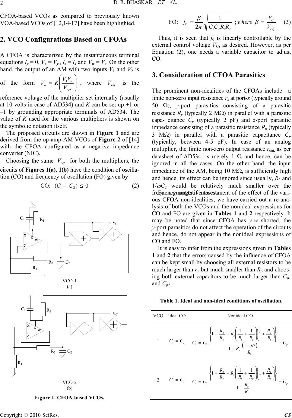 D. R. BHASKAR ET AL. Copyright © 2010 SciRes. CS 2 CFOA-based VCOs as compared to previously known VOA-based VCOs of [12,14-17] have been highlighted. 2. VCO Configurations Based on CFOAs A CFOA is characterized by the instantaneous terminal equations Iy = 0, Vx = Vy , Iz = Ix and Vw = Vz. On the other hand, the output of an AM with two inputs V1 and V2 is of the form ref oV VV KV 21 , where ref V is the reference voltage of the multiplier set internally (usually at 10 volts in case of AD534) and K can be set up +1 or –1 by grounding appropriate terminals of AD534. The value of K used for the various multipliers is shown on the symbolic notation itself. The proposed circuits are shown in Figure 1 and are derived from the op-amp-AM VCOs of Figure 2 of [14] with the CFOA configured as a negative impedance converter (NIC). Choosing the same ref V for both the multipliers, the circuits of Figures 1(a), 1(b) have the condition of oscilla- tion (CO) and frequency of oscillation (FO) given by CO: 0)( 21 CC (2) C V x y z C1 C2 2 R 1 R w 1 R VCO-1 (a) C V x y z C1 C2 2 R w 1 R R1 VCO-2 (b) Figure 1. CFOA-based VCOs. FO: ref C V V where RRCC f ; 1 22121 0 (3) Thus, it is seen that f0 is linearly controllable by the external control voltage VC, as desired. However, as per Equation (2), one needs a variable capacitor to adjust CO. 3. Consideration of CFOA Parasitics The prominent non-idealities of the CFOAs include―a finite non-zero input resistance rx at port-x (typically around 50 ), y-port parasitics consisting of a parasitic resistance Ry (typically 2 M) in parallel with a parasitic capa- citance Cy (typically 2 pF) and z-port parasitic impedance consisting of a parasitic resistance Rp (typically 3 M) in parallel with a parasitic capacitance Cp (typically, between 4-5 pF). In case of an analog multiplier, the finite non-zero output resistance rout, as per datasheet of AD534, is merely 1 and hence, can be ignored in all the cases. On the other hand, the input impedance of the AM, being 10 M, is sufficiently high and hence, its effect can be ignored since usually, R2 and 1/ C2 would be relatively much smaller over the frequency range of interest. For a quantitative assessment of the effect of the vari- ous CFOA non-idealities, we have carried out a re-ana- lysis of both the VCOs and the nonideal expressions for CO and FO are given in Tables 1 and 2 respectively. It may be noted that since CFOA has y-w shorted, the y-port parasitics do not affect the operation of the circuits and hence, do not appear in the nonideal expressions of CO and FO. It is easy to infer from the expressions given in Tables 1 and 2 that the errors caused by the influence of CFOA can be kept small by choosing all external resistors to be much larger than rx but much smaller than Rp and choos- ing both external capacitors to be much larger than Cp1 and Cp2. Table 1. Ideal and non-ideal conditions of oscillation. VCOIdeal CONonideal CO 1 21 CC p x p x pC R R R R RR R R R CC 1 2 1 2 1 2 21 1 1 1 11 1 2 21 CC p x p x pC R R R R RR R R R CC 1 1 2 1 2 21 1 1 11 1 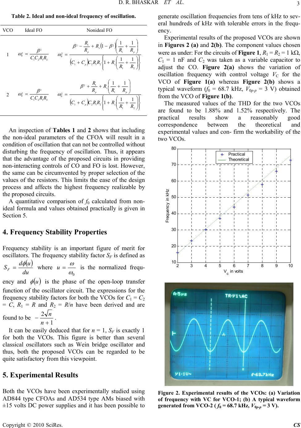 D. R. BHASKAR ET AL. Copyright © 2010 SciRes. CS 3 Table 2. Ideal and non-ideal frequency of osc illation. VCO Ideal FO Nonideal FO 1 2121 2 2 0RRCC 21 2121 1 2 1 2 2 011 1 11 1 RR RRRCCC RR R R R xp p x p 2 2121 2 2 0RRCC 21 2121 1 1 2 2 011 1 11 RR RRRCCC RR R R R xp p x p An inspection of Tables 1 and 2 shows that including the non-ideal parameters of the CFOA will result in a condition of oscillation that can not be controlled without disturbing the frequency of oscillation. Thus, it appears that the advantage of the proposed circuits in providing non-interacting controls of CO and FO is lost. However, the same can be circumvented by proper selection of the values of the resistors. This limits the ease of the design process and affects the highest frequency realizable by the proposed circuits. A quantitative comparison of f0 calculated from non- ideal formula and values obtained practically is given in Section 5. 4. Frequency Stability Properties Frequency stability is an important figure of merit for oscillators. The frequency stability factor SF is defined as du ud SF where 0 u is the normalized frequ- ency and u is the phase of the open-loop transfer function of the oscillator circuit. The expressions for the frequency stability factors for both the VCOs for C1 = C2 = C, R1 = R and R2 = R/n have been derived and are found to be 1 2 n n. It can be easily deduced that for n = 1, SF is exactly 1 for both the VCOs. This figure is better than several classical oscillators such as Wein bridge oscillator and thus, both the proposed VCOs can be regarded to be quite satisfactory from this viewpoint. 5. Experimental Results Both the VCOs have been experimentally studied using AD844 type CFOAs and AD534 type AMs biased with ±15 volts DC power supplies and it has been possible to generate oscillation frequencies from tens of kHz to sev- eral hundreds of kHz with tolerable errors in the frequ- ency. Experimental results of the proposed VCOs are shown in Figures 2 (a) and 2(b). The component values chosen were as under: For the circuits of Figure 1, R1 = R2 = 1 k, C1 = 1 nF and C2 was taken as a variable capacitor to adjust the CO. Figure 2(a) shows the variation of oscillation frequency with control voltage VC for the VCO of Figure 1(a) whereas Figure 2(b) shows a typical waveform (f0 = 68.7 kHz, V0p-p = 3 V) obtained from the VCO of Figure 1(b). The measured values of the THD for the two VCOs are found to be 1.88% and 1.52% respectively. The practical results show a reasonably good correspondence between the theoretical and experimental values and con- firm the workability of the two VCOs. 23 4 5 67 8 910 10 20 30 40 50 60 70 80 V c in volts Frequenc y i n kHz Practical Theoretical Figure 2. Experimental results of the VCOs: (a) Variation of frequency with VC for VCO-1; (b) A typical waveform generated from VCO-2 ( f0 = 68.7 kHz, V0p-p = 3 V). 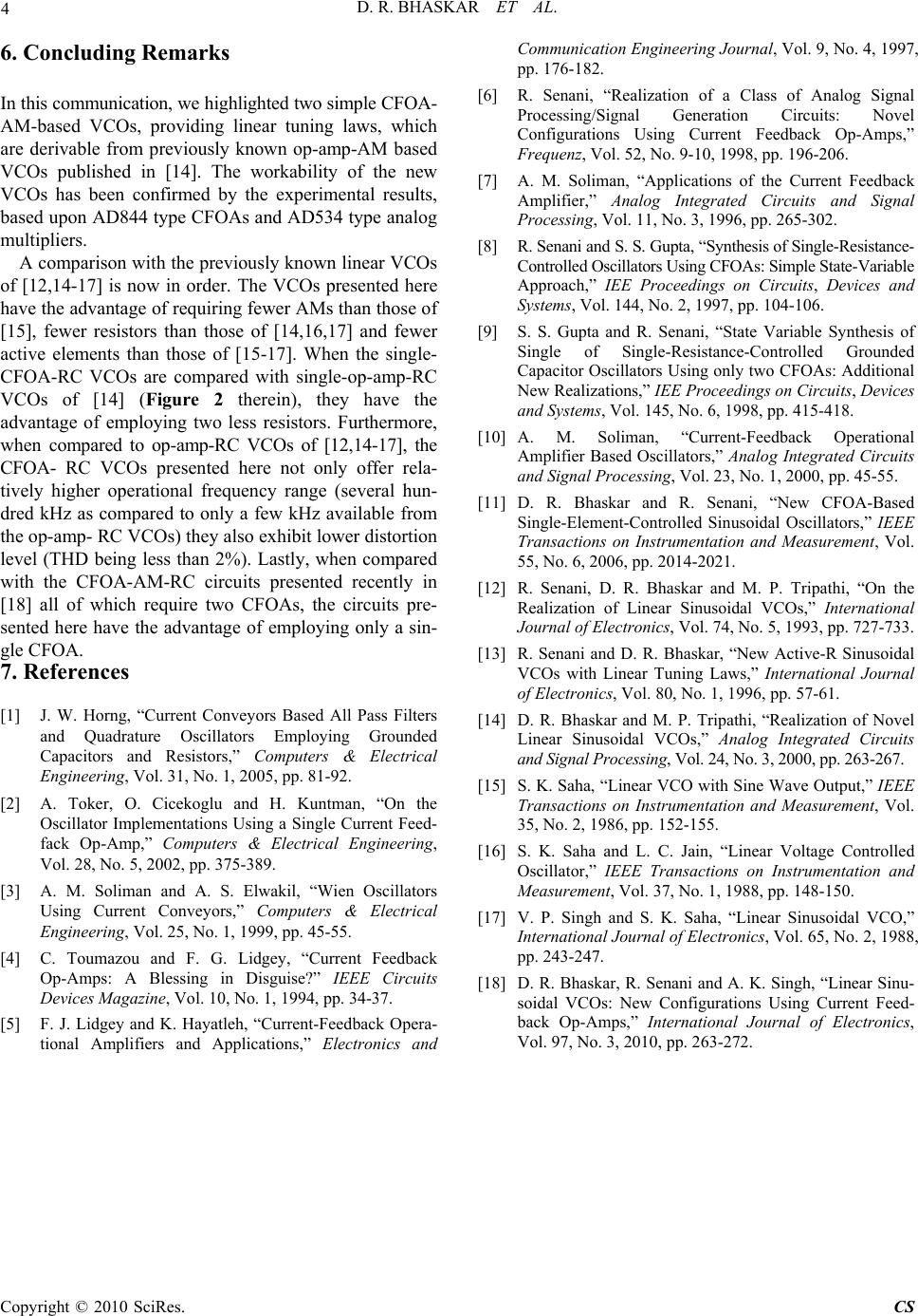 D. R. BHASKAR ET AL. Copyright © 2010 SciRes. CS 4 6. Concluding Remarks In this communication, we highlighted two simple CFOA- AM-based VCOs, providing linear tuning laws, which are derivable from previously known op-amp-AM based VCOs published in [14]. The workability of the new VCOs has been confirmed by the experimental results, based upon AD844 type CFOAs and AD534 type analog multipliers. A comparison with the previously known linear VCOs of [12,14-17] is now in order. The VCOs presented here have the advantage of requiring fewer AMs than those of [15], fewer resistors than those of [14,16,17] and fewer active elements than those of [15-17]. When the single- CFOA-RC VCOs are compared with single-op-amp-RC VCOs of [14] (Figure 2 therein), they have the advantage of employing two less resistors. Furthermore, when compared to op-amp-RC VCOs of [12,14-17], the CFOA- RC VCOs presented here not only offer rela- tively higher operational frequency range (several hun- dred kHz as compared to only a few kHz available from the op-amp- RC VCOs) they also exhibit lower distortion level (THD being less than 2%). Lastly, when compared with the CFOA-AM-RC circuits presented recently in [18] all of which require two CFOAs, the circuits pre- sented here have the advantage of employing only a sin- gle CFOA. 7. References [1] J. W. Horng, “Current Conveyors Based All Pass Filters and Quadrature Oscillators Employing Grounded Capacitors and Resistors,” Computers & Electrical Engineering, Vol. 31, No. 1, 2005, pp. 81-92. [2] A. Toker, O. Cicekoglu and H. Kuntman, “On the Oscillator Implementations Using a Single Current Feed- fack Op-Amp,” Computers & Electrical Engineering, Vol. 28, No. 5, 2002, pp. 375-389. [3] A. M. Soliman and A. S. Elwakil, “Wien Oscillators Using Current Conveyors,” Computers & Electrical Engineering, Vol. 25, No. 1, 1999, pp. 45-55. [4] C. Toumazou and F. G. Lidgey, “Current Feedback Op-Amps: A Blessing in Disguise?” IEEE Circuits Devices Magazine, Vol. 10, No. 1, 1994, pp. 34-37. [5] F. J. Lidgey and K. Hayatleh, “Current-Feedback Opera- tional Amplifiers and Applications,” Electronics and Communication Engineering Journal, Vol. 9, No. 4, 1997, pp. 176-182. [6] R. Senani, “Realization of a Class of Analog Signal Processing/Signal Generation Circuits: Novel Configurations Using Current Feedback Op-Amps,” Frequenz, Vol. 52, No. 9-10, 1998, pp. 196-206. [7] A. M. Soliman, “Applications of the Current Feedback Amplifier,” Analog Integrated Circuits and Signal Processing, Vol. 11, No. 3, 1996, pp. 265-302. [8] R. Senani and S. S. Gupta, “Synthesis of Single-Resistance- Controlled Oscillators Using CFOAs: Simple State-Variable Approach,” IEE Proceedings on Circuits, Devices and Systems, Vol. 144, No. 2, 1997, pp. 104-106. [9] S. S. Gupta and R. Senani, “State Variable Synthesis of Single of Single-Resistance-Controlled Grounded Capacitor Oscillators Using only two CFOAs: Additional New Realizations,” IEE Proceedings on Circuits, Devices and Systems, Vol. 145, No. 6, 1998, pp. 415-418. [10] A. M. Soliman, “Current-Feedback Operational Amplifier Based Oscillators,” Analog Integrated Circuits and Signal Processing, Vol. 23, No. 1, 2000, pp. 45-55. [11] D. R. Bhaskar and R. Senani, “New CFOA-Based Single-Element-Controlled Sinusoidal Oscillators,” IEEE Transactions on Instrumentation and Measurement, Vol. 55, No. 6, 2006, pp. 2014-2021. [12] R. Senani, D. R. Bhaskar and M. P. Tripathi, “On the Realization of Linear Sinusoidal VCOs,” International Journal of Electronics, Vol. 74, No. 5, 1993, pp. 727-733. [13] R. Senani and D. R. Bhaskar, “New Active-R Sinusoidal VCOs with Linear Tuning Laws,” International Journal of Electronics, Vol. 80, No. 1, 1996, pp. 57-61. [14] D. R. Bhaskar and M. P. Tripathi, “Realization of Novel Linear Sinusoidal VCOs,” Analog Integrated Circuits and Signal Processing, Vol. 24, No. 3, 2000, pp. 263-267. [15] S. K. Saha, “Linear VCO with Sine Wave Output,” IEEE Transactions on Instrumentation and Measurement, Vol. 35, No. 2, 1986, pp. 152-155. [16] S. K. Saha and L. C. Jain, “Linear Voltage Controlled Oscillator,” IEEE Transactions on Instrumentation and Measurement, Vol. 37, No. 1, 1988, pp. 148-150. [17] V. P. Singh and S. K. Saha, “Linear Sinusoidal VCO,” International Journal of Electronics, Vol. 65, No. 2, 1988, pp. 243-247. [18] D. R. Bhaskar, R. Senani and A. K. Singh, “Linear Sinu- soidal VCOs: New Configurations Using Current Feed- back Op-Amps,” International Journal of Electronics, Vol. 97, No. 3, 2010, pp. 263-272. |