Int. J. Communications, Network and System Sciences, 2010, 3, 593-601
doi:10.4236/ijcns.2010.37079 Published Online July 2010 (http://www.SciRP.org/journal/ijcns/).
Copyright © 2010 SciRes. IJCNS
Design and Analysis of a Multiple-Input Receiver for Mimo
Wireless Applications
Constantinos Votis, Panos Kostarakis
Physics Department, University of Ioannina, Panepistimioupolis, Ioannina, Greece
E-mail: kvotis@grads.uoi.gr, kostarakis@uoi.gr
Received April 21, 2010; revised May 28, 2010; accepted July 1, 2010
Abstract
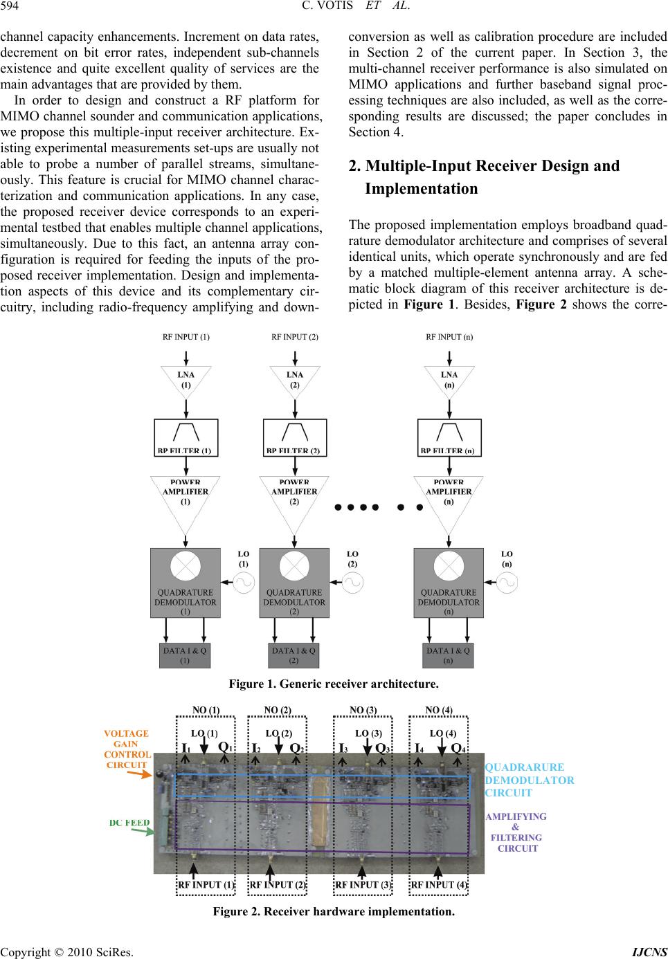
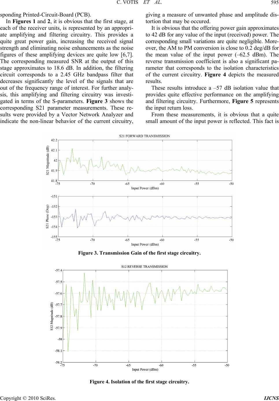
In this article, we present multiple-input receiver architecture for (Multiple-Input Multiple-Output) MIMO
wireless communication applications. The proposed implementation is provided by a defined number of
identical receiver units that are fed by a RF modulated signal on specific carrier frequency, power strength
and initial phase. These units carry out the corresponding amplification, filtering and demodulation proce-
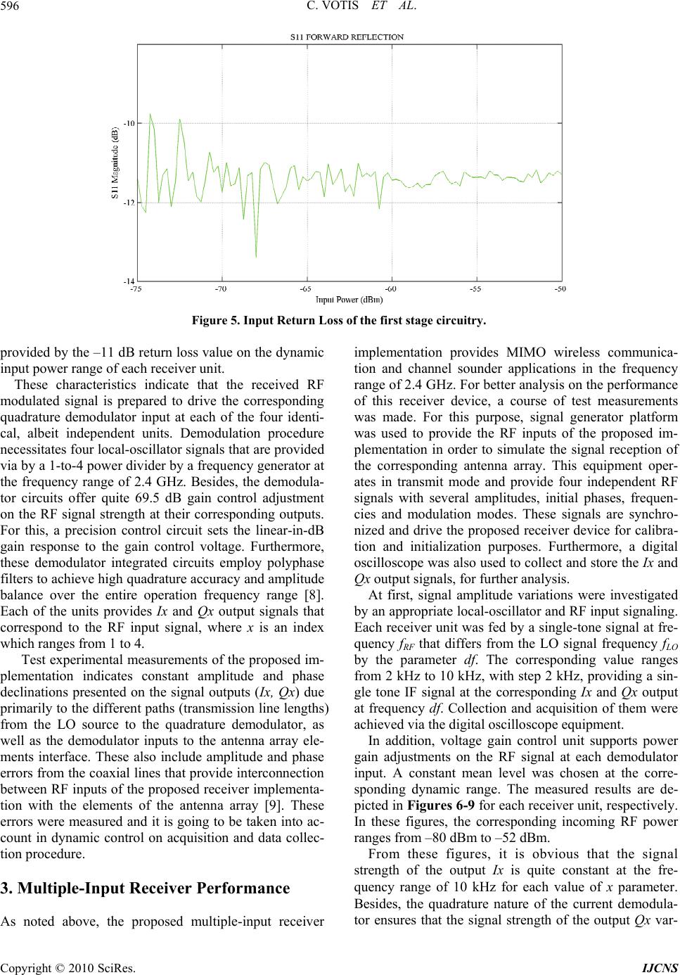
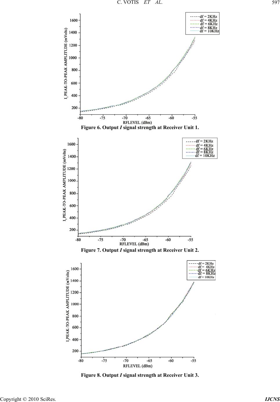
dures. Details on design and implementation of this Printed-Circuit-Board are introduced and further dis-
cussed. Experimental results are also presented, allowing the validation of investigation on the performance
of the current receiver architecture. Besides, these measurements indicate that the proposed device, combin-
ing with a suitable antenna array, provides a versatile receiver platform for baseband signal processing. The
incoming RF modulated signals have frequencies on the range of 2.4 GHz, several phases, magnitudes and
modulation modes. From these, it seems that the proposed receiver implementation supports MIMO commu-
nication and multiple port channel characterization applications at 2.4 GHz ISM (Industrial, Scientific and
Medical) band.
Keywords: Channel Sounder, MIMO Systems, Baseband Processing
1. Introduction
Modern wireless communication systems continue to
push for wider bandwidth capabilities, higher data rates
and better quality of services. Scientific and engineering
community provides a number of novel techniques and
methods to meet these requirements. One of them is
called Multiple-Input Multiple-Output (MIMO) archi-
tecture that could exploit the capacity of a wireless com-
munication channel [1-3]. Using multiple antenna ele-
ments on both the transmitter and receiver ends offers
significant capacity enhancement on radio propagation
applications. In order to achieve this benefit, appropriate
design aspects on such systems have to be taken into
account. It is obvious that a receiver device with multiple
input ports is mainly required. Furthermore, appropriate
synchronization and data acquisition procedures have to
be supported by this device in order to collect and record
the data transmission streams from each sub-channel at
any scattering radio propagation environment.
The efficiency of such systems depends on several
performance and channel parameters. One of them is
referred to the profound knowledge of the time-variant
radio channel in various indoor or outdoor environments.
Devices that could provide knowledge of the wireless
channel status are referred as channel sounding systems.
Furthermore, several multiplexing techniques are applied
to these systems for channel estimation purposes. Time,
frequency, code division multiplexing and hybrid meth-
ods are mainly used in these applications [4,5]. Generally,
these devices improve MIMO system performance and
offer crucial assumptions that provide a resource for
channel model developments.
In addition, the hardware is crucial for the perform-
ance of such MIMO systems. Resolution accuracy and
capability are dominated by the corresponding strategy
adopted for the channel sounder and communication ap-
plications. In particular, the choice of the receiver archi-
tecture indicates the method of channel acquisition and
estimation, as well as the efficiency of the MIMO com-
munication system. More precisely, fully switched, semi-
switched and parallel transmission are the main tech-
niques that supports channel characterization applica-
tions, using one or a combination of the multiplexing
methods (TDM, FDM, CDM), each with different ad-
vantages and drawbacks.
These methods also support MIMO communication
systems, providing transmit and receive diversity and
C. VOTIS ET AL.
Copyright © 2010 SciRes. IJCNS
594
channel capacity enhancements. Increment on data rates,
decrement on bit error rates, independent sub-channels
existence and quite excellent quality of services are the
main advantages that are provided by them.
In order to design and construct a RF platform for
MIMO channel sounder and communication applications,
we propose this multiple-input receiver architecture. Ex-
isting experimental measurements set-ups are usually not
able to probe a number of parallel streams, simultane-
ously. This feature is crucial for MIMO channel charac-
terization and communication applications. In any case,
the proposed receiver device corresponds to an experi-
mental testbed that enables multiple channel applications,
simultaneously. Due to this fact, an antenna array con-
figuration is required for feeding the inputs of the pro-
posed receiver implementation. Design and implementa-
tion aspects of this device and its complementary cir-
cuitry, including radio-frequency amplifying and down-
conversion as well as calibration procedure are included
in Section 2 of the current paper. In Section 3, the
multi-channel receiver performance is also simulated on
MIMO applications and further baseband signal proc-
essing techniques are also included, as well as the corre-
sponding results are discussed; the paper concludes in
Section 4.
2. Multiple-Input Receiver Design and
Implementation
The proposed implementation employs broadband quad-
rature demodulator architecture and comprises of several
identical units, which operate synchronously and are fed
by a matched multiple-element antenna array. A sche-
matic block diagram of this receiver architecture is de-
picted in Figure 1. Besides, Figure 2 shows the corre-
Figure 1. Generic receiver architecture.
QUADRARURE
DEMODULATOR
CIRCUIT
Figure 2. Receiver hardware implementation.
C. VOTIS ET AL.595
sponding Printed-Circuit-Board (PCB).
In Figures 1 and 2, it is obvious that the first stage, at
each of the receiver units, is represented by an appropri-
ate amplifying and filtering circuitry. This provides a
quite great power gain, increasing the received signal
strength and eliminating noise enhancements as the noise
figures of these amplifying devices are quite low [6,7].
The corresponding measured SNR at the output of this
stage approximates to 18.6 dB. In addition, the filtering
circuit corresponds to a 2.45 GHz bandpass filter that
decreases significantly the level of the signals that are
out of the frequency range of interest. For further analy-
sis, this amplifying and filtering circuitry was investi-
gated in terms of the S-parameters. Figure 3 shows the
corresponding S21 parameter measurements. These re-
sults were provided by a Vector Network Analyzer and
indicate the non-linear behavior of the current circuitry,
giving a measure of unwanted phase and amplitude dis-
tortion that may be occured.
It is obvious that the offering power gain approximates
to 42 dB for any value of the input (received) power. The
corresponding small variations are quite negligible. More-
over, the AM to PM conversion is close to 0.2 deg/dB for
the mean value of the input power (62.5 dBm). The
reverse transmission coefficient is also a significant pa-
rameter that corresponds to the isolation characteristics
of the current circuitry. Figure 4 depicts the measured
results.
These results introduce a 57 dB isolation value that
provides quite effective performance on the amplifying
and filtering circuitry. Furthermore, Figure 5 represents
the input return loss.
From these measurements, it is obvious that a quite
small amount of the input power is reflected. This fact is
Figure 3. Transmission Gain of the first stage circuitry.
Figure 4. Isolation of the first stage circuitry.
Copyright © 2010 SciRes. IJCNS
C. VOTIS ET AL.
Copyright © 2010 SciRes. IJCNS
596
Figure 5. Input Return Loss of the first stage circuitry.
provided by the –11 dB return loss value on the dynamic
input power range of each receiver unit.
These characteristics indicate that the received RF
modulated signal is prepared to drive the corresponding
quadrature demodulator input at each of the four identi-
cal, albeit independent units. Demodulation procedure
necessitates four local-oscillator signals that are provided
via by a 1-to-4 power divider by a frequency generator at
the frequency range of 2.4 GHz. Besides, the demodula-
tor circuits offer quite 69.5 dB gain control adjustment
on the RF signal strength at their corresponding outputs.
For this, a precision control circuit sets the linear-in-dB
gain response to the gain control voltage. Furthermore,
these demodulator integrated circuits employ polyphase
filters to achieve high quadrature accuracy and amplitude
balance over the entire operation frequency range [8].
Each of the units provides Ix and Qx output signals that
correspond to the RF input signal, where x is an index
which ranges from 1 to 4.
Test experimental measurements of the proposed im-
plementation indicates constant amplitude and phase
declinations presented on the signal outputs (Ix, Qx) due
primarily to the different paths (transmission line lengths)
from the LO source to the quadrature demodulator, as
well as the demodulator inputs to the antenna array ele-
ments interface. These also include amplitude and phase
errors from the coaxial lines that provide interconnection
between RF inputs of the proposed receiver implementa-
tion with the elements of the antenna array [9]. These
errors were measured and it is going to be taken into ac-
count in dynamic control on acquisition and data collec-
tion procedure.
3. Multiple-Input Receiver Performance
As noted above, the proposed multiple-input receiver
implementation provides MIMO wireless communica-
tion and channel sounder applications in the frequency
range of 2.4 GHz. For better analysis on the performance
of this receiver device, a course of test measurements
was made. For this purpose, signal generator platform
was used to provide the RF inputs of the proposed im-
plementation in order to simulate the signal reception of
the corresponding antenna array. This equipment oper-
ates in transmit mode and provide four independent RF
signals with several amplitudes, initial phases, frequen-
cies and modulation modes. These signals are synchro-
nized and drive the proposed receiver device for calibra-
tion and initialization purposes. Furthermore, a digital
oscilloscope was also used to collect and store the Ix and
Qx output signals, for further analysis.
At first, signal amplitude variations were investigated
by an appropriate local-oscillator and RF input signaling.
Each receiver unit was fed by a single-tone signal at fre-
quency fRF that differs from the LO signal frequency fLO
by the parameter df. The corresponding value ranges
from 2 kHz to 10 kHz, with step 2 kHz, providing a sin-
gle tone IF signal at the corresponding Ix and Qx output
at frequency df. Collection and acquisition of them were
achieved via the digital oscilloscope equipment.
In addition, voltage gain control unit supports power
gain adjustments on the RF signal at each demodulator
input. A constant mean level was chosen at the corre-
sponding dynamic range. The measured results are de-
picted in Figures 6-9 for each receiver unit, respectively.
In these figures, the corresponding incoming RF power
ranges from 80 dBm to 52 dBm.
From these figures, it is obvious that the signal
strength of the output Ix is quite constant at the fre-
quency range of 10 kHz for each value of x parameter.
Besides, the quadrature nature of the current demodula-
tor ensures that the signal strength of the output Qx var-
C. VOTIS ET AL.597
Figure 6. Output I signal strength at Receiver Unit 1.
Figure 7. Output I signal strength at Receiver Unit 2.
Figure 8. Output I signal strength at Receiver Unit 3.
Copyright © 2010 SciRes. IJCNS
C. VOTIS ET AL.
Copyright © 2010 SciRes. IJCNS
598
Figure 9. Output I signal strength at Receiver Unit 4.
ies with the same way as the corresponding Ix. There is
only a 90 degrees phase shift amongst each pair Ix and
Qx at each receiver unit. As these curves have quite
identical forms at the frequency range of 10 kHz, we
chose a frequency point of 6 kHz as the quite mean value
on this bandwidth and we calculated the mathematical
expressions that associates the output signal strengths
with the RF received signal levels. Figures 10-13 depict
these variations at each receiver unit, in order to provide
the corresponding mathematical calculations. The corre-
sponding results are included in Table 1.
These mathematical calculations introduce an effective
way to define the received signal power in dBm, when
the value of Ix signal amplitude, expressed in voltage
peak-to-peak, is obtained at each of the receiver units.
Furthermore, using the RF equipment that feed the
proposed four channel receiver implementation, a course
of calibration steps was made in order to investigate the
phase difference on the receiving RF single tone signals.
As mentioned above, these phase declinations are pro-
vided by the current receiver structure. For this, we used
a pair of calibrated coaxial lines to connect the receiver
RF inputs with the RF generator equipment. Two of the
receiver units were fed by a single tone RF signal at fre-
quency range of 2.4 GHz (fRF), simultaneously. In each
case, the third receiver unit was used as reference. The
corresponding LO inputs were also fed by a single tone
signal at frequency fLO = fRF + df, where df ranges from
1 kHz to 10 kHz with step 1 kHz. With this measured
platform, we stored the phase difference dphi between
the Ix output signals for several df values by a digital
oscilloscope acquisition equipment. The corresponding
results are presented in Figure 14.
As mentioned above, these dphi phase difference
variations correspond to the frequency range of 2.4 GHz
with 10 kHz bandwidth. The forms of these curves indi-
cate that the parameter dphi is quite constant at this fre-
quency range for each receiver unit. Moreover, receiver
units 2 and 4 introduce quite identical phase shifts (24
degrees) with respect to the reference receiver unit 3.
Instead, the receiver unit 1 provides phase shifting on the
order of 60 degrees. These declinations on phase shift
values are caused by transmission line differences on the
PCB layout and by declinations on linearity at the par-
ticular amplifying, filtering and demodulator circuitry.
In order to investigate the performance of the pro-
posed receiver architecture on full MIMO channel char-
acterization, we used this device with an appropriate
four-element antenna array. In particular, these experi-
mental results were provided by a single-element antenna
and a single-channel RF platform at the transmitter end,
as well as the four element antenna array and the pro-
posed receiver implementation at the receiver end. Fig-
ures 15 and 16 depict the Ix output signals for two azi-
muth angle orientations of the antenna array at the re-
ceiver. These angles were 0 and 180 degrees and corre-
spond to A and B antenna array orientations, respect-
Figure 10. Linear fitting of the Output I signal strength at
Receiver Unit 1 for df = 6 kHz.
C. VOTIS ET AL.599
Figure 11. Linear fitting of the output I signal strength at
receiver unit 2 for df = 6 kHz.
Figure 12. Linear fitting of the output I signal strength at
receiver unit 3 for df = 6 kHz.
Figure 13. Linear fitting of the output I signal strength at
Receiver Unit 4 for df = 6 kHz.
tively. In each case, the locations of the transmitter and
receiver antenna, as well as the radio propagation envi-
ronment were constant.
Table 1. Linear fit calculated results.
Expression Y = A + B * X
Receiver
unit
A Error of
A
B Error of
B
First 5.25 0.03 0.0393 0.0005
Second 5.26 0.03 0.0396 0.0005
Third 5.26 0.03 0.0392 0.0005
Forth 5.18 0.03 0.0389 0.0005
Figure 14. Phase declinations on the proposed receiver
units.
Figure 15. Output Ix signal strengths at Receiver for df =
10 kHz and orientation A.
From these representative measured results, it is obvi-
ous that the Ix output signals introduce amplitude and
phase variations that correspond to the RF receiver sig-
nals. In fact, a single tone RF signal was transmitted and
propagated via the multipath environment. As we used a
four-element receiver antenna array, four copies of this
RF signal were received. Each of them experiences dif-
ferent fading environment, decreasing the corresponding
Copyright © 2009 SciRes. IJCNS
C. VOTIS ET AL.
Copyright © 2010 SciRes. IJCNS
600
Figure 16. Output Ix signal strengths at Receiver for df =
10 kHz and orientation B.
Figure 17. Data acquisition at BPSK modulation mode.
amplitude and changing its initial phase. Both these am-
plitude and phase variations are depicted in the corre-
sponding Ix output signals of the proposed receiver de-
vice. These considerations indicate an interesting method
of channel matrix calculations at several time snapshots
of the radio propagation environment. As the proposed
receiver implementation provides multiple-port applica-
tions and the Ix output signals are collected and recorded
by a digital oscilloscope, simultaneously, we could ex-
ploit the experiment above, in order to study the full
complex channel response between a multiple element
antenna array at the transmitter and at the receiver ends,
too. This procedure is known as MIMO channel sounder
application.
Another issue is introduced by the quadrature de-
modulator devices that support the proposed receiver
architecture. These integrated circuits provide direct de-
modulation, recovering the transmitted data stream. In par-
ticular, we used the transmitter RF platform in order to
provide a BPSK signal at the frequency range of 2.4 GHz.
This modulated signal was transmitted by a single ele-
ment antenna and received by a four element antenna
array that was connected with the corresponding inputs
of the proposed receiver structure. These results are in-
cluded in Figure 17.
From this figure, it seems that the same data stream
could be recovered in the receiver end at each of the four
units in the proposed implementation. The corresponding
Ix output signals depend on the common data codeword
and the radio propagation environment at each channel
between the transmitter and receiver ends. In particular,
I1, I3 and I4 output signals provide the data codeword in
desirable form but the I2 output signal has quite negligi-
ble amplitude. Besides, there is a time delay between I4
and both I1 and I3. All these observations are provided by
the corresponding channel propagation and multipath
fading environment.
4. Conclusions
The design and construction of a multiple-input receiver,
using state-of the art quadrature demodulation technique
for MIMO wireless communication and channel sounder
applications have been presented and investigated. The
performance of the receiver in terms of frequency, phase
and amplitude accuracy, as well as modulation mode and
synchronization has been further discussed. Experimen-
tal measurements introduce the performance characteris-
tics of the proposed multi-channel implementation ac-
cording to the MIMO application requirements. In con-
clusion, the receiver design represents a versatile and
efficient implementation for modern wireless applica-
tions. This design and an appropriate antenna array
structure provide a RF platform for MIMO communica-
tions and channel characterization applications.
5. Acknowledgements
This research project (PENED) is co-financed by E.U.-
European Social Fund (80%) and the Greek Ministry of
Development-GSRT (20%).
6
. References
[1] H. Winters, “On the Capacity of Radio Communications
Systems with Diversity in a Rayleigh Fading Envroment,”
IEEE Journal on Selected Areas in Communications, Vol.
SAC-5, No. 5, 1987, pp. 871-878.
[2] G. J. Foschini, “Layered Space-Time Architecture for
Wireless Communications in a Fading Environment When
Using Multiple Antennas,” Bell Labs Technical Journal,
Vol. 1, No. 2, 1996, pp. 41-59.
[3] G. J. Foschini and M. J. Gans, “On Limits of Wireless
Communications in a Fading Environment When Using
C. VOTIS ET AL.
Copyright © 2009 SciRes. IJCNS
601
Multiple Antennas,” Wireless Personal Communications,
Vol. 6, No. 3, 1998, pp. 311-335.
[4] M. H. Ullah and A. U. Priantoro, “A Review on Multi-
plexing Schemes for MIMO Channel Sounding,” Inter-
national Journal of Computer Science and Netwotk Secu-
rity, Vol. 9, No. 6, 2009, pp. 294-300.
[5] S. A. Charles, E. A. Ball, T. H. Whittaker and J. K. Pol-
lard, “A 5.5 GHz Channel Sounder for Fixed Wireless
Channels,” Communications IEE Proceedings, Vol. 150,
No. 4, 2003, pp. 253-258.
[6] “Analog Devices Preliminary Datasheets of MAX2640.”
[7] “Mini-Circuits Preliminary datasheets of ERA-5.”
[8] “Maxim Preliminary Datasheets of AD8347.”
[9] D. M. Pozar, “Microwave Engineering,” Wiley, New
York, 1998.