Advances in Bioscience and Biotechnology, 2012, 3, 603-608 ABB
http://dx.doi.org/10.4236/abb.2012.35078 Published Online September 2012 (http://www.SciRP.org/journal/abb/)
Effect of a rotating frame on preventing bead aggregation
in a microfluidic device
Jie Yang1, Peter B. Howell, Jr.2, Nastaran Hashemi1*
1Department of Mechanical Engineering, Iowa State University, Ames, USA
2Center for Bio/Molecular Science and Engineering, Naval Research Laboratory, Washington DC, USA
Email: *nastaran@iastate.edu
Received 11 June 2012; revised 20 July 2012; accepted 18 August 2012
ABSTRACT
Varying bead concentrations over the course of ex-
periments have been reported by many scientists. A
new device was designed and developed to eliminate
bead aggregation in a syringe pump prior to flowing
through a microchannel. We have modeled the effects
of rotation in the absence of longitudinal flow by
evenly populating the cross section of a syringe with
particles, then tracking their movement due to rota-
tion, gravity, and centripetal forces. We have shown
both experimentally and numerically that the con-
centration of the beads remains constant over the
course of experiments once the rotational device is
used. However, the concentration of the beads drops
significantly once no rotation is applied during the
experiment.
Keywords: Bead Aggregation; Microfluidics; Rotating
Frame
1. INTRODUCTION
Magnetic beads have become a popular means of per-
forming affinity assays, drug delivery and DNA purifica-
tion [1-4]. They can be pulled from suspension and in-
troduced to diagnostic devices using a pump. However,
varying the bead concentration during the pumping
process affects the precision of the experiments [5]. In
some cases, beads can be lost permanently in the pump
components.
Aggregation of beads in microfluidic systems, which
could possibly lead to restrictions and clogging, is ob-
served in a number of experiments. Zaytseva et al. re-
ported that Dynabeads 1-µm beads have lower sedimen-
tation rate compared to larger beads. They used 1-µm
beads to facilitate experimental reproducibility and to
prevent bead settling [6]. It is also found that beads are
difficult to be loaded into a syringe and pumped di-
rectly into a rapid on-bead oligomer-target screening
platform because they tend to settle quickly [7]. There-
fore, Price et al. used tall, capped cartridges containing
the one-bead-one-compound library to introduce beads
into their platform. In a bead capture study by Lund-
Olesen et al., it is shown that a microfluidic mixer inte-
grated with a passive magnetic separator yields a cap-
ture-and-release efficiency less than 100% [8]. This is
because the beads get stuck in the fluidic setup and never
flow through system.
2. DESIGN
We have designed and developed a device based on the
dimension of a syringe pump (EW-74900-10, Cole-Parmer
Instrument Company, Vernon Hills, IL) and 1 mL plastic
syringe (BD Luer-Lok™, BD™, Franklin Lakes, NJ). The
device consists of a motor holder and a gear. A stepper
motor is mounted on the motor holder which is seated on
the syringe. The outer diameter of the gear is 2.12 inches
(100 tooth gear with 48 teeth/in diametrical pitch). The
gear is fixed on the plastic syringe using a set screw and
transmits rotational motion from the motor shaft to the
syringe. The device provides continuous mixing of the
beads with the solution while they are being introduced to
the channel.
Figure 1(a) shows the components of the device in-
cluding the motor holder, the gear, and the whole assem-
bly. The device was built in aluminum. The stepper mo-
tor and the gear were fixed on the motor holder and on a
1 mL plastic syringe respectively using screws (Figure
1(b)).
The ability of the device to prevent bead aggregation
is dependent on several factors, including the angular
velocity, the volumetric flow rate of the pump and con-
sequently the time that the beads remain in the syringe,
and the density of the beads. The beads need to stay sus-
pended in order to observe no variation in the concentra-
tion of the beads flowing into the channel. EFD precision
dispensing tip (PTFE-coated, EFD Inc., East Providence,
*Corresponding author.
OPEN ACCESS
J. Yang et al. / Advances in Bioscience and Biotechnology 3 (2012) 603-608
604
(a) (b)
Figure 1. (a) View of the motor holder and gear assembly that transmits power from the motor to
the syringe. The outer diameter of the gear is 2.12 inches (100 tooth gear with 48 teeth/in diamet-
rical pitch); (b) Picture of the syringe rotator device built in aluminum.
RI) is placed in an aluminum tube just big enough to
slide over the needle. The other end of the aluminum
tube is connected tightly to the silicone tubing. The alu-
minum tubing plays the role of transforming the rotary
motion to the fixed silicone tubing by sliding over the
teflon coating of the needle and teflon seals the media
passing through the aluminum tube. Rotating unions,
also known as rotary coupling, can be used to transform
the rotating motion of the syringe to the stationary sili-
cone tubing as well.
3. THEORY
At any given time the particles in solution migrate
downward at a rate of,

2
2
9
p
fp
g
r
w

(1)
where w is the settling velocity,
p
is the density of the
particle,
f
is the density of the fluid, g is the gravita-
tional acceleration,
p
r is the radius of the particle, and
is the fluid viscosity.
The flow was modeled by solving the incompressible
Navier-Stokes equations using the PISO algorithm [9].
The openFOAM computational framework was used for
this task. The fluids were modeled in three dimensions,
although only two-dimensional representations will be
shown here. In Figure 2, the vertical component of the
flow velocity is shown in the region of the constriction of
the Luer connection. The solid line is the contour of the
velocity of 2.34 μm/s, which is approximately the set-
tling velocity of the beads used in this study. Beads be-
low this contour never experience an upward velocity
sufficient to carry them upward to the outlet. While ini-
tially, there are beads within and above the contour, as
Figure 2. Vertical velocity component of flow at the outlet
of the syringe under no-rotation conditions. Red represents a
positive component and cyan represents negative. Outline of
the syringe and contour representing 2.34 μm/s are in white.
the experiment progresses, the beads approaching the
outlet will increasing be below it. The purpose of the
rotation is to maintain beads within a region that will
allow them to be pulled into the outlet.
At the beginning of an experiment, the syringe is filled
with an evenly distributed particle suspension, mounted
on the pump, and rotated at angular velocity α. It is as-
sumed that at the rotation rates used in these experiments
(α1 radians/s) centripetal acceleration can be ne-
glected. Also to a first approximation, it can be assumed
that rotational momentum is quickly transferred from the
syringe barrel to the fluid so that the fluid is rotating in
synchrony with the syringe for the bulk of the experi-
Copyright © 2012 SciRes. OPEN ACCESS
J. Yang et al. / Advances in Bioscience and Biotechnology 3 (2012) 603-608 605
mental time. It is also assumed that the settling particles
do not significantly perturb the fluid or the movement of
other particles.
From the reference frame of the rotating fluid, parti-
cles settle at a constant velocity, but in a continuously
rotating direction. The resulting track, assuming no colli-
sions with the wall, is a circle of radius
t
w
r
(2)
From the laboratory reference frame, all the uninter-
rupted bead tracks are concentric around a center point,
Ci, centered t away from the center of rotation (Figure
3(a)). As can be seen in the figure there is a fully eccen-
tric annular exclusion region (shown in grey). Beads ini-
tially found in this region will collide with the wall dur-
ing the first revolution, then be carried by the rotation
until they pass through the vertical whereupon gravity
again pulls them away from the wall. The net effect is
that any beads in the exclusion zone become concen-
trated into the outmost uninterrupted track. Collisions or
Brownian motion may carry the beads further into the
uninterrupted bead tracks, but any bead that moves out of
r
it will be forced back to the outermost track by further
collisions with the wall. There is a lateral concentration
factor, given by
2
R
Fw
R





(3)
where R is the radius of the syringe. One could imagine a
situation where particles of variable values of w are
separated longitudinally due to differential sampling of
the longitudinal flow streams in a manner similar to field
flow fractionation. The use of multiple outlets could also
be used for continuous separation of particle populations.
In the current configuration, however, the end of the sy-
ringe is sampling the entire width of the fluid in the sy-
ringe, and so the concentration effect does not effect the
final concentration of the beads exiting the syringe. In-
stead, the concentration of beads into the rotating inclu-
sion zone serves it ensure that no bead remains below the
region that allows it to be carried of the syringe by the
luid motion. f
(a)
(b) (c) (d) (e)
Figure 3. Simulations of the particle distribution in the cross-section of a syringe after 60 minutes at (left to right) no ro-
tation; 0.0005 rpm; 0.01 rpm; 1 rpm. The particles were initially placed evenly throughout the syringe (1 rpm shows no
change after 60 minutes).
Copyright © 2012 SciRes. OPEN ACCESS
J. Yang et al. / Advances in Bioscience and Biotechnology 3 (2012) 603-608
606
The Coriolis force was neglected in this study. It is
also shown by Detzel et al. that for low system rotations
(<10 rpm), Coriolis forces are not dominating the flow
pattern and inertial forces still contribute to the flow pro-
file. However by increasing the rpm to 100, streamlines
are forced to the wall as a result of the increased magni-
tude of the Coriolis force [10].
The effects of rotation in the absence of longitudinal
flow were modeled by evenly populating the cross sec-
tion of a syringe with particles, then tracking their
movement due to rotation, gravity, and centripetal forces
[11]. Our modeling indicates that after 60 minutes, parti-
cles in a stationary syringe had completely settled out
and would not be available at the syringe outlet. At a
rotation rate of 0.0005 rpm the beads were concentrated
into a large inclusion zone. By 0.01 rpm, the inclusion
zone filled the bulk of the channel. The particles were
effectively prevented from settling in the range from 0.01
rpm to 1 rpm. This range will vary depending on factors
including syringe diameter, fluid density and viscosity,
and particle size and density, but its broad range indi-
cates that finding an appropriate rate would not be diffi-
cult for users.
Above the range, centripetal forces become significant
and migration toward the perimeter of the syringe is seen,
which results in a gradual decrease in the concentration
seen at the outlet of the syringe.
4. RESULTS AND DISCUSSIONS
Proof of concept experiments were carried out to deter-
mine the feasibility and efficacy of the device. 6.5 µm
Luminex MagPlex beads were resuspended in phos-
phate-buffered saline (PBS) containing 0.05% Tween-20
and 1 mg/mL bovine serum albumin (PBSTB) to de-
crease the nonspecific binding. The buffer containing the
beads was then transferred to a 1 mL syringe. A syringe
pump with a flow rate of 35 µL/min was used to flow the
sample into 1.8-mL Eppendorf tubes. Samples were col-
lected at 3 minute intervals for 30 minutes. We repeated
the experiment 3 times for each configuration in order to
find the mean and standard deviation. The input sample
was resuspended using vortex at the beginning of each
collection period. Accuri C6 flow cytometer was used to
count the beads. Y-axis is the concentration of beads
normalized versus input sample concentration (50 beads/
µL) and X-axis shows the time interval in minutes. The
blue bars (diamond) in Figure 4 represent the propor-
tional concentration while rotating the syringe at 1 rpm
and red bars shows the normalized concentration with no
rotation. While the concentration of the beads remains
constant over the course of experiments when the rota-
tional device is used, the concentration of the beads
drops significantly when no rotation is applied. The re-
sults suggest occurrence of no or minimal bead aggrega-
tion using this device.
The experiments were repeated for a flow rate of 10
µL/min. The samples were collected at 10 minute inter-
vals for 100 minutes. Figure 5 shows that the concentra-
tion of the beads flowing out of the pumps drops to al-
most zero after 40 minutes while no rotation is applied.
However, the concentration remains constant and very
close to the original concentration of the beads while the
syringe is rotated at 1 rpm. The results clearly demon-
strated the effectiveness of the device to eliminate bead
aggregation and prevent any errors related to varying
ead concentrations over the course of an experiment. b
0
0.2
0.4
0.6
0.8
1
1.2
1.4
033669912 1215 15181821 2124 2427 2730
Time(min)
Figure 4. The blue bars represent the normalized concentration of beads while
rotating the syringe at 1 rpm and red bars show the normalized concentration
with no rotation. The flow rate is 35 µL/min.
Copyright © 2012 SciRes. OPEN ACCESS
J. Yang et al. / Advances in Bioscience and Biotechnology 3 (2012) 603-608 607
0
0.2
0.4
0.6
0.8
1
1.2
1.4
010 1020 2030 3040 4050 5060 6070 7080 90100
Time(min)
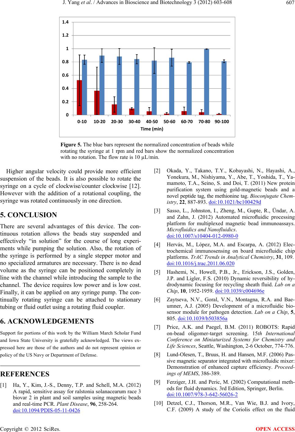
Figure 5. The blue bars represent the normalized concentration of beads while
rotating the syringe at 1 rpm and red bars show the normalized concentration
with no rotation. The flow rate is 10 µL/min.
Higher angular velocity could provide more efficient
suspension of the beads. It is also possible to rotate the
syringe on a cycle of clockwise/counter clockwise [12].
However with the addition of a rotational coupling, the
syringe was rotated continuously in one direction.
5. CONCLUSION
There are several advantages of this device. The con-
tinuous rotation allows the beads stay suspended and
effectively “in solution” for the course of long experi-
ments while pumping the solution. Also, the rotation of
the syringe is performed by a single stepper motor and
no specialized armatures are necessary. There is no dead
volume as the syringe can be positioned completely in
line with the channel while introducing the sample to the
channel. The device requires low power and is low cost.
Finally, it can be applied on any syringe pump. The con-
tinually rotating syringe can be attached to stationary
tubing or fluid outlet using a rotating fluid coupler.
6. ACKNOWLEDGEMENTS
Support for portions of this work by the William March Scholar Fund
and Iowa State University is gratefully acknowledged. The views ex-
pressed here are those of the authors and do not represent opinion or
policy of the US Navy or Department of Defense.
REFERENCES
[1] Ha, Y., Kim, J.-S., Denny, T.P. and Schell, M.A. (2012)
A rapid, sensitive assay for ralstonia solanacearum race 3
biovar 2 in plant and soil samples using magnetic beads
and real-time PCR. Plant Disease, 96, 258-264.
doi:10.1094/PDIS-05-11-0426
[2] Okada, Y., Takano, T.Y., Kobayashi, N., Hayashi, A.,
Yonekura, M., Nishiyama, Y., Abe, T., Yoshida, T., Ya-
mamoto, T.A., Seino, S. and Doi, T. (2011) New protein
purification system using gold-magnetic beads and a
novel peptide tag, the methionine tag. Bioconjugate Chem-
istry, 22, 887-893. doi:10.1021/bc100429d
[3] Sasso, L., Johnston, I., Zheng, M., Gupte, R., Ündar, A.
and Zahn, J. (2012) Automated microuidic processing
platform for multiplexed magnetic bead immunoassays.
Microfluidics and Nanofluidics.
doi:10.1007/s10404-012-0980-0
[4] Hervás, M., López, M.A. and Escarpa, A. (2012) Elec-
trochemical immunosensing on board microfluidic chip
platforms. TrAC Trends in Analytical Chemistry, 31, 109.
doi:10.1016/j.trac.2011.06.020
[5] Hashemi, N., Howell, P.B., Jr., Erickson, J.S., Golden,
J.P. and Ligler, F.S. (2010) Dynamic reversibility of hy-
drodynamic focusing for recycling sheath fluid. Lab on a
Chip, 10, 1952-1959. doi:10.1039/c004696e
[6] Zaytseva, N.V., Goral, V.N., Montagna, R.A. and Bae-
umner, A.J. (2005) Development of a microfluidic bio-
sensor module for pathogen detection. Lab on a Chip, 5,
805. doi:10.1039/b503856a
[7] Price, A.K. and Paegel, B.M. (2011) ROBOTS: Rapid
on-bead oligomer-target screening. 15th International
Conference on Miniaturized Systems for Chemistry and
Life Sciences, Seattle, Washington, 2-6 October, 774-776.
[8] Lund-Olesen, T., Bruus, H. and Hansen, M.F. (2006) Pas-
sive magnetic separator integrated with microfluidic mixer:
Demonstration of enhanced capture efficiency. Proceed-
ings of MEMS, 386-389.
[9] Ferziger, J.H. and Peric, M. (2002) Computational meth-
ods for fluid dynamics. 3rd Edition, Springer, Berlin.
doi:10.1007/978-3-642-56026-2
[10] Detzel, C.J., Thorson, M.R., Van Wie, B.J. and Ivory,
C.F. (2009) A study of the Coriolis effect on the fluid
Copyright © 2012 SciRes. OPEN ACCESS
J. Yang et al. / Advances in Bioscience and Biotechnology 3 (2012) 603-608
608
flow profile in a centrifugal bioreactor. Biotechnology
Progress, 25, 1025-1034. doi:10.1002/btpr.183
[11] Hammond, T.G. and Hammond, J.M. (2001) Optimized
suspension culture: The rotating-wall vessel. American
Journal of Physiology, 281, F12-F25.
[12] Zhou, S.W. (2004) Photocatalytic treatment of wastewa-
ter contaminated with organic waste and heavy metal
from semiconductor industry. National University of Sin-
gapore, Singapore City.
Copyright © 2012 SciRes. OPEN ACCESS