Paper Menu >>
Journal Menu >>
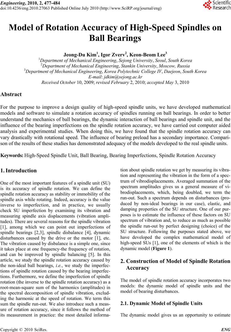 Engineering, 2010, 2, 477-484 doi:10.4236/eng.2010.27063 Published Online July 2010 (http://www.SciRP.org/journal/eng) Copyright © 2010 SciRes. ENG 477 Model of Rotation Accuracy of High-Speed Spindles on Ball Bearings Jeong-Du Kim1, Igor Zverv2, Keon-Beom Lee3 1Department of Mechanical Engineering, Sejong University, Seoul, South Korea 2Department of Mechanical Engineering, Stankin University, Moscow, Russia 3Department of Mechanical Engineering, Korea Polytechnic College IV, Daejeon, South Korea E-mail: jdkim@sejong.ac.kr Received October 10, 2009; revised February 2, 2010; acce pte d May 3, 2010 Abstract For the purpose to improve a design quality of high-speed spindle units, we have developed mathematical models and software to simulate a rotation accuracy of spindles running on ball bearings. In order to better understand the mechanics of ball bearings, the dynamic interaction of ball bearings and spindle unit, and the influence of the bearing imperfections on the spindle rotation accuracy, we have carried out computer aided analysis and experimental studies. When doing this, we have found that the spindle rotation accuracy can vary drastically with rotational speed. The influence of bearing preload has a secondary importance. Compari- son of the results of these studies has demonstrated adequacy of the models developed to the real spindle units. Keywords: High-Speed Spindle Unit, Ball Bearing, Bearing Imperfections, Spindle Rotation Accuracy 1. Introduction One of the most important features of a spindle unit (SU) is its accuracy of spindle rotation. We can define the spindle rotation accuracy as stability or immobility of the spindle axis while rotating. Indeed, accuracy is the value inverse to imperfection, and in practice, we usually check SU imperfection by examining its vibration and measuring spindle axis displacements (vibration ampli- tudes). There are several reasons for the spindle vibration [1], among which we can point out imperfections of spindle bearings [2,3], spindle disbalance [4], dynamic disturbances caused by the drive or the motor [1], etc. The vibration caused by disbalance is a simple one, since it takes place at one frequency-the frequency of rotation, and can be improved by spindle balancing [5]. In this article, we study the spindle rotation accuracy caused by the non-ideal ball bearings, i.e., we study the imperfec- tions of spindle rotation caused by the bearing imperfec- tions. Furthermore, we define the imperfection of spindle rotation (the inverse to the spindle rotation accuracy) as a root-mean-square sum of the harmonics (amplitudes) in the spectral decomposition of spindle vibration, exclud- ing the harmonic at the speed of rotation. We term this sum the spindle run-out. We also introduce such a meas- ure of rotation accuracy, since it follows the method of its measurement in practice: the most detailed informa- tion about spindle rotation we get by measuring its vibra- tion and representing the vibration in the form of a spec- trum of vibrodisplacements. Averaged summation of the spectrum amplitudes gives us a general measure of vi- brodisplacements, which, being doubled, we term the run-out. Such a spectrum depends on disturbances (pro- duced by non-ideal bearings in our case), elastic, and damping properties of the SU structure. One of our pur- poses is to estimate the influence of these factors on SU spectrum of vibration and, to reduce as much as possible the spindle run-out by perfect designing (choice) of the SU structure. Following the purposes stated above, we have developed the complex mathematical model of high-speed SUs [1], one of the elements of which is the dynamic model (Figure 1). 2. Construction of Model of Spindle Rotation Accuracy The model of spindle rotation accuracy incorporates two models: the dynamic model of spindle units and the model of bearing disturbances. 2.1. Dynamic Model of Spindle Units The dynamic model gives us an opportunity to estimate 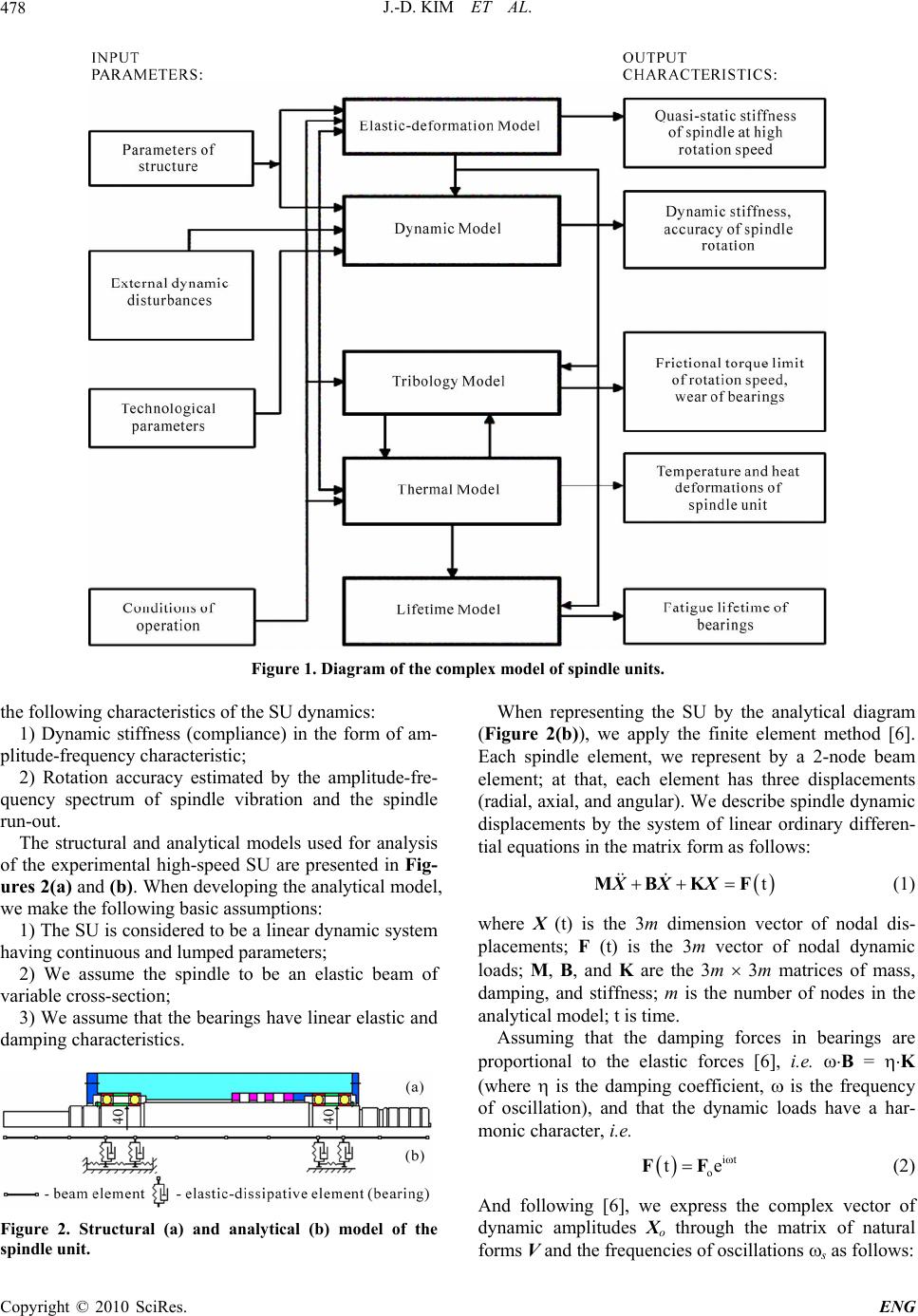 J.-D. KIM ET AL. 478 Figure 1. Diagram of the complex model of spindle units. the following characteristics of the SU dynamics: 1) Dynamic stiffness (compliance) in the form of am- plitude-frequency characteristic; 2) Rotation accuracy estimated by the amplitude-fre- quency spectrum of spindle vibration and the spindle run-out. The structural and analytical models used for analysis of the experimental high-speed SU are presented in Fig- ures 2(a) and (b). When developing the analytical model, we make the following basic assumptions: 1) The SU is considered to be a linear dynamic system having continuous and lumped parameters; 2) We assume the spindle to be an elastic beam of variable cross-section; 3) We assume that the bearings have linear elastic and damping characteristics. Figure 2. Structural (a) and analytical (b) model of the spindle unit. When representing the SU by the analytical diagram (Figure 2(b)), we apply the finite element method [6]. Each spindle element, we represent by a 2-node beam element; at that, each element has three displacements (radial, axial, and angular). We describe spindle dynamic displacements by the system of linear ordinary differen- tial equations in the matrix form as follows: t MBKF XXX (1) where X (t) is the 3m dimension vector of nodal dis- placements; F (t) is the 3m vector of nodal dynamic loads; M, B, and K are the 3m 3m matrices of mass, damping, and stiffness; m is the number of nodes in the analytical model; t is time. Assuming that the damping forces in bearings are proportional to the elastic forces [6], i.e. B = K (where is the damping coefficient, is the frequency of oscillation), and that the dynamic loads have a har- monic character, i.e. it o te FF (2) And following [6], we express the complex vector of dynamic amplitudes Xo through the matrix of natural forms V and the frequencies of oscillations s as follows: Copyright © 2010 SciRes. ENG  J.-D. KIM ET AL.479 T o 22 1 1s VV i diagFW FXo o 2 (3) where Fo is the complex vector of amplitude nodal loads; W is the matrix of frequency functions; s is the number of natural frequency; i is the imaginary unit. Thus, the modal matrix V has the properties of orthogonality [6], i.e. Tunit matrixVVME (4) T s VV Kdiag (5) Solution (3) we derived by expansion of vibration forced amplitudes into the series in terms of the eigen- functions. At that, the amplitude-frequency characteris- tics represented by formula (3) correspond to the mono- harmonic vibrodisturbance F(t) by formula (2). In the case of polyharmonic vibrodisturbance produced by sev- eral bearings, we can derive the dynamic load as follows: it+ 1 t Nkk kk pk e FF (6) where p is the number of bearings in SU; N is the num- ber of spectral harmonics to be considered; Fk (k) is the vector of nodal loads of the k-th harmonic; k and k are the frequency and phase of the k-th harmonic. The hardware we apply for measurements of spindle vibration spectrum gives us an opportunity to make a root-mean-square summation for all the amplitude har- monics, which get into the frequency band r (r = 1, 2, 3, ..., q) to be checked, where q is the number of fre- quency bands. The root-mean-square amplitude of vi- brodisplacements of the vector Xo on the coordinate j in the frequency band r (the double of which we term the run-out) can be determined as follows: 2 2 A kr jr jnnk p WF (7) where Wjn are the elements of the matrix of frequency function (3); Fn (k) is the k-th harmonic of the n-th component of the vector of vibrodisturbances; kr denotes summation of all the harmonics k, which enter into the frequency band r. Formula (7) is used to es- timate the spindle rotation accuracy in the frequency band r to be checked. 2.2. Model of Ball Bearing Disturbances High-speed ball bearings have several sources of distur- bances [7], i.e. the disturbing forces, which produce SU vibration. These include the following: 1) Imperfections of macro geometry of the bearing races, such as out-of-roundness, waviness, radial and axial run-outs, possible dents and scratches, etc; 2) Imperfections of macro geometry of the balls, which are similar to those of the races, plus possible dif- ference of ball sizes; 3) Imperfections of micro geometry of the races and balls i.e. surface roughness (some of these imperfections protrude through the oil film generated between races and balls while normal operation and produce collisions); 4) Variation of bearing stiffness while rotation (the ra- dial stiffness depends on position of the balls with re- spect to the radial force vector); 5) Heterogeneity of elastic properties of the races and balls; 6) Lubricant contamination; 7) Motion of cage; 8) Disbalance of spindle and bearing misalignments, etc. However, when analyzing precision bearings operat- ing in favourable conditions, we can neglect some of these sources and save only the two first ones. Balmont and Zverev consider the theory of bearing having these inperfections in [2]. Some of the results obtained are presented in Table 1, where the spectrum of radial vi- brodisturbances generated by imperfect ball bearing is presented. Where, z is the number of balls in bearing, is the contact angle, is the axial clearance-tightness of bearing m , R K is the radial stiffness of bearing 1 Nm ; ,, oi b are the relative rotational speeds of a bearing’s cage to outer and inner rings, and balls around their own axis H z; is the number of harmonics of Fourier-series expansion of ball radius, is the amplitude of the harmonic of ball radius; ,, , are the numbers and amplitudes of har- monics of imperfections of outer and inner races; is the allowance of out of diameter of balls m ; 0,1,k , 2,... m1,2,... are the coefficients. Table 1 interrelates two types of the spectra: the spec- trum of imperfections of ball bearing races and balls (the input parameters) represented by amplitudes of these imperfections a (), a (), and a (), and the spectrum of radial vibrodisturbances (disturbing forces) determined by the frequencies and amplitudes of harmonics (the output parameters), which are represented in the two right columns of Table 1. The spectrum of angular vi- brodisturbances coincides with the spectrum of the radial ones and differs in amplitudes by the multiplier 0.5Dmtg (), where Dm is the diameter of the circle, which goes through the centres of bearing balls. Spectrum of axial vibrodisturbances of ball bearing having imperfections of macro geometry is also considered in [2]. Copyright © 2010 SciRes. ENG  J.-D. KIM ET AL. Copyright © 2010 SciRes. ENG 480 Table 1. Spectrum of radial vibrodisturbances of ball bearing. Bearing elements Harmonic number Frequency [Hz] Amplitude [N] Outer raceway 1mz o 1 R Ka Inner raceway 1kz io R Ka Outer and inner raceway 1 1 mz mz oi oi o o R ctg Ka 4 a Balls (out-of-roundness) ,,, b o R 2 Ka cosz Balls (out-of-diameter) 0 o R K3cosz Outer race and balls (out-of-diameter) 0; m o 1 R ctg Ka 3z Inner race and balls (out-of-diameter) 0; k io R ctg Ka 3z The amplitudes of imperfections a (), a (), and a () have a particular physical sense. The subscripts and ar- guments , , and notify numbers of harmonics of ex- pansions of imperfections into Fourier series and attrib- ute them to outer race (), inner race (), and balls (). At that, the two first ones are the combinations of imper- fections of races measured in three directions: transversal, radial, and axial, which can be designated by upper in- dexes (1), (2), and (3), respectively (Figure 3). = 0 = 1 = 2 = 1 = 2 = 1 = 2 = 3 Thus, for example, a ()(1) is the amplitude of the harmonic of bearing outer race cross-section imperfec- tion; a ()(2) is the amplitude of the harmonic of bear- ing outer race radial imperfection; a ()(3) is the ampli- tude of the harmonic of bearing outer race axial im- perfection. These imperfections can be measured using the round-meter gauges of the Taylor & Hobson Co. At that, the measurements of the axial and radial imperfec- tion spectra should be made by the Talyrond instrument and the measurements of the cross-section imperfections- by the Talyserf instrument (both of them should be equipped by the Talydate facility for expansion of the traces made into Fourier series). Summation of the com- ponents should be made as follows: Figure 3. Macro geometric imperfections of bearing race- ways. λλλ 23 1 222 cos 1 cos tgaaa a = 3, and a = 3 to triangularity, etc; a = 1 and a = 1 has no meaning; a = 1 corresponds to eccentricity of the inner race with respect to rotational axis, i.e. to spindle disbal- ance (which is an imperfection of the SU accuracy, not of the bearing); a = 0 corresponds to averaged difference between diameters of balls. a (8) 23 1 22 cos 1 cos tgaaa 2 a (9) The principle difficulty when simulating the ball bearing vibration spectrum makes inputting of the spec- tra of bearing imperfections. It looks to be impossible to measure and to input all the harmonics of races and balls individually. In order to avoid it, we can use some ex- trapolation based on the results of measurements of races and balls, and represent the spectra of imperfections by the following hyperbolic functions [2]: Representation of imperfections of races and balls by Fourier series has a clear mechanical sense: harmonics 3 12 ,,aaa a = 2, a = 2, and a = 2 correspond to ovality of outer race, inner race, and balls (when averaged), respectively; a = 3, (10) 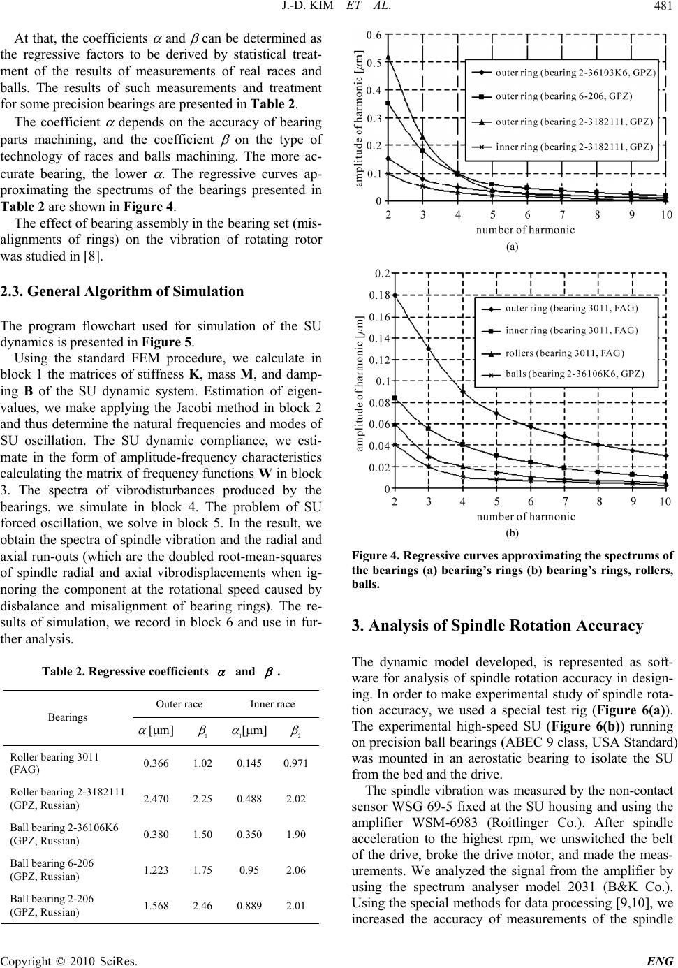 J.-D. KIM ET AL.481 At that, the coefficients and can be determined as the regressive factors to be derived by statistical treat- ment of the results of measurements of real races and balls. The results of such measurements and treatment for some precision bearings are presented in Table 2. The coefficient depends on the accuracy of bearing parts machining, and the coefficient on the type of technology of races and balls machining. The more ac- curate bearing, the lower . The regressive curves ap- proximating the spectrums of the bearings presented in Table 2 are shown in Figure 4. The effect of bearing assembly in the bearing set (mis- alignments of rings) on the vibration of rotating rotor was studied in [8]. 2.3. General Algorithm of Simulation The program flowchart used for simulation of the SU dynamics is presented in Figure 5. Using the standard FEM procedure, we calculate in block 1 the matrices of stiffness K, mass M, and damp- ing B of the SU dynamic system. Estimation of eigen- values, we make applying the Jacobi method in block 2 and thus determine the natural frequencies and modes of SU oscillation. The SU dynamic compliance, we esti- mate in the form of amplitude-frequency characteristics calculating the matrix of frequency functions W in block 3. The spectra of vibrodisturbances produced by the bearings, we simulate in block 4. The problem of SU forced oscillation, we solve in block 5. In the result, we obtain the spectra of spindle vibration and the radial and axial run-outs (which are the doubled root-mean-squares of spindle radial and axial vibrodisplacements when ig- noring the component at the rotational speed caused by disbalance and misalignment of bearing rings). The re- sults of simulation, we record in block 6 and use in fur- ther analysis. Table 2. Regressive coefficients and . Outer race Inner race Bearings [m] [m] Roller bearing 3011 (FAG) 0.366 1.02 0.145 0.971 Roller bearing 2-3182111 (GPZ, Russian) 2.470 2.25 0.488 2.02 Ball bearing 2-36106K6 (GPZ, Russian) 0.380 1.50 0.350 1.90 Ball bearing 6-206 (GPZ, Russian) 1.2231.75 0.95 2.06 Ball bearing 2-206 (GPZ, Russian) 1.568 2.46 0.889 2.01 (a) (b) Figure 4. Regressive curves approximating the spectrums of the bearings (a) bearing’s rings (b) bearing’s rings, rollers, balls. 3. Analysis of Spindle Rotation Accuracy The dynamic model developed, is represented as soft- ware for analysis of spindle rotation accuracy in design- ing. In order to make experimental study of spindle rota- tion accuracy, we used a special test rig (Figure 6(a)). The experimental high-speed SU (Figure 6(b)) running on precision ball bearings (ABEC 9 class, USA Standard) was mounted in an aerostatic bearing to isolate the SU from the bed and the drive. The spindle vibration was measured by the non-contact sensor WSG 69-5 fixed at the SU housing and using the amplifier WSM-6983 (Roitlinger Co.). After spindle acceleration to the highest rpm, we unswitched the belt of the drive, broke the drive motor, and made the meas- urements. We analyzed the signal from the amplifier by using the spectrum analyser model 2031 (B&K Co.). Using the special methods for data processing [9,10], we increased the accuracy of measurements of the spindle Copyright © 2010 SciRes. ENG 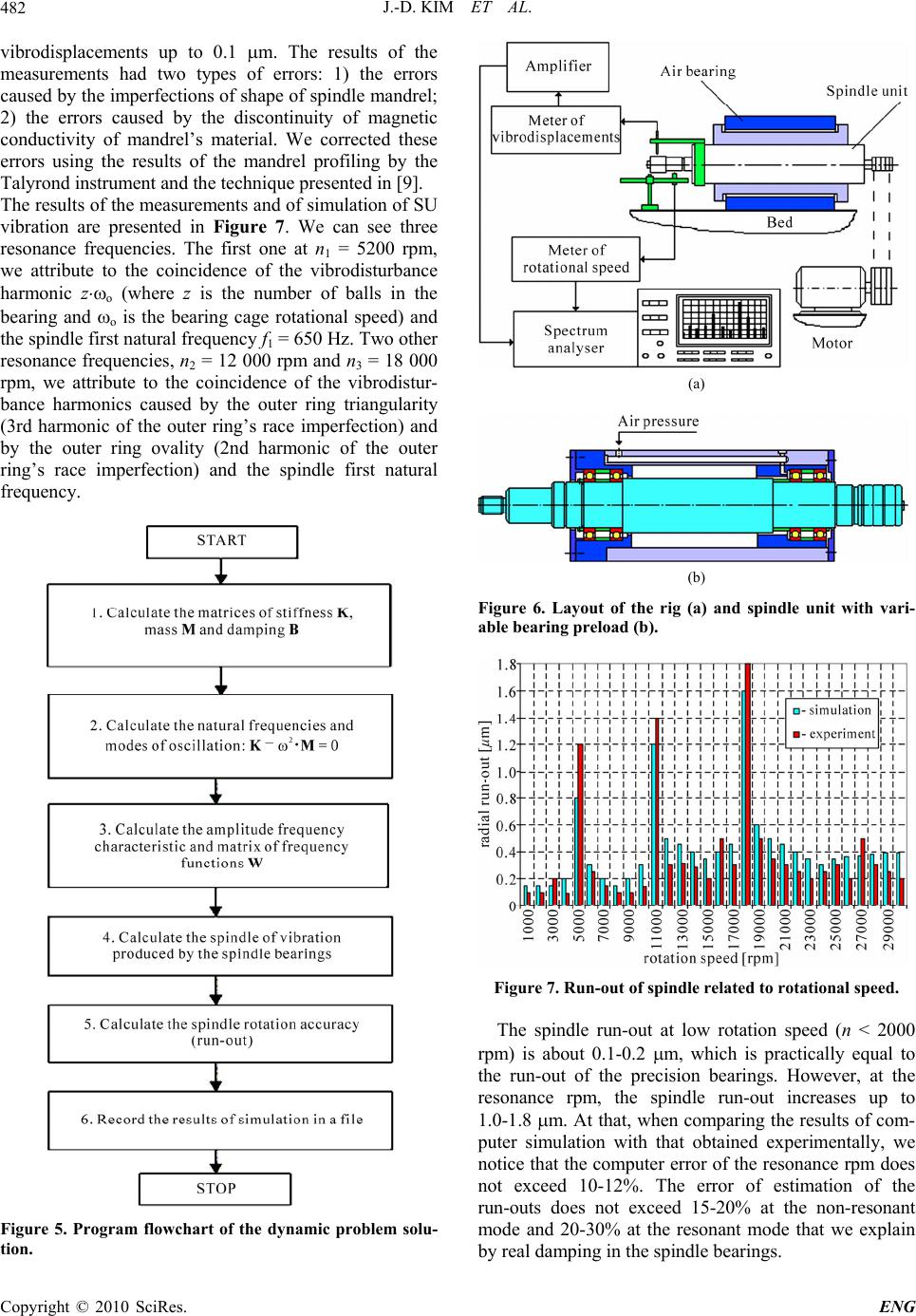 J.-D. KIM ET AL. 482 vibrodisplacements up to 0.1 m. The results of the measurements had two types of errors: 1) the errors caused by the imperfections of shape of spindle mandrel; 2) the errors caused by the discontinuity of magnetic conductivity of mandrel’s material. We corrected these errors using the results of the mandrel profiling by the Talyrond instrument and the technique presented in [9]. The results of the measurements and of simulation of SU vibration are presented in Figure 7. We can see three resonance frequencies. The first one at n1 = 5200 rpm, we attribute to the coincidence of the vibrodisturbance harmonic zo (where z is the number of balls in the bearing and o is the bearing cage rotational speed) and the spindle first natural frequency f1 = 650 Hz. Two other resonance frequencies, n2 = 12 000 rpm and n3 = 18 000 rpm, we attribute to the coincidence of the vibrodistur- bance harmonics caused by the outer ring triangularity (3rd harmonic of the outer ring’s race imperfection) and by the outer ring ovality (2nd harmonic of the outer ring’s race imperfection) and the spindle first natural frequency. Figure 5. Program flowchart of the dynamic problem solu- tion. (a) (b) Figure 6. Layout of the rig (a) and spindle unit with vari- able bearing preload (b). Figure 7. Run-out of spindle related to rotational speed. The spindle run-out at low rotation speed (n < 2000 rpm) is about 0.1-0.2 m, which is practically equal to the run-out of the precision bearings. However, at the resonance rpm, the spindle run-out increases up to 1.0-1.8 m. At that, when comparing the results of com- puter simulation with that obtained experimentally, we notice that the computer error of the resonance rpm does not exceed 10-12%. The error of estimation of the run-outs does not exceed 15-20% at the non-resonant mode and 20-30% at the resonant mode that we explain by real damping in the spindle bearings. Copyright © 2010 SciRes. ENG 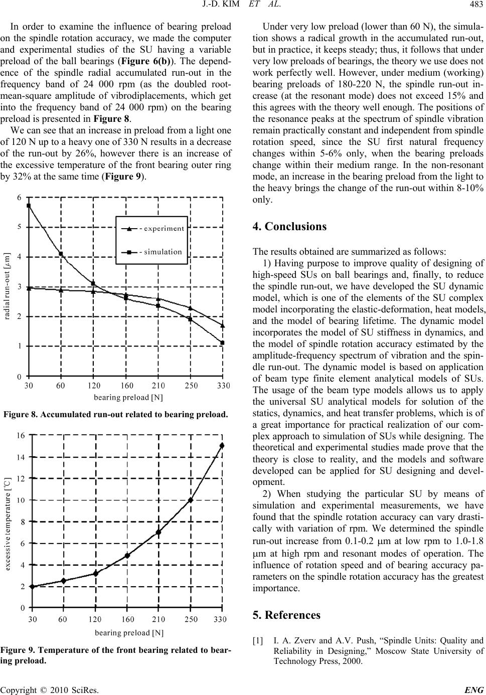 J.-D. KIM ET AL.483 In order to examine the influence of bearing preload on the spindle rotation accuracy, we made the computer and experimental studies of the SU having a variable preload of the ball bearings (Figure 6(b)). The depend- ence of the spindle radial accumulated run-out in the frequency band of 24 000 rpm (as the doubled root- mean-square amplitude of vibrodiplacements, which get into the frequency band of 24 000 rpm) on the bearing preload is presented in Figure 8. We can see that an increase in preload from a light one of 120 N up to a heavy one of 330 N results in a decrease of the run-out by 26%, however there is an increase of the excessive temperature of the front bearing outer ring by 32% at the same time (Figure 9). Figure 8. Accumulated run-out related to be ar ing pr eload. Figure 9. Temperature of the front bearing related to bear- ing preload. Under very low preload (lower than 60 N), the simula- tion shows a radical growth in the accumulated run-out, but in practice, it keeps steady; thus, it follows that under very low preloads of bearings, the theory we use does not work perfectly well. However, under medium (working) bearing preloads of 180-220 N, the spindle run-out in- crease (at the resonant mode) does not exceed 15% and this agrees with the theory well enough. The positions of the resonance peaks at the spectrum of spindle vibration remain practically constant and independent from spindle rotation speed, since the SU first natural frequency changes within 5-6% only, when the bearing preloads change within their medium range. In the non-resonant mode, an increase in the bearing preload from the light to the heavy brings the change of the run-out within 8-10% only. 4. Conclusions The results obtained are summarized as follows: 1) Having purpose to improve quality of designing of high-speed SUs on ball bearings and, finally, to reduce the spindle run-out, we have developed the SU dynamic model, which is one of the elements of the SU complex model incorporating the elastic-deformation, heat models, and the model of bearing lifetime. The dynamic model incorporates the model of SU stiffness in dynamics, and the model of spindle rotation accuracy estimated by the amplitude-frequency spectrum of vibration and the spin- dle run-out. The dynamic model is based on application of beam type finite element analytical models of SUs. The usage of the beam type models allows us to apply the universal SU analytical models for solution of the statics, dynamics, and heat transfer problems, which is of a great importance for practical realization of our com- plex approach to simulation of SUs while designing. The theoretical and experimental studies made prove that the theory is close to reality, and the models and software developed can be applied for SU designing and devel- opment. 2) When studying the particular SU by means of simulation and experimental measurements, we have found that the spindle rotation accuracy can vary drasti- cally with variation of rpm. We determined the spindle run-out increase from 0.1-0.2 m at low rpm to 1.0-1.8 m at high rpm and resonant modes of operation. The influence of rotation speed and of bearing accuracy pa- rameters on the spindle rotation accuracy has the greatest importance. 5. References [1] I. A. Zverv and A.V. Push, “Spindle Units: Quality and Reliability in Designing,” Moscow State University of Technology Press, 2000. Copyright © 2010 SciRes. ENG 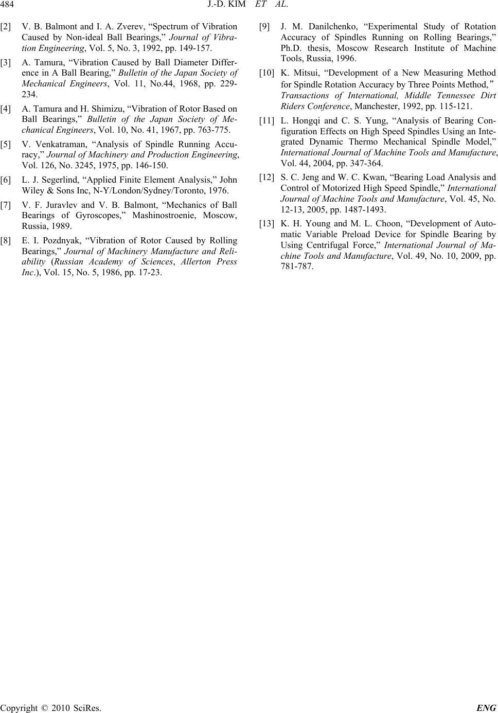 J.-D. KIM ET AL. Copyright © 2010 SciRes. ENG 484 [2] V. B. Balmont and I. A. Zverev, “Spectrum of Vibration Caused by Non-ideal Ball Bearings,” Journal of Vibra- tion Engineering, Vol. 5, No. 3, 1992, pp. 149-157. [3] A. Tamura, “Vibration Caused by Ball Diameter Differ- ence in A Ball Bearing,” Bulletin of the Japan Society of Mechanical Engineers, Vol. 11, No.44, 1968, pp. 229- 234. [4] A. Tamura and H. Shimizu, “Vibration of Rotor Based on Ball Bearings,” Bulletin of the Japan Society of Me- chanical Engineers, Vol. 10, No. 41, 1967, pp. 763-775. [5] V. Venkatraman, “Analysis of Spindle Running Accu- racy,” Journal of Machinery and Production Engineering, Vol. 126, No. 3245, 1975, pp. 146-150. [6] L. J. Segerlind, “Applied Finite Element Analysis,” John Wiley & Sons Inc, N-Y/London/Sydney/Toronto, 1976. [7] V. F. Juravlev and V. B. Balmont, “Mechanics of Ball Bearings of Gyroscopes,” Mashinostroenie, Moscow, Russia, 1989. [8] E. I. Pozdnyak, “Vibration of Rotor Caused by Rolling Bearings,” Journal of Machinery Manufacture and Reli- ability (Russian Academy of Sciences, Allerton Press Inc.), Vol. 15, No. 5, 1986, pp. 17-23. [9] J. M. Danilchenko, “Experimental Study of Rotation Accuracy of Spindles Running on Rolling Bearings,” Ph.D. thesis, Moscow Research Institute of Machine Tools, Russia, 1996. [10] K. Mitsui, “Development of a New Measuring Method for Spindle Rotation Accuracy by Three Points Method,” Transactions of International, Middle Tennessee Dirt Riders Conference, Manchester, 1992, pp. 115-121. [11] L. Hongqi and C. S. Yung, “Analysis of Bearing Con- figuration Effects on High Speed Spindles Using an Inte- grated Dynamic Thermo Mechanical Spindle Model,” International Journal of Machine Tools and Manufacture, Vol. 44, 2004, pp. 347-364. [12] S. C. Jeng and W. C. Kwan, “Bearing Load Analysis and Control of Motorized High Speed Spindle,” International Journal of Machine Tools and Manufacture, Vol. 45, No. 12-13, 2005, pp. 1487-1493. [13] K. H. Young and M. L. Choon, “Development of Auto- matic Variable Preload Device for Spindle Bearing by Using Centrifugal Force,” International Journal of Ma- chine Tools and Manufacture, Vol. 49, No. 10, 2009, pp. 781-787. |