Smart Grid and Renewable Energy, 2012, 3, 194-203
http://dx.doi.org/10.4236/sgre.2012.33027 Published Online August 2012 (http://www.SciRP.org/journal/sgre)
Simulation of Dynamic Response of Small
Wind-Photovoltaic-Fuel Cell Hybrid Energy System
Saeid Esmaeili1,2, Mehdi Shafiee1,3
1Energy Department, International Center for Science, High Technology & Environmental Sciences, Kerman, Iran; 2Electrical De-
partment, Shahid Bahonar University of Kerman, Kerman, Iran; 3Electrical Department, Ferdowsi University of Mashhad, Mashhad,
Iran.
Email: sesm76@yahoo.com, shafiemehdi@yahoo.com
Received October 26th, 2011; revised May 16th, 2012; accepted May 23rd, 2012
ABSTRACT
Renewable energy systems are of importance as being modular, nature-friendly and domestic. Among renewable energy
systems, a great deal of research has been conducted especially on photovoltaic effect, wind energy and fuel cell in the
recent years. This paper describes dynamic modeling and simulation results of a small wind-photovoltaic-fuel cell
hybrid energy system. The hybrid system consists of a 500 W wind turbine, a photovoltaic, a proton exchange
membrane fuel cell (PEMFC), ultracapacitors, an electrolyzer, a boost converter, controllers and a power converter that
simulated using MATLAB solver. This kind of hybrid system is completely stand-alone, reliable and has high
efficiency. In order to minimize sudden variations in voltage magnitude ultracapacitors are proposed. Power converter
and inverter are used to produce ac output power. Dynamics of fuel-cell component such as double layer capacitance
are also taken into account. Control scheme of fuel-cell flow controller and voltage regulators are based on PID
controllers. Dynamic responses of the system for a step change in the electrical load and wind speed are presented.
Results showed that the ability of the system in adapting itself to sudden changes and new conditions. Combination of
PV and wind renewable sources is made the advantage of using this system in regions which have higher wind speeds
in the seasons that suffers from less sunny days and vice versa.
Keywords: Wind Energy; Photovoltaic; Fuel-Cell; Hybrid Energy Systems; Dynamics of Energy System
1. Introduction
The rapid depletion of fossil fuel resources on a world-
wide basis has necessitated an urgent search for alterna-
tive energy sources to meet to the present day demands.
Alternative energy resources, such as solar and wind en-
ergies, are clean, inexhaustible and environment friendly
potential resources of renewable energy options. It is
prudent that neither a standalone solar nor a wind energy
system can provide a continuous supply of energy due to
seasonal and periodical variations [1-3]. To solve these
drawbacks conventional battery storage has been used.
But batteries can store a limited amount of power for a
short period of time. For long-term storage electrical
power produced by wind turbines or PV arrays can be
converted into hydrogen using an electrolyzer for later
use in fuel cell. So these conventional batteries can be
replaced with fuel cells as non-polluting and high effi-
ciency storage devices. Advantages in wind and PV en-
ergy technologies are the main reason of using hybrid
Wind/PV configurations, and fuel-cells can be work in
parallel with Wind/PV system as the device which can
save and generate electrical energy where it is necessary.
In addition the excess heat from a fuel-cell can also be
used for space heating or for the residential hot water.
This kind of energy storage in hydrogen form that uses
energy from wind turbine or PV to produce hydrogen for
later use is being studied at the hydrogen research insti-
tute [4,5]. The idea of an ultra-high-efficiency (UHE)
hybrid energy system consisting of wind turbine, a
photovoltaic and fuel cell exists in [6,7]. In [8] a man-
agement system is designed for a Wind-PV-Fuel cell
hybrid energy system to manage the power flow between
the system components in order to satisfy the load re-
quirements. In [9] a simple and economic control with
DC-DC converter is used for maximum power point
tracking and hence maximum power extraction from the
wind turbine and photovoltaic arrays. In order to insure
continuous power flow a fuel cell was also proposed in
this paper. An economic evaluation of a hybrid Wind-
PV-Fuel cell generation system for a house usage is pre-
sented in [10]. It is necessary to analyze this system in all
aspects such as: cost, efficiency, reliability, dynamic re-
sponse to load demand and power sources sudden
Copyright © 2012 SciRes. SGRE
Simulation of Dynamic Response of Small Wind-Photovoltaic-Fuel Cell Hybrid Energy System 195
changes and its control system. Since, these kinds of hy-
brid systems are operated under variable conditions such
as sudden variations in load demand or wind speed.
Therefore in this paper the dynamic response of a Wind-
PV-Fuel cell hybrid energy system is analyzed under
some critical operating conditions. It is assumed that the
output power of PV plus wind turbine can supply the
nominal load demand, in the case of low wind or lack of
ambient irradiation a share of power can be supplied
from the fuel cell. If PV and wind turbine output power
exceeds the demand, the excess power is used to produce
hydrogen for later use in the fuel cell. The system de-
scription, modeling and a study of system dynamics are
presented below.
2. System Description
The proposed system consists of a PV array [11], a
southwest wind power AIR 404 wind turbine, a proton
exchange membrane fuel cell (PEMFC), an ultracapaci-
tor bank, an electrolyzer, power converter and inverter, a
wind mast, a dump load, and controllers like in [6].
Schematic diagram of the system is depicted in Figure 1.
Wind turbine with an AC/DC converter, PV array and
fuel cell with DC/DC converters will connect together to
a dc bus and after that an inverter will convert this DC
power to AC one to supply the load. The load electricity
demand is supplied from wind turbine output power plus
PV array output in normal operation condition of the
system. Each of these two power sources has its own
controller. A storage tank with an initial amount of hy-
drogen is also taken into account to see fuel storage
variations. The fuel cell stack is consists of 65 individual
fuel cells connected in series. Fuel cell controllers are
designed to control O2 and H2 flows in order to produce
more power. These controllers will let more fuel flow as
fuel cell voltage drops under 60 volts. This action will
prevent voltage variations caused by load current changes.
The ultra capacitor bank is in parallel with fuel cell out-
put to reduce sudden voltage variation changes. This
system is also consists a power conditioner block which
is composed of a boost converter that regulates the DC
bus voltage in 200 volts and an inverter that converts this
DC power into usable AC power for the system load. The
system is modeled by standard classical method [12,13].
A set of differential equations and PID controllers by a
transfer function is used for modeling.
2.1. Overall Power Management Strategy
Figure 2 shows the block diagram of the overall control
strategy for the proposed hybrid energy system. Strategy
of system operation is according to the following rules:
1) If load demand () exceeds the available power
generated by wind (P) and solar sources () the fuel
cell () will come into action. Therefore, the power
balance equation can be written as:
Load
P
wind PV
P
FC
P
LoadwindPVFC sys
PPPP,P0
 (1)
2) If the wind and solar generations exceeds the load
demand, then the surplus power is diverted toward the
electrolyzer. Therefore, the power balance equation can
be written as:
elecwindPVLoad sys
PP PP,P0
  (2)
3) If the wind and solar generations equal the load
demand, then whole power generated by renewable
sources is injected to the load. Therefore, the power bal-
ance equation can be written as:
LoadwindPV sys
PPP,P0
 (3)
3. Wind-PV-Fuel Cell System Modeling
As it can be seen in Figure 1, the system consists of bine,
PV arrays, fuel cell stack, hydrogen storage tank, elec-
Figure 1. Configuration of hybrid energy system.
Copyright © 2012 SciRes. SGRE
Simulation of Dynamic Response of Small Wind-Photovoltaic-Fuel Cell Hybrid Energy System
196
Figure 2. Block diagram of the overall control scheme for the proposed hybrid energy system.
trolyzer, ultracapacitors, power converter and controllers.
Dynamic component models, used in this study, are sum-
marized in the following sections [12,13].
3.1. Photovoltaic Model
PV effect is a basic physical process through which solar
energy is converted directly into electrical energy. The
PV cell, or a solar cell, is presented by an electrical
equivalent one-diode model [11,14] as shown in Figure
3. The model contains a current source IL, one diode and
a series resistance Rs (in ohms), which represents the re-
sistance inside each cell and in the connection between
the cells. Relationship between the output voltage V (in
volts), and the load current I (in amperes) of a PV cell or
a module can be expressed as [11]

s
LD L0
c
eVIR
II II Iexp1
mkT


 




(4)
where I0 is the saturation current, m is idealizing factor, k
is Boltzmann’s gas constant, Tc is the absolute tempera-
ture of the cell and e is electronic charge [11]. The I - V
characteristic curves of the PV model for a certain ambient
irradiation and cell temperature are given in Figure 4.
Effect of cell temperature variation in open circuit volt-
age is also considered in this model. In Figure 4, I
sc is
the short circuit current, Voc is the open circuit voltage, A
(Vmax I
max) is the maximum power point on the curve
where the load resistance is Ropt, MN and PS are constant
current and constant voltage criteria respectively. The
manufacturers supply PV cells in modules consisting of
NPM parallel branches and NSM solar cells in series. We
take NPM and NSM equal to 10,000 and 2000 respec-
tively.
Figure 3. Model for a single solar cell.
Figure 4. Current-voltage curve for a PV cell.
Copyright © 2012 SciRes. SGRE
Simulation of Dynamic Response of Small Wind-Photovoltaic-Fuel Cell Hybrid Energy System 197
3.2. Wind Turbine Model
This variable speed wind turbine is self-regulating with a
permanent magnet alternator. Self regulation is achieved
by twisting of blades (stall control). If the wind speed
increases to more than a specific number the wind tur-
bine quickly enters stall mode. It can avoid over speeds
by twisting its blades. This small wind turbine has the
ability of adapting itself to the wind speeds up to 17.9
m/s to achieve maximum available power. Turbine rotor
diameter is 1.14 m. The wind turbine power curve is as
the way illustrated in Figure 5 [12,15]. The dynamic of
wind turbine due to its rotor inertia (J), and controller
action is as Equation (5) when a friction based dynamic
model for the wind turbine rotor and a first order model
for the permanent magnet generator are used [12].


2
s0.25
ss0.7s0.25
y
x (5)
where x(t) is the power from the curve shown in Figure 5
and y(t) is the actual wind turbine output power.
3.3. Fuel Cell Model
Fuel cells are electrochemical devices that convert the
chemical energy of a reaction directly into electrical en-
ergy. Exchange membrane fuel-cell (PEMFC) has reli-
able performance under intermittent supply and is com-
mercially available at large industrial scale capacities.
This kind of fuel cell is suitable for large-scale stationary
generation and has fast dynamic response with a power
release response time of only 1 - 3 s [16]. In this paper a
group of PEMFC stacks were applied to enhance the
performance of the hybrid system. Parametric model of
PEMFC developed by Amphlett [17,18] using mechanistic
approach and a number of group parameters is used. The
number of stacks is 65. The H2 and O2 pressure, current
drawn and temperature variations can affect the fuel cell
output voltage. These voltage variations can be compensated
by fuel pressure controlling. Figure 5 is shown the elec-
trical equivalent of fuel cell. E is thermodynamic poten-
tial, Ra is the activation resistance and Rint is the fuel cell
internal resistant. The dynamics of the fuel cell voltage
can be modeled by the addition of a capacitor C to the
steady state model [19]. The effect of double charge
layer is also modeled by a capacitor C connected in par-
allel with the activation resistance as shown in Figure 6.
Fuel cell has two PID controller loops; one for O2 and
the other for H2 pressure. The controller gains are pre-
sented in Table 1. The controllers will become activated
when the output voltage of Fuel cell drops below 60 V.
3.4. Electrolyzer Model
The Electrolyzer works through simple water electrolysis:
a direct current is passed between two electrodes sub-
merged in water, which thereby decomposes into hydrogen
and oxygen. The hydrogen can then be collected from the
anode. The production rate of hydrogen in an electrolyzer
cell according to Faraday law can be achieved through
Equation (6).
2
Fce
H
ni
nm
2
ols
(6)
where ie is the electrolyzer current, nc is the number of
electrolyzer cells in series and F
is the Faraday effi-
ciency. For an electrolyzer working in 40˚C; Faraday
efficiency can be calculated as:

2
Fe
96.5exp0.09 i75.5 i

e
(7)
Figure 5. Power curve of wind turbine.
Figure 6. Equivalent circuit of PEMFC.
Table 1. PID Controllers parameters.
Kp Ti Td
Fuel-cell O2 flow controller3.14 0.5 0
Fuel-cell H2 flow controller5 0.5 0
Boost converter 5 0.5 0
Inverter 0.03 0.15 0
Copyright © 2012 SciRes. SGRE
Simulation of Dynamic Response of Small Wind-Photovoltaic-Fuel Cell Hybrid Energy System
Copyright © 2012 SciRes. SGRE
198
tude and frequency. The first stage consists of a boost
converter, which can regulate the output voltage into a
high voltage constant DC that is appropriate for the load
usage. Here, the boost converter is controlled with a PID
controller to regulate the high voltage bus at 200 V. This
could be achieved by adjusting the duty ratio, D, as gen-
erally given by the Equation (9).
In this paper we assume that the electrolyzer tempera-
ture to be constant. Dynamic modeling of electrolyzer and
fuel cells auxiliary equipment such as hydrogen storage
vessel, compressor, piping, valves, etc., are neglected.
3.5. Ultracapacitor Model
Ultracapacitors are energy storage devices with a con-
struction similar to batteries [13]. It can store energy and
release it when it is necessary. This can help the system
in short duration of the peak power. Such a device can be
use in parallel with fuel cell to reduce its voltage varia-
tions due to power variations. Ultracapacitors are with
low voltage rates. We have used four modules of Max-
well 435 F, 14 V ultracapacitor like in [13] to achieve the
desired operating voltage. The ultracapacitor can be
modeled using a capacitor in series with a resistor. Four
ultracapacitors modules in series have a total capacitance
(C) of 108.75 µF. each module has a series resistance (Rc)
of 4 m. Ultracapacitor is modeled as a low pass filter
with the transfer function in Equation (8).
boost
ucap
V1
V1
D
(9)
To supply the load the ac power can be achieved
through an inverter connected to the output of the boost-
ing converter. A pulse width modulation (PWM) single-
phase voltage source converter is used to control the
output voltage of the system. A PID controller is used to
control the voltage on 120 V and 60 HZ. The triangular
carrier wave frequency is considered to be 8 kHz [13].
3.7. Controllers
All subsystems controllers are chosen PID type in this
system, which have transfer function like in Equation
(10). Appropriate controller parameters are available in
Table 1.

ucap c
Fcells cc
Vs1RC
Vs1RR1R
C
(8)

2
pd
KsTs 1T
Ts s

(10)
where Rs is the stray capacitance and is equal to 0.01 .
3.6. Power Conditioner 4. Simulation and Discussion
The system is considered for stand-alone mode of opera-
tion and a two-stage power converter module is consid-
ered to regulate the output voltage at a standard magni
The simulated system in Matlab SIMULINK [20] is pre-
sented in Figure 7 [20]. It consists of seven main
Figure 7. Simulated system in Matlab SIMULINK.
Simulation of Dynamic Response of Small Wind-Photovoltaic-Fuel Cell Hybrid Energy System 199
subsystems that have been described in previous sections.
Wind turbine input and load resistance are two variable
inputs of the system. A fixed inductive load (100 mH) is
also added to variable resistive load. Step changes in load
resistance and wind speed are applied to analyze the dy-
namic response of the system. Load resistance changes at
t = 10 s from 35 to 10 and t = 20 s from 10 to 25
as seen in Figure 8. Wind speed changes at t = 20 s
from 9 to 12 m/s and returns to 9 m/s at t = 30 s as it is
clear from Figure 9. Simulation is run for 40 seconds.
Results are presented in Figures 10-18. Effects of input
step changes are obvious in the results. Figure 10 shows
the demand power, wind turbine, photovoltaic and fuel
cell output powers. As it is clear the demand power in-
creases at t = 10 s and decreases in t = 20 s by changes in
load resistance.
Figure 8. Load resistance.
Figure 9. Wind turbine input.
Figure 10. Load, fuel cell, PV and wind powers.
Copyright © 2012 SciRes. SGRE
Simulation of Dynamic Response of Small Wind-Photovoltaic-Fuel Cell Hybrid Energy System
200
The lack of power in t = 10 s is compensated by an in-
crease in O2 and H2 pressure and as a result a step change
in output power of fuel cell. Gas pressure variations in
fuel cell are presented in Figure 11. Resistance change
effects on output power of photovoltaic are also obvious
in Figure 10. Both PV and fuel cell output powers are
decreases when load resistance is increased at t = 20 s.
Output power of wind generator at t = 20 s is increased
after variations in wind speed. As it is obvious generated
power by PV and wind turbine is excess the load demand
at t = 22 s. The excess generated power is converted into
hydrogen to save in a tank for later use. The hydrogen-
generated (mol/s) in electrolyzer is presented in Figure
12. Although there is step variations in load and wind
turbine output power but as it is clear in Figure 13, the
inverter and boosting converter could regulate voltage
Figure 11. Fuel-cell’s gas pressure.
Figure 12. Generated H2 by electrolyzer.
Figure 13. Inverter and converter output voltages.
Copyright © 2012 SciRes. SGRE
Simulation of Dynamic Response of Small Wind-Photovoltaic-Fuel Cell Hybrid Energy System 201
properly. Photovoltaic current and voltage are shown in
Figures 14 and 15. Load current and voltage, ultraca-
pacitor voltage are illustrated in Figures 16-18 respec-
tively. The contribution of fuel cell is decreased by using
PV arrays and wind turbine simultaneously in parallel
with fuel cell. In t = 22 to 35 s fuel cell is not working,
this can help in long-term use to increase life-time of this
expensive device. So a system consists of PV, wind
Figure 14. PV current waveform.
Figure 15. PV voltage waveform.
Figure 16. Load current zoomed in t = 20 s.
Copyright © 2012 SciRes. SGRE
Simulation of Dynamic Response of Small Wind-Photovoltaic-Fuel Cell Hybrid Energy System
202
Figure 17. Load voltage waveform.
Figure 18. Ultracapacitor voltage waveform.
turbine and fuel cell is preferable from economical as-
pect. The other advantage of this system is its reliability
because of three different devices in parallel. Each of
these devices shows different characteristic in different
can compensate the weakness of other devices.
5. Conclusion
A small 500 W wind-photovoltaic-fuel cell hybrid en-
ergy system for stand-alone operation is proposed in this
paper. The design and analysis of this demonstration type
ultra-low emission energy system are presented. System
dynamic modeling, simulation, and design of controller
are reported in this work. All system models were de-
scribed through mathematical aspect. Results show that
the effectiveness of this hybrid energy system. Such a
system shows its ability to supply a variable load without
interruption. The system is more reliable in comparison
to a wind-fuel cell hybrid system, because of three sys-
tems in parallel and their different characteristics. It is
more economical to supply the load by this hybrid en-
ergy system because it doesn’t need the fuel cell to work
all day long. The system performance can satisfy the user
in all perspectives. It could regulate the output power
properly while its transients were damped very quickly.
6. Acknowledgements
The support of the International Center for Science, High
Technology & Environmental Sciences, Kerman, Iran
Copyright © 2012 SciRes. SGRE
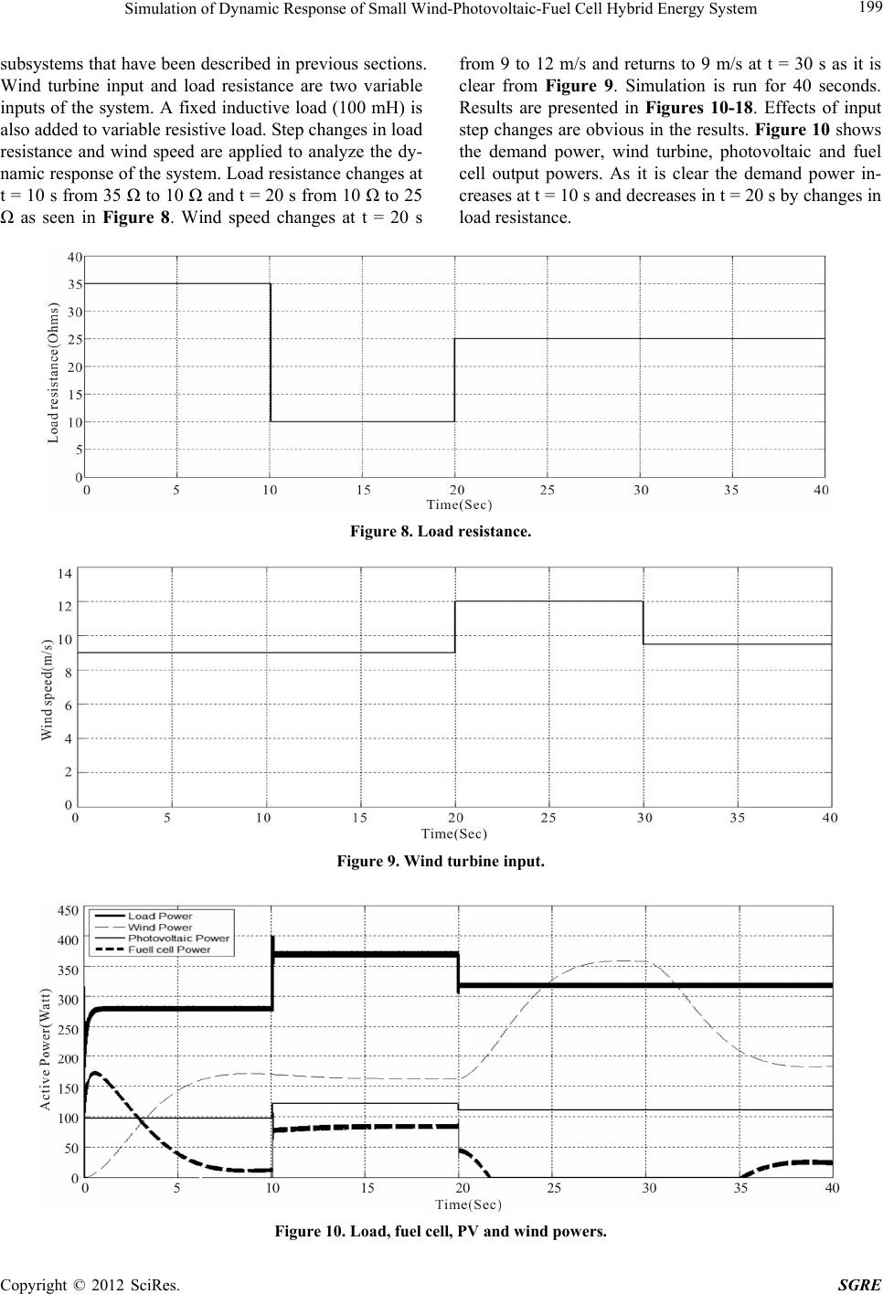
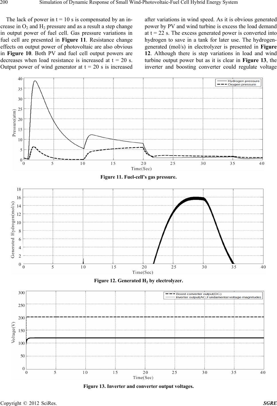
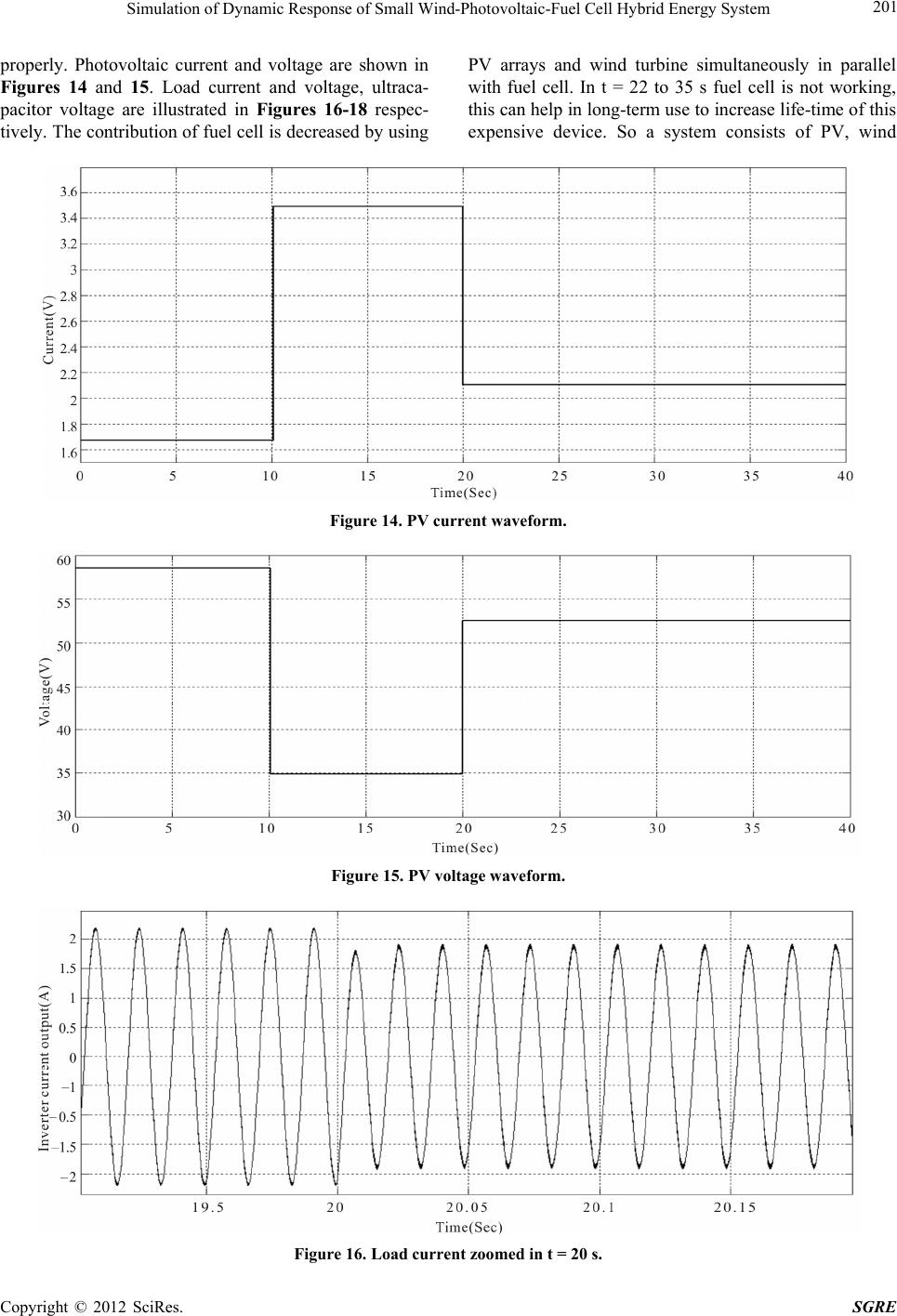
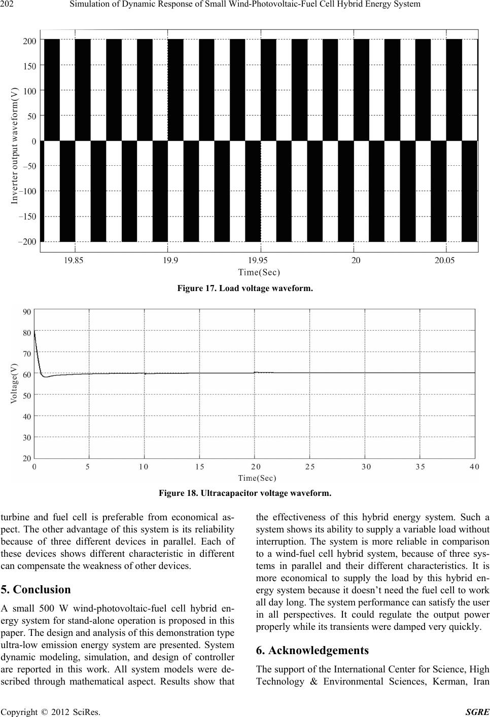
Simulation of Dynamic Response of Small Wind-Photovoltaic-Fuel Cell Hybrid Energy System 203
under grant No. 1/670 is gratefully acknowledged.
REFERENCES
[1] B. S. Borowy and Z. M. Salameh, “Optimum Photo-
voltaic Array Size for a Hybrid Wind/PV System,” IEEE
Transactions on Energy Conversion, Vol. 9, No. 3, 1994,
pp. 482-488. doi:10.1109/60.326466
[2] B. S. Borowy and Z. M. Salameh, “Methodology for
Optimally Sizing the Combination of a Battery Bank and
PV Array in a Wind/PV Hybrid System,” IEEE Transac-
tions on Energy Conversion, Vol. 11, No. 2, 1996, pp.
367-374. doi:10.1109/60.507648
[3] A. N. Celik, “Optimisation and Techno-Economic Analy-
sis of Autonomous Photovoltaic-Wind hybrid Energy
Systems in Comparison to Single Photovoltaic and Wind
Systems,” Energy Conversion and Management, Vol. 43,
No. 18, 2002, pp. 2453-2468.
doi:10.1016/S0196-8904(01)00198-4
[4] K. Agbossuo, R. Chahine, J. Hamelin, F. Laurencelle and
J. Hamelin, “Renewable Energy Systems Based on Hy-
drogen for Remote Applications,” Journal of Power
Sources, Vol. 96, No. 1, 2001, pp. 168-172.
doi:10.1016/S0378-7753(01)00495-5
[5] K. Agbossuo, J. Hamelin, A. Laperriere and F. Laur-
encelle, “Load Communication for Stand Alone Wind
and PV Hydrogen Energy System,” Proceedings of Ca-
nadian Conference of Electrical and Computer Engi-
neering, Vol. 1, 2000, pp. 555-558.
[6] A. Sathyan, K. A. Kiszynski and S. Al-Hallaj, “Hybrid
Wind/PV/Fuel Cell Generation System,” IEEE Confer-
ence on Vehicle Power and Propulsion, Chicago, 7-9
September 2005, pp. 495-500.
[7] F. Iannone, S. Leva and D. Zaninelli, “Hybrid Photo-
voltaic and Hybrid Photovoltaic-Fuel Cell System: Eco-
nomic and Environmental Analysis,” IEEE Power Engi-
neering Society General Meeting, San Francisco, 12-16
June 2005, pp. 1503-1509.
[8] T. F. El-Shatter, M. N. Eskander and M. El-Hagry, “En-
ergy Flow and Management of a Hybrid Wind/PV/Fuel
Cell Generation System,” Energy Conversion and Man-
agement, Vol. 47, No. 9-10, 2006, pp. 1264-1280.
doi:10.1016/j.enconman.2005.06.022
[9] D. Das, R. Esmaili, L. Xu and D. Nichols, “An Optimal
Design of a Grid Connected Hybrid Wind/Photovol-
taic/Fuel Cell System for Distributed Energy Production,”
31st Annual Conference of IEEE Industrial Electronics
Society, Raleigh, 6-10 November 2005, pp. 2499-2504.
[10] D. B. Nelson, M. H. Nehrir and C. Wang, “Unit Sizing
and Cost Analysis of Stand-Alone Hybrid Wind/PV/Fuel
Cell Power Generation Systems,” Renewable Energy, Vol.
31, No. 10, 2006, pp. 1641-1656.
doi:10.1016/j.renene.2005.08.031
[11] A. D. Hansen, P. Sorensen, L. H. Hansen and H. Binder,
“Models for a Stand-Alone PV System,” Riso National
laboratory, Roskilde, 2000.
[12] M. T. Iqbal, “Simulation of a Small Wind Fuel Cell Hy-
brid Energy System,” Renewable Energy, Vol. 28, No. 4,
2003, pp. 511-522.
[13] M. J. Khan and M. T. Iqbal, “Dynamic Modeling and
Simulation of a Small Wind-Fuel Cell Hybrid Energy
System,” Renewable Energy, Vol. 30, No. 3, 2005, pp.
421-439.
[14] M. R. Patel, “Wind and Solar Power Systems,” CRC
Press, Boca Raton, 1999.
[15] http://www.windenergy.com
[16] R. S. Garcia and D. Weisser, “A Wind-Diesel System
with Hydrogen Storage: Joint Optimization of Design and
Dispatch,” Renewable Energy, Vol. 31, No. 14, 2006, pp.
2296-2320. doi:10.1016/j.renene.2005.11.003
[17] J. C. Amphlett, R. M. Baumert, R. F. Mann, B. A. Pep-
pley, P. R. Roberge and T. J. Harries, “Performance
Modeling of the Ballard Mark IV Solid Polymer Electro-
lyte Fuel Cell,” Journal of the Electrochemical Society,
Vol. 142, No. 1, 1995, pp. 9-15. doi:10.1149/1.2043959
[18] R. F. Mann, J. C. Amphlett, M. Hooper, H. M. Jensen, B.
A. Peppley and P. R. Roberge, “Development and Appli-
cation of a Generalised Steady-State Electrochemical Mo-
del of a PEM Fuel Cell,” Journal of Power Sources, Vol.
86, No. 1-2, 2000, pp. 173-180.
doi:10.1016/S0378-7753(99)00484-X
[19] J. Larminie and A. Dicks, “Fuel Cell Systems Ex-
plained,” 2nd Edition, John Wiley and Sons, New York,
2001.
[20] http://www.mathworks.com
Copyright © 2012 SciRes. SGRE