Paper Menu >>
Journal Menu >>
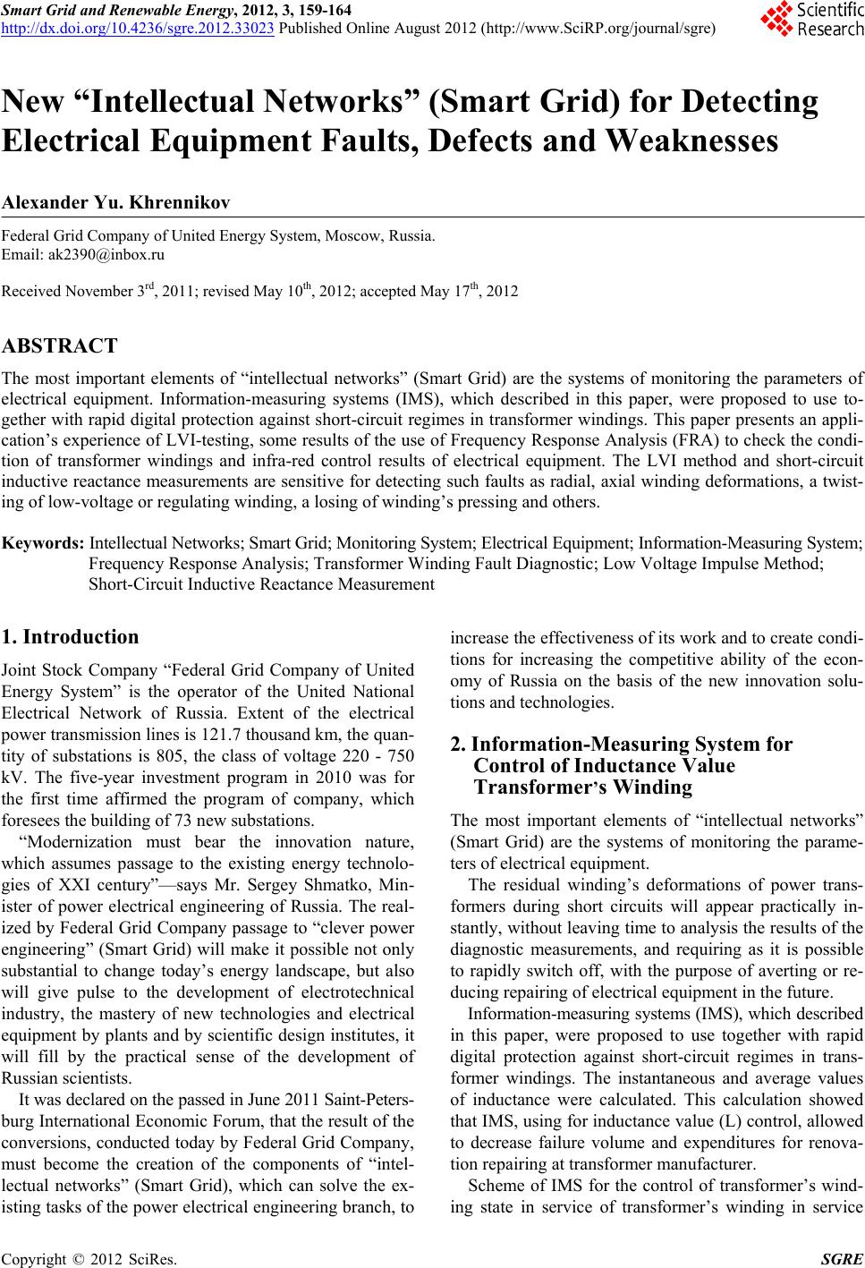 Smart Grid and Renewable Energy, 2012, 3, 159-164 http://dx.doi.org/10.4236/sgre.2012.33023 Published Online August 2012 (http://www.SciRP.org/journal/sgre) 159 New “Intellectual Networks” (Smart Grid) for Detecting Electrical Equipment Faults, Defects and Weaknesses Alexander Yu. Khrennikov Federal Grid Company of United Energy System, Moscow, Russia. Email: ak2390@inbox.ru Received November 3rd, 2011; revised May 10th, 2012; accepted May 17th, 2012 ABSTRACT The most important elements of “intellectual networks” (Smart Grid) are the systems of monitoring the parameters of electrical equipment. Information-measuring systems (IMS), which described in this paper, were proposed to use to- gether with rapid digital protection against short-circuit regimes in transformer windings. This paper presents an appli- cation’s experience of LVI-testing, some results of the use of Frequency Response Analysis (FRA) to check the condi- tion of transformer windings and infra-red control results of electrical equipment. The LVI method and short-circuit inductive reactance measurements are sensitive for detecting such faults as radial, axial winding deformations, a twist- ing of low-voltage or regulating winding, a losing of winding’s pressing and others. Keywords: Intellectual Networks; Smart Grid; Monitoring System; Electrical Equipment; Information-Measuring System; Frequency Response Analysis; Transformer Winding Fault Diagnostic; Low Voltage Impulse Method; Short-Circuit Inductive Reactance Measurement 1. Introduction Joint Stock Company “Federal Grid Company of United Energy System” is the operator of the United National Electrical Network of Russia. Extent of the electrical power transmission lines is 121.7 thousand km, the quan- tity of substations is 805, the class of voltage 220 - 750 kV. The five-year investment program in 2010 was for the first time affirmed the program of company, which foresees the building of 73 new substations. “Modernization must bear the innovation nature, which assumes passage to the existing energy technolo- gies of XXI century”—says Mr. Sergey Shmatko, Min- ister of power electrical engineering of Russia. The real- ized by Federal Grid Company passage to “clever power engineering” (Smart Grid) will make it possible not only substantial to change today’s energy landscape, but also will give pulse to the development of electrotechnical industry, the mastery of new technologies and electrical equipment by plants and by scientific design institutes, it will fill by the practical sense of the development of Russian scientists. It was declared on the passed in June 2011 Saint-Peters- burg International Economic Forum, that the result of the conversions, conducted today by Federal Grid Company, must become the creation of the components of “intel- lectual networks” (Smart Grid), which can solve the ex- isting tasks of the power electrical engineering branch, to increase the effectiveness of its work and to create condi- tions for increasing the competitive ability of the econ- omy of Russia on the basis of the new innovation solu- tions and technologies. 2. Information-Measurin g System for Control of Inductance Value Transformer’s Winding The most important elements of “intellectual networks” (Smart Grid) are the systems of monitoring the parame- ters of electrical equipment. The residual winding’s deformations of power trans- formers during short circuits will appear practically in- stantly, without leaving time to analysis the results of the diagnostic measurements, and requiring as it is possible to rapidly switch off, with the purpose of averting or re- ducing repairing of electrical equipment in the future. Information-measuring systems (IMS), which described in this paper, were proposed to use together with rapid digital protection against short-circuit regimes in trans- former windings. The instantaneous and average values of inductance were calculated. This calculation showed that IMS, using for inductance value (L) control, allowed to decrease failure volume and expenditures for renova- tion repairing at transformer manufacturer. Scheme of IMS for the control of transformer’s wind- ing state in service of transformer’s winding in service Copyright © 2012 SciRes. SGRE 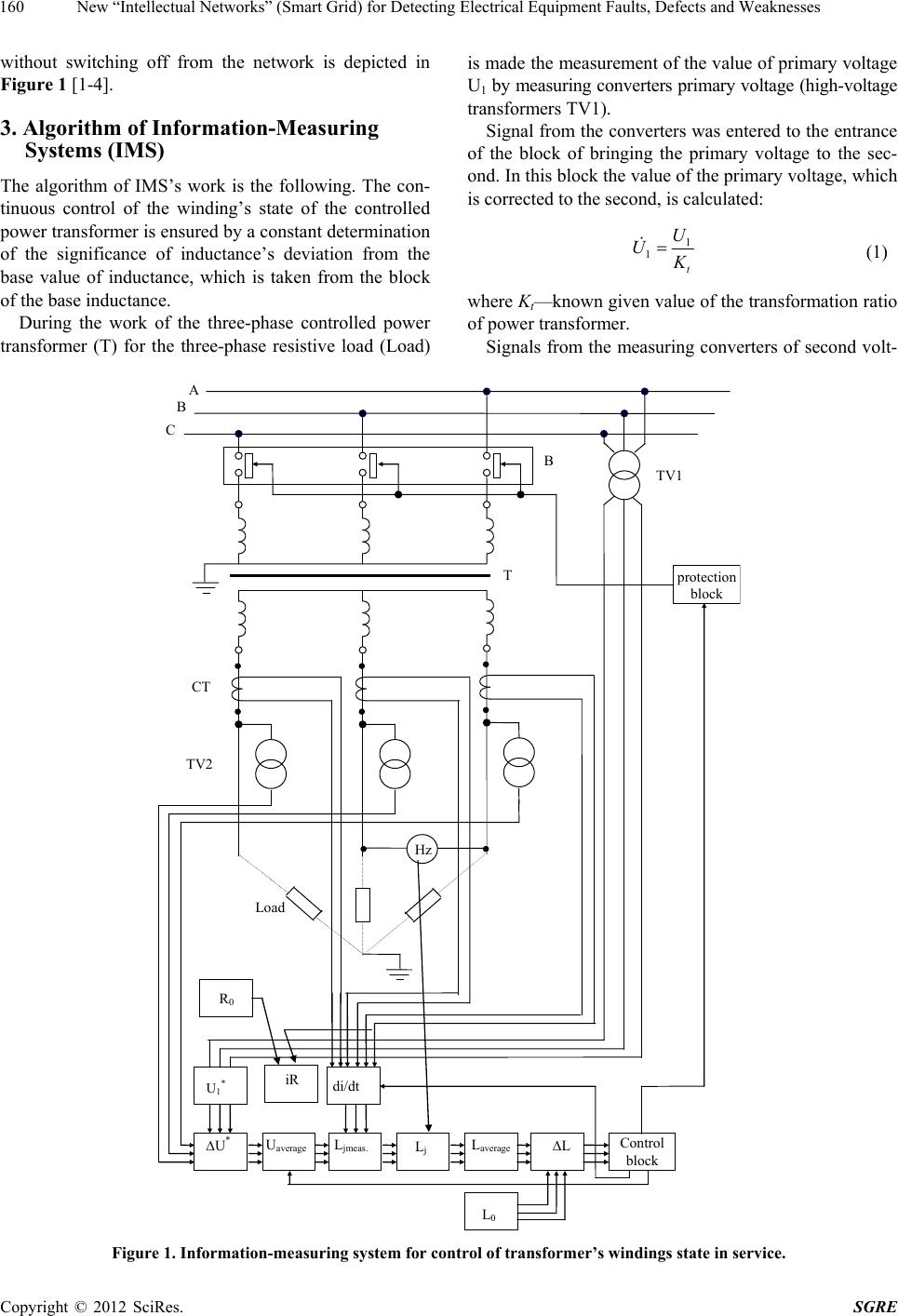 New “Intellectual Networks” (Smart Grid) for Detecting Electrical Equipment Faults, Defects and Weaknesses 160 without switching off from the network is depicted in Figure 1 [1-4]. 3. Algorithm of Information-Measuring Systems (IMS) The algorithm of IMS’s work is the following. The con- tinuous control of the winding’s state of the controlled power transformer is ensured by a constant determination of the significance of inductance’s deviation from the base value of inductance, which is taken from the block of the base inductance. During the work of the three-phase controlled power transformer (T) for the three-phase resistive load (Load) is made the measurement of the value of primary voltage U1 by measuring converters primary voltage (high-voltage transformers TV1). Signal from the converters was entered to the entrance of the block of bringing the primary voltage to the sec- ond. In this block the value of the primary voltage, which is corrected to the second, is calculated: 1 1 t U U K (1) where Kt—known given value of the transformation ratio of power transformer. Signals from the measuring converters of second volt- Control block protection b loc k ТV2 CТ А В С В ТV1 Т Hz Load di/dt Uaverage L0 L Laverage Lj Ljmeas. U* U1* iR R0 Figure 1. Information-measuring system for control of transformer’s windings state in service. Copyright © 2012 SciRes. SGRE  New “Intellectual Networks” (Smart Grid) for Detecting Electrical Equipment Faults, Defects and Weaknesses 161 age (voltage transformers TV2) and signals from the output of the previous block were entered to the entrance. In the block of calculation of voltage difference, which corrected to the second side, is determined: 1 UUU 2 (2) where U2—the value of second voltage, measured by converters TV2. The calculation is produced in the assigned time inter- val in the block of calculation of voltage’s average value: 2 average 2 jj ut ut u 1 (3) where j u —value between corrected to the second side voltages on the transformer; t1 and t2—temporary bounda- ries of partition’s interval. In the block of calculation of the current derivation is calculated the increase of the current in the assigned time interval: 2 21 jj j it it di dttt 1 (4) ij—value of current in the secondary winding of con- trolled transformer, measured by current converters (cur- rent transformers CT). In the block of calculation of inductance the instanta- neous value of inductance is determined in the assigned time interval: average meas.j j u Ldi dt (5) where average—average value of voltage, u j didt —va- lue of current derivation. Equation (5) can be obtained from Ohm’s law for the magnetic circuit: Li (6) Further using expressions: ; d uL dt i , (7) we obtain dLdiidL . Disregarding second term (L = const), we have with the linear characteristic of the medium: di uL dt (8) which is analogous to (5). In the block of bringing the value of inductance to the nominal frequency the instantaneous value of inductance, with corrected to the nominal frequency, is calculated: meas. meas. nom. jj f LL f (9) where: meas. f —measured by frequency converter value of the frequency (Hz), nom. f —nominal value of the fre- quency. —instantaneous value of inductance. meas .j In the following block the average value of inductance during each period is calculated: L average 1 N j j LL N (10) In the block of calculation of deviation is produced the comparison of Laverage value during the period with the base L0 value and their difference is calculated: average 0 0 100%LL LL (11) average —the average value of inductance during the period; L L0—the base value of transformer inductance, deter- mined by calculations also according to the results of preliminary experiment. In the case of the beginning of winding deformations, and also in the case of winding turn-to-turn internal short- circuit the value of inductance L is developed to increase, or to decrease from this period to next period that ac- companies the irreversible destruction of the controlled power transformer’s windings. Then the signal from the control block enters to the protection block (rapid digital protection), where signal to switch off in high-voltage circuit breaker (B) is formed. And then Information-measuring system and connected with it protection block stopped the process of winding destruction [1-4]. 4. Short-Circuit Testing of Power Transformers and LVI Method for Detecting Transformer’s Winding Deformations Power transformers are one of the basic parts in the cir- cuitry of power transmission and delivery. Therefore the interest to perfection of the power transformers’ fault diagnostic methods is being increased. The repairing of power transformers and other electrical equipments are carried on, using diagnostic measurement results [5-7]. Infra-red control was used for detecting electrical equipment’s faults, defects and weaknesses. There are main causes of power transformer winding faults: high-voltage bushing damage, breakage of wind- ing insulation after long time service factors and partial discharge intensity, insufficient electrodynamic winding strength during short-circuits. LVI-testing, FRA and short-circuit inductive reactance measurements are sensitive to detecting such transform- ers winding faults as buckling, axial shift and others. 180 units of 25 - 240 MVA 110 - 500 kV power transformers Copyright © 2012 SciRes. SGRE  New “Intellectual Networks” (Smart Grid) for Detecting Electrical Equipment Faults, Defects and Weaknesses 162 were checked by low voltage impulse (LVI) method. A few power transformers were detected with winding de- formations after short-circuit with aperiodical short-circuit current. The block 80 MVA 110 kV transformer had se- rious amplitude and frequency LVI LV1-LV2 winding oscillogram differences after generator side short-circuit. The low-voltage (LV) winding FRA spectrum of 80 MVA 110 kV transformer changed after short-circuit. 22 units of power transformers extending in capacity range from about 25 MVA to over 666 MVA and in voltage range from 110 kV to 750 kV were tested at short-circuit at Togliatti Power Testing Laboratory dur- ing 1983-1995. The application of LVI method and mea- surement of inductive reactance deviation allowed to detect a twisting of low-voltage winding and radial winding’s deformations at tests of the 400 MVA and a 250 MVA block power transformers [4-9]. The damage of regulating winding was detected at the short-circuit tests of link 167 MVA/500 kV/220 kV and 125 MVA/220 kV/110 kV autotransformer at Power Test- ing Laboratory. The regulating winding was untwisted at short-circuit tests of 25 MVA railway transformer. The windings of 160 MVA metallurgical transformer were pressed off during these tests. Deformations of turns were detected at the electrodynamic tests of 666 MVA power transformer for the Hydroelectric Power Station. 5. An Example of Transformer’s Winding LVI-Testing The LVI method is very sensitive to small local changes of winding mechanical condition: turn-to-turn and coil- to-coil capacitances, mutual inductances between trans- former windings. The LVI oscillogram, which contains basic resonance frequencies of transformer winding, is a “fingerprint” or state of transformer. Generally, windings of large power transformers have three basic resonance frequencies. Frequency Response Analysis (FRA) showed presence of 110 kHz, 320 kHz and 550 kHz frequencies for 250 MVA/220 kV transformer. An amplitude of these resonance frequencies changed 1.3 - 2 times after detec- tion of radial buckling in LV winding at short-circuit tests (Figure 2) [10-12]. Inductive reactance deviation was Xk = +1% in this case. The axial shift and damage of pressing system with short-circuit to iron core were detected in the B phase LV internal winding of 250 MVA/220 kV transformer after short-circuit tests (Figure 3). Inductive reactance devia- tion was Xk = +20% on the B phase. Radial buckling in MV 220 kV winding (a) and in HV 500 kV winding (b) of 167 MVA/500 kV/220 kV auto transformer after three short-circuits in service is in the Figure 4. 125 MVA/220 kV/110 kV autotransformer was switched Figure 2. Typical example of deformation due to radial buckling in the A phase LV internal winding of 250 MVA/ 220 kV transformer ( Xk = +1%). (a) (b) Figure 3. Example of deformation due to axial shift (a) and damage of pressing system with short-circuit to iron core (b) in the B phase LV internal winding of 250 MVA/220 kV transformer ( Xk = +20%). Copyright © 2012 SciRes. SGRE  New “Intellectual Networks” (Smart Grid) for Detecting Electrical Equipment Faults, Defects and Weaknesses 163 off by gas relay protection after internal short-circuit at the substation in service. The tank of autotransformer was not deformed (Figure 5). Serious deformations and turn-to-turn internal short-circuit were detected in MV 110 kV winding, regulating winding and LV winding by LVI-testing, short-circuit inductive reactance measure- ments and iron core losses methods. LVI oscillograms of MV 110 kV winding, including turns of regulating wind- ing (a), and oscillograms of LV winding (b) are in the Figure 6. The LVI amplitude-frequency differences of C phase from A and B phases are noticeable. The short- circuit inductive reactance differences of C phase from A and B phases are Xk = –11.6% in MV-LV winding regime, and Xk = –7% in HV-LV winding regime. The main goal of diagnostic investigation of 125 MVA/ 220 kV/110 kV autotransformer was to define the possi- bility of repairing. On the basis of results of this diagnostic investigation there was planed the substitution of auto- transformer [8,10-15]. 6. Application of FRA Method The block 80 MVA 110 kV transformer had serious MV (a) HV (b) Figure 4. An example of radial buckling in MV 220 kV winding (a) and in HV external 500 kV winding (b) of 167 MVA/500 kV/220 kV autotransformer after three short- circuits at 500 kV substation in service. Figure 5. 125 MVA/220 kV/110 kV autotransformer after internal short-cirat at 220 kV substation. (a) (b) Figure 6. LVI oscillograms of MV 110 kV winding, in- cluding turns of regulating winding (a), and oscillograms of LV winding (b) of 125 MVA/220 kV/110 kV autotrans- former after internal short-circuit at 220 kV substation, illustrating amplitude-frequency differences of C phase . amplitude and frequency LVI-changes in the LV1-LV2 winding oscillogram differences after generator side short-circuit at Heat Electric Power Station. The FRA signal spectrum of 80 MVA 110 kV transformer changed after short-circuit. The original 300 kHz, 500 kHz, 700 kHz resonance frequencies disappeared and a new 400 kHz, 800 kHz resonance frequencies appeared. The FRA spectrum analysis of 80 MVA 110 kV transformer’s LV-windings detected axial electrodynamic deformations [4,9-11,13,15]. Diagnostics experience was showed that the trans- former plant documentation should be included: normo- grams of LVI-testing, FRA spectrum, data bases of par- tial discharge technique, normograms of infra-red diag- nostics (for first models) during heat testing, data bases of winding pressure by vibration measurements of trans- former. Short-circuit reactance measurements (Zk) and LVI-testing should be carried out together. The necessity of LVI-normograms of all new manufactured transformer with capacity over 2.5 MVA, which are produced at the transformer manufacturers, is caming. It’s necessary for data bases of the mechanical winding conditions for the future LVI-testing at the energy system after probable short-circuit. The first examples are normograms of LVI-testing of 125 MVA 220/110 kV. Autotransformer, 250 MVA/110 kV transformer for the Heat Electric Power Station, which carried out after repair with the winding change at the transformer manu- facturer. The normograms of LVI-testing of new 6.3 MVA/110 kV transformer were recorded. LVI-testing is necessary for all transformers after short-circuits, for new Copyright © 2012 SciRes. SGRE  New “Intellectual Networks” (Smart Grid) for Detecting Electrical Equipment Faults, Defects and Weaknesses Copyright © 2012 SciRes. SGRE 164 transformers, for transformers after repairs at all energy systems [4,9,10,15]. 7. Conclusions The most important elements of “intellectual networks” (Smart Grid) are the systems of monitoring the parame- ters of electrical equipment. The residual winding’s deformations of power trans- formers during short circuits will appear practically in- stantly, without leaving time on the analysis of the results of the diagnostic measurements, and requiring as it is possible to rapidly switch off, with the purpose of avert- ing or reducing repairing of electrical equipment in the future. Information-measuring systems, which described in this paper, were proposed to use together with rapid digital protection against short-circuit regimes in trans- former windings. At the beginning of winding deformations, and also in the case of winding turn-to-turn internal short-circuit the value of inductance L is developed to increase, or to de- crease. Information-measuring system and connected with it protection block stopped the process of winding destruc- tion. The low voltage impulse testing is a very sensitive and reliable method of deformation’s detections of transformer windings. The LVI oscillograms is a “fingerprint” of transformer. This winding “fingerprint” is defined by major reso- nance frequencies (a winding spectra). The 250 MVA 220 kV winding transformer’s spectra contained a 110 kHz, 320 kHz and 550 kHz frequencies, which are changed 1.3 - 2 times after the mechanical radial winding deformations. The LV-winding FRA spectrum of 80 MVA 110 kV transformer changed after short-circuit. The original 300 kHz, 500 kHz, 700 kHz resonance fre- quencies disappeared and a new 400 kHz, 800 kHz reso- nance frequencies appeared. REFERENCES [1] A. Yu. Khrennikov, “Control and Protection Device of Transformer Windings against Deformation at Short Cir- cuits,” Patent of Russian Federation, No. 2136099, Bulle- tin No. 24, 1999. [2] A. Yu. Khrennikov, O. A. Shlegel and S. I. Lurie, “Con- trol and Protection Device of Transformer Windings against Deformation at Short Circuits in Service,” Patent of Russian Federation, No. 2063050, Bulletin No. 18, 1996. [3] A. Yu. Khrennikov, “Measuring Device of the Inductive Transformer Short-Circuit Impedance,” Patent of Russian Federation, No. 96110718А, 1998. [4] A. Yu. Khrennikov, “Complex Diagnostic Modeling of Technical Parameters of Power Transformer-Reactor Electrical Equipment Condition,” Ph.D. Thesis, Samara University, Samara Oblast, 2009. [5] A. Yu. Khrennikov and O. A. Shlegel, “Extra High Volt- age Transformer Short Circuit Steadiness Test Results and Their Effect on Calculations and Design,” Reports of 9th International Power System Conference, St. Peters- burg, Vol. 2, 1994, pp. 1-121. [6] T. Fogelberg and R. S. Girgis, “ABB Power Transformers: A Result of Merging Different Technologies with Pros- pects for Significant Future Advancements,” Interna- tional Simposium “Electrotechnics 2010”, Moscow, Vol. 1, 1994. [7] V. Balakrishnan, “A Study of Short-Circuits in Large Power Transformers,” Elect rical In dia, Vol. XXIX, No. 4, 1989. [8] W. Lech and L. Tyminski, “Detecting Transformer Wind- ing Damage—The Low Voltage Impulse Method,” Elec- trical Review, No. 18, 1966. [9] W. J. McNutt, W. M. Johnson, R. A. Nelson and R. E. Ayers, “Power Transformen Short-Circuit Strength—Re- quirements, Design, and Demonstration,” IEEE Trans- actions on Power Apparatus and Systems, No. 8, 1970, pp. 1955-1969. doi:10.1109/TPAS.1970.292780 [10] R. Malewski, A. Yu. Khrennikov, O. A. Shlegel and A. G. Dolgopolov, “Monitoring of Winding Displacements in HV Transformers in Service,” Reports of CIGRE Working Group 33.03, Padua, 4-9 September 1995. [11] A. Yu. Khrennikov, “Short-Circuit Performance of Power Transformers. Test Experience at Samaraenergo Co. and at Power Testing Station in Togliatti, including Fault Di- agnostics,” Reports of CIGRE Study Commitee 12 Trans- formers, Budapest, 14-17 June 1999. [12] A. Yu. Khrennikov, “Power Transformer’s Fault Diagnos- tics at SAMARAENERGO Co., including FRA/LVI Me- thod,” Reports from School of Math, and System Engi- neering, Vaxjo University, Småland, No. 43, 2000. [13] A. Yu. Khrennikov, “Short-Circuit Performance of Power Transformers. Transformer Testing Experience for Re- liability’s Increase of Electric Power Supply,” Reports of CIGRE Colloquium, Comitee A2, Moscow, 19-24 June 2005. [14] A. Yu. Khrennikov, V. G. Goldshtein and A. A. Sklad- chikov, “The Analysis of a Condition of Overhead Lines of Power Transmission 6 - 500 kV,” Power Plants, No. 5, 2010. [15] A. Yu. Khrennikov and V. G. Goldshtein, “The Technical Diagnostics, damages and Resource of Power and Meas- urement Transformers, Reactors,” Energo Atomizdat, 2007, 319 p. |