Paper Menu >>
Journal Menu >>
 Wireless Sensor Network, 2010, 2, 555-561 doi:10.4236/wsn.2010.27067 Published Online July 2010 (http://www.SciRP.org/journal/wsn) Copyright © 2010 SciRes. WSN Performance Analysis of Downlink MIMO WCDMA Systems Using Antenna Selection in Transmitter and MRC Plus LDD in Receiver over Correlated Nakagami-Fading Channels Siavash Ghavami1, Mahmood Mohassel Feghhi2, Bahman Abolhassani2 1School of Electrical & Computer Engineering, University of Tehran, Tehran, Iran 2School of Electrical Engineering, Iran University of Science and technology, Tehran, Iran E-mail: s.ghavami@ece.ut.ac.ir, mmohaselfeghhi@ee.iust.ac.ir, abolhassani@iust.ac.ir Received April 9, 2010; revised May 4, 2010; accepted May 12, 2010 Abstract In this paper bit error rate (BER) performance is analyzed for multiple input-multiple output (MIMO) com- munications systems using antenna selection in the transmitter, maximal ratio combining (MRC) and linear de-correlating detector (LDD) in the receiver in wide band code division multiple access (WCDMA) downlink channels with correlated Nakagami fading. The MRC maximizes signal to noise ratio of the re- ceived signal, then the LDD cancels out multiple access interference (MAI). Theoretical results are validated using computer simulations. Moreover, a pilot based estimation method is proposed to jointly estimate the channel gains and the rows of the LDD operator. Simulation results show that using this proposed method, diversity order is maintained in the receiver. Furthermore, our analysis shows the spectral efficiency degra- dation due to the pilot based strategy is negligible. Keywords: MIMO, Transmitter Antenna Selection, WCDMA, Maximum Ratio Combining 1. Introduction Wide band code division multiple accesses (WCDMA) has been proposed to satisfy ever-increasing demands for higher data rates, as well as to allow more users to sim- ultaneously access the network [1]. So, it is employed in the third generation mobile networks to provide multi- media services with required qualities. Multiuser detec- tors (MUDs) are used to detect the desired signal and to simultaneously cancel out interferences coming from co- users in WCDMA systems [2]. In downlink scenario, blind multiuser detectors are proposed for multiple ac- cess interference (MAI) cancellation [3], but use of these detectors increases computational complexity of mobile stations (MSs). Another approach for MAI cancellation in downlink multiuser scenario is the precoding method at the base station (BS) [4], but it requires error free links between each MS and the BS, which is not the case in practical scenarios. Multiple input-multiple-output (MIMO) systems sig- nificantly increase system capacity and improve perfor- mance [5,6] at the cost of increasing hardware complex- ity by increasing the number of transmitting and receiv- ing antennas. Transmitter antenna selection (TAS) can reduce the cost of multiple antennas and at the same time can retain many advantages of MIMO systems. A com- bined transmitter antenna selection and maximal ratio combining (MRC) has been proposed in [7]. This method selects the transmitter antenna that maximizes the total received signal power at the receiver. Inactivating other transmitter antennas reduces the hardware complexity; furthermore, this method reduces the number of radio channels used in a MIMO system. Bit error rate (BER) performance of this method has been analyzed in inde- pendent and correlated Rayleigh fading channels, respec- tively in [8] and [9]. As well, recently a BER perform- ance analysis of TAS/MRC has been studied in corre- lated Nakagami fading channels [10], however it is for a single user scenario in a non CDMA system. In this paper, the downlink scenario of MIMO WCD- MA systems using TAS/MRC plus LDD has been stud- ied. MIMO is a strong tool for capacity increasing and performance improvement. But the limitation in the size of a MS necessitates employing receiver antennas with a  S. GHAVAMI ET AL. Copyright © 2010 SciRes. WSN 556 small distance among them; therefore the correlation among channel gains should be considered even in rich scattering environments. For hardware complexity re- duction and keeping diversity order in the base station, TAS in the transmitter is a good candidate, which is con- sidered in this paper. Furthermore for reducing effect of MAI, a linear de-correlating detector (LDD), which is a sub optimum multi user detector, is used in the receiver. The LDD has simple structure with good performance for MAI mitigation [2]. In this paper, the BER perform- ance of a downlink WCDMA system in the correlated Nakagami fading channels is analyzed, and theoretical results are validated using computer simulations. MAI cancellation using MUDs needs to know the user’s and co-users’ spreading sequences, which increases the com- plexities of MSs. In this paper, we consider the case in which the links between each MS and the BS are error prone. So, precoding techniques can not be applied. Fur- thermore, we give up the blind MUDs for their high computational complexities [11]. In this paper, we pro- pose a low complexity pilot based channel estimation method for the joint estimation of the channel gains and the rows of the LDD operator in order to cancel out the MAI. The proposed method does not require the spread- ing sequences of all active users (which are not available in the MS), as well as the calculation of the inverse cross correlation matrix. So, using this estimation method, the MSs can cancel out the MAI with-out prior knowledge about spreading sequences of co-users by decorrelating users’ signals. The remaining of this paper is organized as follows. In Section 2, system models are considered. BER perform- ance analysis has been presented in Section 3. Joint es- timation of channel and the LDD operator is proposed in Section 4. Simulation results are presented in Section 5 in order to validate our performance analysis and evalu- ate the performance of our proposed joint estimation method. Finally conclusions are presented in Section 6. 2. System Model We consider the downlink scenario of a WCDMA sys- tem. The jth antenna of the MS receives signals of K users which have been sent by the ith transmitter antenna in the base station. It is given by ,,, 1 ()[] ()(), K ijk kijsij kl rtAdlhtlT nt (1) where Ak, dk[l], Ts and ,ij are, respectively, the re- ceived amplitude, lth data symbol of kth user, symbol period and path delay between ith transmitter antenna and jth receiver antenna and ()nt is additive white Gaussian noise. The ,ij h is expressed by: 1 ,, 0 1 ()[ ](), N ijk ijc m ht cmptmT N (2) where N is the processing gain, c TTN is the chip time, ,() ij pt is the convolution of three components: the chip pulse shaping waveform, the channel filter be- tween the ith transmitter antenna and the jth receiver antenna (which represents the channel echoes) and the receiver filter, with unit energy. [] k cm is the value of the mth chip of kth user’s spreading sequence with [] 1 k cm . Data symbols [] k dl of different users are independent with identical distributions (i.i.d). The channel between the ith transmitter and the jth receiver antenna denotes as ,() ,, ()() ij j t ij ij tte , is assumed to be a quasi-static fading and its envelope ,() ij t follows Nakagami-m distribution , 2 21 2 ()exp( ) ij m m mmx px x m (3) where 2 22 ,ij mE , 2 ,ij E , 1 0 nu nuedu . Therefore2 ,,ij ij has gamma distribution, , 1 ()exp(). ij mm mx mx px m (4) 2.1. Transmitter Antenna Selection The TAS is performed so that the total received signal power is maximized. Mathematically, it is equivalent to selection antenna such that: 2 , 11 arg max. r t L sij iL j i (5) The MS sends s iusing only 2 log () t L bits, where denotes ceiling operation. In performance analysis, channel estimation is assumed to be performed perfectly at the receiver, also the feedback link between the re- ceiver and the transmitter is considered to be perfect and without delay (using forward error correction (FEC) it is possible to send a few flag bits, i.e., 2 log () t L , without error even in error prone link). The size of a Ms limits the use of antenna diversity and this makes the channels correlated. The covariance matrix among channel power gains, e.g., ,1 , ... ss sr T ii iL δ in the receiver is  S. GHAVAMI ET AL. Copyright © 2010 SciRes. WSN 557 given by , ss H ii EΩδδ (6) where, Eand H , respectively denote expectation and Hermitian operations. 2.2. BER Performance Analysis In this section, BER performance of TAS/MRC plus LDD in the downlink scenario of WCDMA systems is analyzed. In the following, a bold capital letter denotes a matrix (A), a bold small letter denotes a vector (a), and an unbolded letter denotes a scalar (a or A). Samples of the channel are considered to be constant for each sym- bol; such that for the lth symbol defined as ,, []( ) ij ij llT . Defining 1 diag( ,...,) k A AA, 1 [, ...] TT K Cc,c , 0.5 ...,[0],[ 1] kkk ccNN c, 1 [][],..., []T K ldldld and 01 [][],...,[] j T N j lnlnl n , which contains the noise samples in the jth receiver an- tenna, the received signal form the ith transmitter an- tenna to the jth receiver antenna is given by ,, [][][] []. ij ij llll CAdrn (7) For any linear detector combined with MRC, the deci- sion variable, ˆ[]l d is obtained by a linear combination of ,[] ij lr, i.e., * ,, 1 ˆ[]sign{Re([][]))}, r L ij ij j lll dDr (8) where the matrix D represents the operation of the mul- tiuser detector. For the LDD, D is the Moore-Penrose generalized inverse of the code matrix C [2], given by T1T 1T LDD () , DCCCRC (9) where T R=C C is a KK matrix containing the autocorrelation coefficients of the users’ spreading codes. In (9), it is assumed that K users’ codes are linearly in- dependent, to guarantee the existence of 1 R. The re- ceiver output is obtained as follows -1 * , 1 2 -1 -1 , 1 2-1 , 1 v[ ]C[ ] [ ] []CCA []C[] []A[]C[] . r r r L T ij j L TT ij j L T ij j lll lll ll l Rr RdRn dRn (10) The 1 , () 1 kkk R is the noise enhancement fac- tor produced by the de-correlating operation, therefore noise variance in the receiver side is increased to 22 ,nLDDkn , where 2 n is variance of []ln, which is equal to 02N. In the first step of the BER performance analysis, the probability density function (PDF) of maximum channel gains, which has been selected by criterion given by (5) must be obtained, max 1 max t i iL , where , 1 r L iij j . The PDF of max is obtained as [12] max 1 ()( ())() t ii L t pxLFx fx , (11) where () i F x and () i f x are respectively, the cumula- tive distribution function (CDF) and PDF of i . () i F x and () i f x for multi user scenario over correlated Na- kagami fading channels are extracted similar to those of a single user scenario over correlated Nakagami fading channels, which proposed in [10]. The TAS in the transmitter and MRC in the receiver increase the received SNR of kth user to 2 1 || r s L kk ij i , (12) in which 2 kbkn E , where b E is average energy per bit in the transmitter. For the BPSK modulation the instantaneous BER of the kth user is obtained as 2k Q , where Q is the Q-function. The BER is obtained by integration of instantaneous BER from zero to infinity, as [13] , 0(2)( ) k ekkkk PQpd . (13) Since k in (12) is kmax , the PDF of k is also obtained similar to (11), e.g., max () () k pp . Hence, calculation of integral in (13) can be performed using max ()p . Calculation of above integral, which is related to BER performance of multi-user scenario, is similar to the calculation of BER performance in a single user sce- nario, which has been performed in [10]. The final BER is obtained as (14), where, ! denotes the factorial opera- tion and ,1 lr lL are the eigenvalues of the matrix m. As well, lr is defined as (15), and the ex- pressions of ,, j jj abc can be obtained using the multi- nomial theorem [14]. 3. Joint Estimation of Channel Gains and LDD Operator In this section, effect of joint estimation of the channel gains and the rows of the LDD operator is investigated.  S. GHAVAMI ET AL. Copyright © 2010 SciRes. WSN 558 (1) (1)( 1) 2 , 11 00 1 00 12! 1 () () 1 21 j j tr r j cr mm cr LL Lm lrlb l ek tjj r lrj jl lbjlk s cr j sbl sbjlk E PLa cr b rEb N cr sE sEb N (14) 1, 1/ 1, 1(1 ), ()!() 0, r l m L k kkl i mr m lrk s mr mr kl l rm d s rm mr ds rm (15) In the downlink scenario of a WCDMA system, each MS knows only its own spreading sequence and doesn’t have any knowledge about spreading sequence of any other user, however using the LDD in the receiver needs the knowledge of spreading sequences of all other active users. Moreover, even if a mobile user knows the code matrix of all users (e.g., C) it needs to calculate the in- verse cross correlation matrix among spreading se- quences of all active users (e.g., 1- R), which has high computational complexity. Furthermore, the mobile user is allowed to detect only its own data. On the other hand, the total LDD D is not required in the mobile. And the kth user requires only the kth row of the LDD D denoted by L DD k D in the lth detected data as can be seen in the following equation 2 , 1 v[][][] [], r LDD L k kij j llll DCAdn (16) where [][] LDD k ll nDn . To obtain L DD k D in the receiver, in this paper, a new method is proposed, in which the base station sends L DD k D through a pilot signal. In the proposed method, the base station transmits the L DD k D periodically, whose period is much larger than the sym- bol time since the number of mobile users changes much slower than the symbol time. Moreover, the base station spreads the pilot signal for transmitting L DD k D using the kth spreading sequence. This strategy avoids generating interference and maintains the system security since only the kth mobile user can obtain the L DD k D for detecting its data. The received pilot symbol is as follows: ,[] , s pilot jkijk Al k rcFn (17) where k L DD k k Fc D, k n=c n and denotes element by element multiplications of two vectors. If 1 k A then p ilot j r will be equal to ,[] s ij l k Fn. Fig- ure 1 shows block diagram of the proposed strategy for joint channel and LDD operator estimation, in which TSk [l] denotes lth symbol of the training sequence of kth user. Training sequences for LDD operator estimation have been sent in non-overlapping time slots, hence MAI is not produced due to the transmission of pilot signals. If the pilot symbols length of each user increases, the effect of n in (17) reduces and a better estimation of L DD k D can be exploited. Error reduction of L DD k D esti- mation is obtained at the expense of increasing the train- ing duration from NTs to qNTs, where q is the number of pilot symbols repetition for the desired user. In the feedback link, ,[] s ijk l F is sent from the mo- bile user to the base-station to be used for the TAS. Since, Fk is known at the base-station, ,[] s ij l can be easily calculated at the base-station. Exactly like the previous section, feedback link is assumed to be error free and without any delay. Using pilot based strategy for joint estimation of chan- nel gains and LDD operator reduce the spectral effi- ciency. Hence, effect of using pilot based strategy on the spectral efficiency is analyzed in this section. The spec- tral efficiency of joint estimation of channel and LDD operator is defined as, 1, b TIB qK TTB R (18) 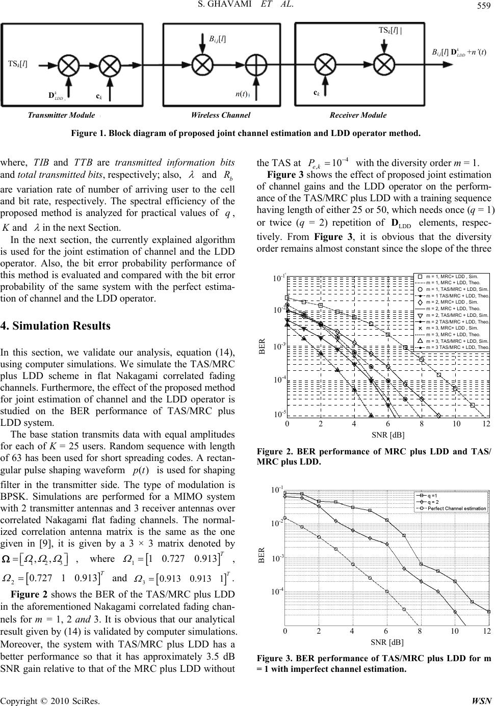 S. GHAVAMI ET AL. Copyright © 2010 SciRes. WSN 559 TS k [l] k LDD D c k n(t)c k TS k [l] Β i,j [l] Β i,j [l] k LDD D +n’(t) Transmitter Module Wireless Channel Receiver Module Figure 1. Block diagram of proposed joint channel estimation and LDD operator method. where, TIB and TTBare transmitted information bits and total transmitted bits, respectively; also, and b R are variation rate of number of arriving user to the cell and bit rate, respectively. The spectral efficiency of the proposed method is analyzed for practical values of q, K and in the next Section. In the next section, the currently explained algorithm is used for the joint estimation of channel and the LDD operator. Also, the bit error probability performance of this method is evaluated and compared with the bit error probability of the same system with the perfect estima- tion of channel and the LDD operator. 4. Simulation Results In this section, we validate our analysis, equation (14), using computer simulations. We simulate the TAS/MRC plus LDD scheme in flat Nakagami correlated fading channels. Furthermore, the effect of the proposed method for joint estimation of channel and the LDD operator is studied on the BER performance of TAS/MRC plus LDD system. The base station transmits data with equal amplitudes for each of K = 25 users. Random sequence with length of 63 has been used for short spreading codes. A rectan- gular pulse shaping waveform ()pt is used for shaping filter in the transmitter side. The type of modulation is BPSK. Simulations are performed for a MIMO system with 2 transmitter antennas and 3 receiver antennas over correlated Nakagami flat fading channels. The normal- ized correlation antenna matrix is the same as the one given in [9], it is given by a 3 × 3 matrix denoted by 123 ,, , where 110.7270.913 T , 20.72710.913T and 30.9130.9131 T . Figure 2 shows the BER of the TAS/MRC plus LDD in the aforementioned Nakagami correlated fading chan- nels for m = 1, 2 and 3. It is obvious that our analytical result given by (14) is validated by computer simulations. Moreover, the system with TAS/MRC plus LDD has a better performance so that it has approximately 3.5 dB SNR gain relative to that of the MRC plus LDD without the TAS at 4 ,10 ek P with the diversity order m = 1. Figure 3 shows the effect of proposed joint estimation of channel gains and the LDD operator on the perform- ance of the TAS/MRC plus LDD with a training sequence having length of either 25 or 50, which needs once (q = 1) or twice (q = 2) repetition of LDD D elements, respec- tively. From Figure 3, it is obvious that the diversity order remains almost constant since the slope of the three 0246810 12 10 -5 10 -4 10 -3 10 -2 10 -1 SNR[dB] BER m = 1, MRC+ LDD , Sim. m = 1, MRC + LDD, Theo. m = 1, TAS/MRC + LDD, Sim. m = 1 TAS/MRC + LDD, Theo. m = 2, MRC+ LDD , Sim. m = 2, MRC + LDD, Theo. m = 2, TAS/MRC + LDD, Sim. m = 2 TAS/MRC + LDD, Theo. m = 3, MRC+ LDD , Sim. m = 3, MRC + LDD, Theo. m = 3, TAS/MRC + LDD, Sim. m = 3 TAS/MRC + LDD, Theo. SNR [dB] 0 2 4 6 8 10 12 BER 10 -1 10 -2 10 -3 10 -4 10 -5 Figure 2. BER performance of MRC plus LDD and TAS/ MRC plus LDD. SNR [ dB ] 0 2 4 6 8 10 12 BER 10 -1 10 -2 10 -3 10 -4 Figure 3. BER performance of TAS/MRC plus LDD for m = 1 with imperfect channel estimation. 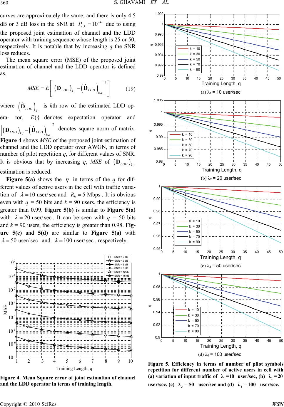 S. GHAVAMI ET AL. Copyright © 2010 SciRes. WSN 560 curves are approximately the same, and there is only 4.5 dB or 3 dB loss in the SNR at 4 ,10 ek P due to using the proposed joint estimation of channel and the LDD operator with training sequence whose length is 25 or 50, respectively. It is notable that by increasing q the SNR loss reduces. The mean square error (MSE) of the proposed joint estimation of channel and the LDD operator is defined as, 2 ,: ,: ˆ LDD LDD kk MSEE DD (19) where ,: ˆLDD k D is kth row of the estimated LDD op- era- tor, {}Edenotes expectation operator and 2 ,: ,: ˆ LDD LDD kk DD denotes square norm of matrix. Figure 4 shows MSE of the proposed joint estimation of channel and the LDD operator over AWGN, in terms of number of pilot repetition q, for different values of SNR. It is obvious that by increasing q, MSE of ,: LDD k D estimation is reduced. Figure 5(a) shows the in terms of the q for dif- ferent values of active users in the cell with traffic varia- tion of 10 user/sec and 5 Mbps b R. It is obvious even with q = 50 bits and k = 90 users, the efficiency is greater than 0.99. Figure 5(b) is similar to Figure 5(a) with 20 user/sec . It can be seen with q = 50 bits and k = 90 users, the efficiency is greater than 0.98. Fig- ure 5(c) and 5(d) are similar to Figure 5(a) with 50 user/sec and 100 user/sec , respectively. 12345678910 10 -7 10 -6 10 -5 10 -4 10 -3 10 -2 10 -1 10 0 Training Length, q MSE SNR = 0 dB SNR = 3 dB SNR = 6 dB SNR = 9 dB SNR = 12 dB SNR = 15 dB Training Length, q 1 2 3 4 5 6 7 8 9 10 MSE 10 -1 10 -2 10 -3 10 -4 10 -5 10 0 10 -6 10 -7 Figure 4. Mean Square error of joint estimation of channel and the LDD operator in terms of training length. 05 10 15 20 25 30 35 40 45 50 0. 99 0. 992 0. 994 0. 996 0. 998 1 1. 002 Training Length, q k = 10 k = 30 k = 50 k = 70 k = 90 (a) λ 1 = 10 user/sec 05 10 15 2025303540 45 50 0. 98 0. 985 0. 99 0. 995 1 1. 005 Training Length, q k = 10 k = 30 k = 50 k = 70 k = 90 (b) λ 2 = 20 user/sec 0510 15 20 25 30 35 40 45 50 0.95 0.96 0.97 0.98 0.99 1 Training Length, q k = 10 k = 30 k = 50 k = 70 k = 90 (c) λ 3 = 50 user/sec 0510 15 202530 354045 50 0. 9 0. 92 0. 94 0. 96 0. 98 1 Training Length, q k = 10 k = 30 k = 50 k = 70 k = 90 (d) λ 4 = 100 user/sec Figure 5. Efficiency in terms of number of pilot symbols repetition for different number of active users in cell with (a) variation of input traffic of 1 λ=10 user/sec, (b) 2 λ=20 user/sec, (c) 3 λ=50 user/sec and (d) 4 λ= 100 user/sec. 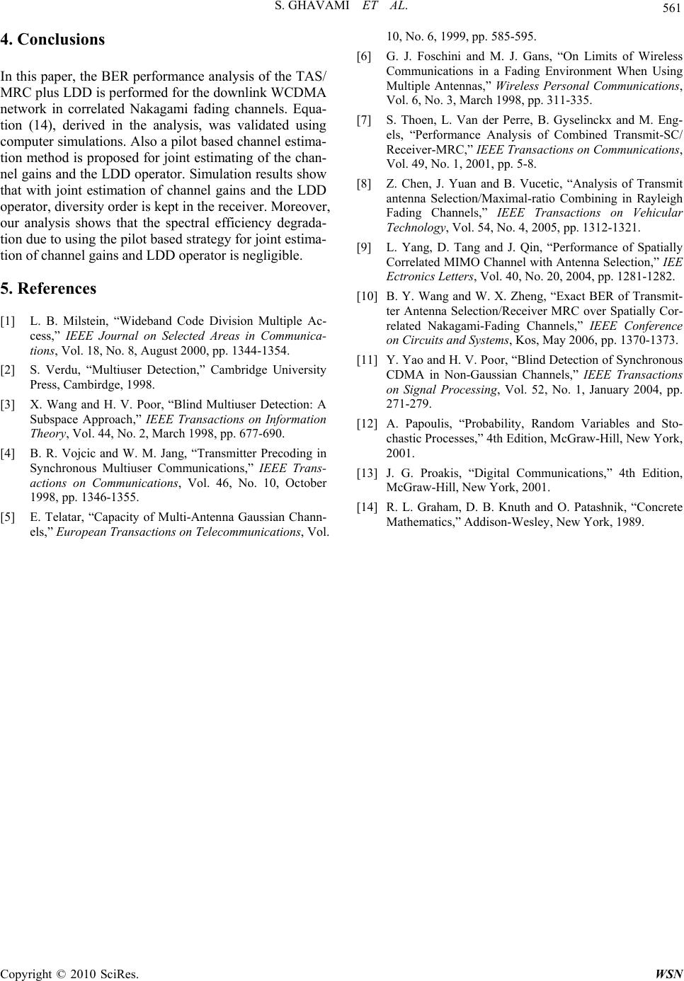 S. GHAVAMI ET AL. Copyright © 2010 SciRes. WSN 561 4. Conclusions In this paper, the BER performance analysis of the TAS/ MRC plus LDD is performed for the downlink WCDMA network in correlated Nakagami fading channels. Equa- tion (14), derived in the analysis, was validated using computer simulations. Also a pilot based channel estima- tion method is proposed for joint estimating of the chan- nel gains and the LDD operator. Simulation results show that with joint estimation of channel gains and the LDD operator, diversity order is kept in the receiver. Moreover, our analysis shows that the spectral efficiency degrada- tion due to using the pilot based strategy for joint estima- tion of channel gains and LDD operator is negligible. 5. References [1] L. B. Milstein, “Wideband Code Division Multiple Ac- cess,” IEEE Journal on Selected Areas in Communica- tions, Vol. 18, No. 8, August 2000, pp. 1344-1354. [2] S. Verdu, “Multiuser Detection,” Cambridge University Press, Cambirdge, 1998. [3] X. Wang and H. V. Poor, “Blind Multiuser Detection: A Subspace Approach,” IEEE Transactions on Information Theory, Vol. 44, No. 2, March 1998, pp. 677-690. [4] B. R. Vojcic and W. M. Jang, “Transmitter Precoding in Synchronous Multiuser Communications,” IEEE Trans- actions on Communications, Vol. 46, No. 10, October 1998, pp. 1346-1355. [5] E. Telatar, “Capacity of Multi-Antenna Gaussian Chann- els,” European Transactions on Telecommunications, Vol. 10, No. 6, 1999, pp. 585-595. [6] G. J. Foschini and M. J. Gans, “On Limits of Wireless Communications in a Fading Environment When Using Multiple Antennas,” Wireless Personal Communications, Vol. 6, No. 3, March 1998, pp. 311-335. [7] S. Thoen, L. Van der Perre, B. Gyselinckx and M. Eng- els, “Performance Analysis of Combined Transmit-SC/ Receiver-MRC,” IEEE Transactions on Communications, Vol. 49, No. 1, 2001, pp. 5-8. [8] Z. Chen, J. Yuan and B. Vucetic, “Analysis of Transmit antenna Selection/Maximal-ratio Combining in Rayleigh Fading Channels,” IEEE Transactions on Vehicular Technology, Vol. 54, No. 4, 2005, pp. 1312-1321. [9] L. Yang, D. Tang and J. Qin, “Performance of Spatially Correlated MIMO Channel with Antenna Selection,” IEE Ectronics Letters, Vol. 40, No. 20, 2004, pp. 1281-1282. [10] B. Y. Wang and W. X. Zheng, “Exact BER of Transmit- ter Antenna Selection/Receiver MRC over Spatially Cor- related Nakagami-Fading Channels,” IEEE Conference on Circuits and Systems, Kos, May 2006, pp. 1370-1373. [11] Y. Yao and H. V. Poor, “Blind Detection of Synchronous CDMA in Non-Gaussian Channels,” IEEE Transactions on Signal Processing, Vol. 52, No. 1, January 2004, pp. 271-279. [12] A. Papoulis, “Probability, Random Variables and Sto- chastic Processes,” 4th Edition, McGraw-Hill, New York, 2001. [13] J. G. Proakis, “Digital Communications,” 4th Edition, McGraw-Hill, New York, 2001. [14] R. L. Graham, D. B. Knuth and O. Patashnik, “Concrete Mathematics,” Addison-Wesley, New York, 1989. |