Green and Sustainable Chemistry, 2012, 2, 91-96
http://dx.doi.org/10.4236/gsc.2012.23014 Published Online August 2012 (http://www.SciRP.org/journal/gsc)
Production of Carbon Nanotubes and Hydrogen Catalyzed
with Ni/MCM-41 Catalysts
Zhiqi Wang1*, Juan Navarrete2
1The American School Foundation, Mexico City, Mexico
2Dirección de Investigación y Posgrado, Instituto Mexicano del Petróleo, Mexico City, Mexico
Email: *wang_extreme@hotmail.com
Received March 27, 2012; revised April 28, 2012; accepted May 21, 2012
ABSTRACT
Methane catalytic decomposition (MCD) over Ni/MCM-41 catalysts was tested in a microreactor to simultaneously
produce hydrogen and carbon nanotubes (CNTs). The methane conversion reached 30% to 47% at a moderate tempera-
ture range from 400˚C to 600˚C and the catalytic activity of the catalysts remains stable during 500 min steam on time.
CNTs were chiefly formed through tip-growth mode, due to the weak interaction between the metallic Ni and the sup-
port. Most of the Ni particles are located on the tip of the produced CNTs, which avoids rapid deactivation of the cata-
lyst resulted from carbon encapsulation. Large Ni particles usually lead to the formation of CNTs with big diameter.
During the reaction, the shape of Ni particles changed from pseudo-sphere to diamond-like. All the CNTs consist of
multiple layer walls and are curved in certain degree.
Keywords: Methane Catalytic Decomposition; Hydrogen, Carbon Nanotubes; Catalysts; Ni/MCM-41
1. Introduction
Currently, a great attention has been paid to the use of
hydrogen on a very large scale in chemicals, food and
petroleum refining industries, fuel cell technology, space
exploration and other fields. Hydrogen as a fuel has sev-
eral advantages: it is widely available, easy to handle and
has the largest heating coefficient among fuels; more
important is that, water is the sole product of hydrogen
combustion; therefore, it is an environmentally friendly
fuels [1,2].
Several techniques have been developed for hydrogen
production including: steam reforming, biomass gasifica-
tion, and water electrolysis etc. [3]. In the steam reform-
ing of hydrocarbons, one of the products, CO, has to be
removed by subsequent steps because it strongly poisons
the Pt-catalyst which is the key of fuel cell technology.
This significantly increases the production cost. Elec-
trolysis of water may offer clean hydrogen without CO;
however, it is too expensive as a result of electricity
utilization. One of the most promising routes for hydro-
gen production is the direct decomposition of methane,
which has the highest hydrogen to carbon ratio in com-
parison with other hydrocarbon compounds. Through this
approach, formation of CO can be avoided; thus, the
subsequent steps for removal of CO are not necessary.
This route is believed to be superior to both electrolysis
of water and steam reforming from the economical point
of view [3,4].
On the other hand, carbon nanotubes have also at-
tracted great attention for a long time due to their excel-
lent properties and potential utilization in a variety of
nanotechnologies [5,6]. One technique used to produce
CNTs is the catalytic growth of carbon atoms from de-
composition of hydrocarbons. In the methane catalytic
decomposition (MCD), if the production of both hydro-
gen and carbon nanotubes can be effectively combined,
we may simultaneously obtain CO-free hydrogen and
CNTs by using the same reaction.
The most commonly catalysts used for MCD are the
transition metals group VIII (Co, Ni or Fe) supported on
oxides like Al2O3 and SiO2. Rahammad and coworkers
report that the MCD reaction over a 5 wt% Ni/γ-Al2O3
showed a high activity between 500˚C and 550˚C in a
thermal balance evaluation system [7]. The catalyst ex-
hibited high activity at 500˚C in fifteen hours of reaction.
It was rapidly deactivated within 2 - 3 hrs above 600˚C
due to the deposition of carbon materials. Carbon forma-
tion was also investigated in the MDC over bare α-Fe
and with Fe/Al2O3, Fe/ZrO2, Fe/SiO2 and Fe/TiO2 cata-
lysts at temperatures between 400˚C and 600˚C [8]. Un-
der the same reaction condition, 13.5 g, 14 g, 17.4 g and
45 g carbon were yielded over the ZrO2, Al2O3, TiO2 and
SiO2 supported Fe catalysts, respectively. This work
*Corresponding author.
C
opyright © 2012 SciRes. GSC
Z. Q. WANG, J. NAVARRETE
92
clearly shows that catalyst support greatly impacts on the
catalytic activity and carbon production.
It is noteworthy that mesoporous materials like MCM-
41 and SBA-15 were frequently used as catalyst support
due to their great surface area (>800 m2/g), large pore
volume (>0.5 cm3/g) and ordered pore system [9-11]. In-
vestigating of the catalyst with new support like me-
soporous MCM-41 for simultaneous production of CO-
free hydrogen and CNTs will be an interesting research
task.
In the present work, Ni/MCM-41 catalysts was used
for simultaneous production of CO-free hydrogen and
CNTs and its catalytic activity and stability were tested
in a microreactor using methane as reaction feedstock.
Carbon nanotube formation, including its wall thickness,
length, diameter and shape was discussed.
2. Experimental
2.1. MCM-41 Synthesis
For MCM-41 synthesis, fumed silica was used as Si
source and cetyltrimethylammonium chloride (CTACl) as
synthetic template. 1.2 g of fumed silica were added into
10.0 g of 45% tetrabutylammonium hydroxide (TBAOH)
aqueous solution while vigorously stirring for 30 min to
form a transparent gel. Then, 30 g of cetyltrimethylam-
monium chloride (25 wt% solution in water) were added
into the above gel during agitation. The gel was ther-
mally aged at 80˚C for 72 h; afterwards, the mixture was
filtered and washed 3 times using 500 ml deionized water,
and the resultant solid was dried at ambient temperature
for 12 hrs. It was then calcined at 600˚C for 6 hrs under
an air flow condition (air flow rate was 60 ml/min). In
the calcination procedure, care was taken by increasing
the temperature with a rate 1˚C/min, in order to avoid
mesostructure collapsing of the sample. All the chemi-
cals used in this work were supplied by Sigma Chemical
Co. Ltd.
2.2. Preparation of Ni/MCM-41 Catalysts
The Ni/MCM-41 catalysts were prepared by impregnat-
ing MCM-41 support with Ni(NO3)2 solution. The Ni
loading of the catalysts was 10 wt%, 20 wt% and 30 wt%,
respectively. After impregnation, the Ni supported MCM-
41 samples were dried at 70˚C for 10 h and then calcined
at 600˚C for 4 h. Before the catalytic evaluation, the
catalyst samples were reduced using 99.9% H2 at 500˚C
for 2 h with a flow rate of 30 ml/min to obtain metallic
Ni particles on the catalyst.
2.3. Characterization of the Materials
The crystalline structures of the catalyst samples were
analyzed with X-ray diffraction technique in a PANa-
lytical difractometer (Model: X’Pert PRD) with a mono-
chromatic CuK
1 radiation (λ = 1.5400 Å). The evalua-
tion of the diffractograms was made by DIFFRAC/AT
software. The scanning was made from 30˚ to 100˚, with
a 2
step size of 0.01˚ and a step time of 2 s.
The Raman spectrum was obtained at room tempera-
ture using a LabRam HR 800 spectrometer, equipped
with a CCD detector. A laser diode of He-Ne system
supplies a 633 nm exciting line and spectral resolution of
4 cm–1.
Transmission electron microscopy (TEM) observa-
tions were carried out in a JEM-2200FS transmission
electron microscope with accelerating voltage of 200 kV.
The microscope was equipped with a Schottky-type field
emission gun and an ultra-high-resolution (UHR) con-
figuration (Cs = 0.5 mm; Cc = 1.1 mm; point-to-point
resolution, 0.19 nm) and an omega-type in-column en-
ergy filter. The powder samples were grounded softly in
an agate mortar and dispersed in isopropyl alcohol in an
ultrasonic bath for several minutes. A few drops were
then deposited on 200 mesh copper grids covered with a
carbon film.
2.4. Catalytic Evaluation
The MCD reaction was carried out in a microreactor
system (Advanced Scientific Design-RXM-100) with a
stainless steel fixed bed reactor (10 mm i.d. and 500 mm
in length) at atmospheric pressure. The reaction tem-
peratures varied from 400˚C to 600˚C. The catalyst load-
ing was ca. 150 mg. The inlet mixture was methane di-
luted in argon. The total inlet flow of the reaction gases
was 75 ml/min (6 ml of methane and 69 ml of Ar). The
rate of methane fed to the reactor was 2.67 mmol/min.
The temperature increasing rate was 10˚C/min. The com-
positions of the effluents were analyzed by an on-line gas
chromatograph (GC) analyzer in couple with a PE-Mol-
sieve capillary column, using a thermal conductivity de-
tector (TCD) for hydrogen analysis and a flame ioniza-
tion detector (FID) for methane analysis.
3. Results and Discussion
3.1. Structure of Ni/MCM-41 Catalysts
The crystalline structures and phases of the Ni/MCM-41
catalysts were analyzed by XRD technique. As shown in
Figure 1, several XRD peaks at 44.5˚, 51.5˚, 76.3˚ and
92.7˚ corresponding to metallic Ni in the catalysts are ob-
served. The peak becomes sharper as the Ni loading in-
creases from 10 wt% to 20 wt% and 30 wt%, indicating
that the diameter of Ni particle is larger at higher Ni
loading.
The morphological features of the Ni/MCM-41 solids
were studied by TEM. Figure 2 shows the TEM micro-
graphs of the 30% Ni/MCM-41 solid calcined at 600˚C.
Copyright © 2012 SciRes. GSC
Z. Q. WANG, J. NAVARRETE 93
406080 100
0
700
1400
2100
2800
3500
Intensity (a. u.)
2-Theta (Degrees)
a10 Ni%/MCM-41
b20Ni%/M CM-41
c30 Ni%/MCM-41
a
b
c
Figure 1. XRD patterns of the catalysts with different Ni
content.
Figure 2. A TEM micrograph of a 30% Ni/MCM-41 catalyst.
In this catalyst, many Ni particles with a shape as pseu-
do-sphere are observed. The distribution of Ni particle
size is not homogeneous, ranging from 10 nm to 50 nm
with an average diameter approximately 35 nm. Because
the Ni particles were loaded on the catalyst by using an
impregnation method, it was difficult to control the Ni
particle size distribution; however, the uneven distribu-
tion of the Ni particle size allowed us to investigate the
effect of Ni particle size on the formation of carbon na-
notubes during the reaction.
3.2. Catalytic Evaluation
Methane conversion over the Ni/MCM41catalysts is
shown in Figure 3. Over all the catalysts, methane con-
version increases with the reaction temperature increas-
ing; for example, as the reaction temperature increases
from 400˚C to 600˚C, the CH4 conversion over the 20
wt% Ni/MCM-41 catalyst enhances from approximately
30% to 42%. It is seen that 550˚C is the best reaction
temperature. Higher reaction temperature may result in
the Ni particles sintering, thus reducing the catalytic ac-
tivity. In the following experiments, we fixed the reac-
tion temperature at 550˚C.
In order to evaluate the catalytic stability of the cata-
lysts, MCD reaction was also tested in a period of 500
min at 550˚C. The results are presented in Figure 4.
These catalysts exhibit high stability in this period. The
average methane conversion is around 31% for 10%
Ni/MCM-41, 43.2% for 20% Ni/MCM-41 and 45.9% for
30% Ni/MCM-41, respectively. It is found that the
methane conversion over the 10 wt% Ni/MCM-41 cata-
lyst slightly decreases after 330 min of reaction, an ap-
proximately 7% drop is achieved. This catalyst contains
small Ni particles which can be easily encapsulated by
carbon deposits in the reaction, leading to activity de-
crease.
Figure 3. Methane conversion as a function of reaction tem-
perature.
060120 180 240 300 360 420480 540
0
10
20
30
40
50
Methane conversion (%)
Reaction time (min)
10% Ni /MCM-41
20% Ni /MCM-41
30% Ni /MCM-41
Figure 4. Methane conversion as a function of reaction time.
Copyright © 2012 SciRes. GSC
Z. Q. WANG, J. NAVARRETE
94
During the reaction, both CO and CO2 were not de-
tected. Therefore, hydrogen selectivity was 100%. In 500
min of reaction, around 827 ml, 1146 ml and 1201 ml of
hydrogen were respectively produced on the catalysts
with 10, 20 and 30 wt% of Ni. The catalyst with higher
Ni loading produces more hydrogen; this is related with
more Ni active sites in the surface of the catalyst for
methane decomposition.
3.3. Carbon Nanotube Formation
The formation of carbon nanotubes was studied by using
Raman spectroscopy and electron transmission micro-
scope. Figure 5 shows a Raman spectrum of the 30 wt%
Ni/MCM-41 catalyst after 500 min of reaction. Two bands
around 1576 cm–1 and 1325 cm–1 are observed. The peak
around 1576 cm–1 corresponds to G band of the graphitic
carbon arising from the C-C stretching vibration; the
peak around 1325 cm–1 is assigned to D band, corre-
sponding to amorphous carbon or disorder structure and
lattice defects in the microcrystalline carbon [12]. Raman
spectrum indicates that two kinds of carbon were formed
in the catalysts.
Figure 6 shows the TEM micrographs of the spent
catalysts. Many CNTs with thick (multiwall) layers are
clearly observed (Figure 6(a)). It is found that CNTs
mainly grew with a tip-growth mode in which CNTs
grow with Ni particle on its tip. This can be explained by
the interaction degree between the Ni particles and the
MCM-41 support [13]. In the present work, the Ni is
introduced onto the surface of the support by impregna-
tion, and therefore, Ni particles are mainly loaded on the
surface but are not embedded or anchored inside the
support, thus interaction between the Ni particles and the
support is weak, which is in favour of the formation of
carbon nanotube through the tip-growth mode, prevent
the Ni particles from carbon encapsulation, and thus the
Figure 5. A Raman spectrum of 30%Ni/MCM-41 spent ca-
talyst after 500 min of reaction.
(a)
(b)
(c)
Figure 6. TEM micrographs of the 30 wt% Ni/MCM-41 ca-
talyst after 500 min reaction.
Copyright © 2012 SciRes. GSC
Z. Q. WANG, J. NAVARRETE 95
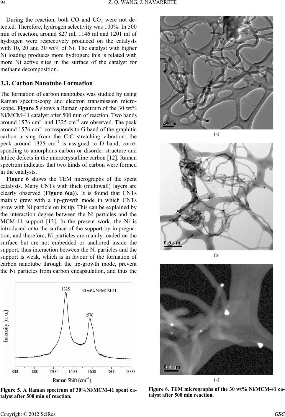
catalyst remains a long lifetime. The diameter of CNTs
has a close relation with the Ni particle size; large Ni
particles lead to formation of CNTs with big diameter
(Figure 6(b)). As a result, the inner diameter of the
CNTs is largely determined by the diameter of the Ni
particle. It is also observed that almost all of the CNTs,
no matter whether they have thin or thick tube walls, are
curved in certain degree (Figures 6(a) and (b)).
On the fresh Ni/MCM-41 catalysts, most of the Ni par-
ticles have a shape as pseudo-sphere (Figure 2). How-
ever, after the reaction, the Ni particle shows a shape
diamond-like with a tail inserting into the carbon nano-
tube (Figure 6(c)). It is known that the melting point of
metallic Ni is around 1452˚C, Ni particle may change its
shape only at a temperature above its Tamman point Tm
= 726˚C. Under the present reaction condition, the reac-
tion temperature is 550˚C. It seems impossible for Ni
particle to alter its shape. It is reported that on a spent
Ni/SiO2 catalyst, Ni carbide (Ni3C) is formed [14]. Ni3C
is unstable and it can be decomposed into nickel and
graphitic carbon at a relative low temperature, i.e., 400˚C.
It is also proven that carbon atoms produced from CH4
decomposition over the Ni based catalysts can form
NixCy solid solution as intermediate [15], at such condi-
tion, C atoms are able to move within the bulk of Ni par-
ticles and are then they are released from the NixCy solid
solution to form nanotubes at the interface of the Ni par-
ticle and support. Because methane decomposition is an
exothermic reaction (ΔH = 75 kJ/mol), the temperature
around Ni particle surface is, therefore, at somewhat
overheat state, with respect to its surrounding tempera-
ture. As a result, the Ni-C system may transfer into a
quasi-liquid state at a reaction temperature even lower
than the Tamman temperature of Ni; this provides the
possibility for Ni changing its shape. It is also noted that
a gradient of carbide concentration in the Ni particles
during the reaction leads to pressure built up at the inter-
face of Ni and support. When the graphitic layers are
initially formed in parallel to the Ni crystal surface, car-
bon nanotube growth along the Ni crystal surface may
drive the Ni particles to be squeezed out, changing Ni
shape from pseudo-sphere to diamond-like.
4. Conclusion
The present work confirms that simultaneous production
of hydrogen and CNTs can be realized in a single reac-
tion of methane catalytic decomposition by using Ni/
MCM-41 as catalyst. The Ni/MCM-41 catalysts exhibit
high catalytic stability during 500 min of reaction. The
formed CNTs have 20 - 50 nm in diameters and a few
micrometers in length, depending on the reaction condi-
tion. Large Ni particles usually favour the formation of
CNTs with big diameter. During the reaction, the shape
of Ni particles changes from pseudo-sphere to diamond-
like. All the CNTs consist of multiple layer walls and are
curved in certain degree. The CNTs formation may grow
with a tip-growth mode due to the weak interaction be-
tween Ni and MCM-41 support.
5. Acknowledgements
The authors would like to thank Mr. L. A. Moreno, Dr. J.
Alberto Andraca Adame, and Dr. C. Angeles for their tech-
nical assistance.
REFERENCES
[1] L. Barretoa, A. Makihira and K. Riahi, “The Hydrogen
Economy in the 21st Century: A Sutainable Development
Scenario,” International Journal of Hydrogen Energy,
Vol. 28, No. 3, 2003, pp. 276-284.
[2] P. Tomczyk, “Fundamental Aspects of the Hydrogen
Economy,” World Futures: The Journal of Global Edu-
cation, Vol. 65, No. 5-6, 2009, pp. 427-435.
doi:10.1080/02604020903021818
[3] J. D. Holladay, “An Overview of Hydrogen Production
Technologies,” Catalysis Today, Vol. 139, No. 4, 2009,
pp. 244-260. doi:10.1016/j.cattod.2008.08.039
[4] Y. Li, D. Li and D. Wang, “Methane Decomposition to
COx-Free Hydrogen and Nano-Carbon Materials on Group
8-10 Base Metal Catalysts: A Review,” Catalysis Today,
Vol. 162, No. 1, 2011, pp. 1-46.
doi:10.1016/j.cattod.2010.12.042
[5] K. P. De Jong and J. W. Geus “Carbon Nanofibers: Ca-
talysis Synthesis and Applications,” Catalysis Review:
Science & Technology, Vol. 42, No. 2, 2000, pp. 481-510.
[6] P. J. F. Harris, “Carbon Nanotubes and Related Structures:
New Materials for the Twenty-First Century,” Cambridge
University Press, Cambridge, 2003.
[7] M. S. Rahammad, E. Croiset and R. R. Hudgins, “Cata-
lytic Decomposition of Methane for Hydrogen Produc-
tion,” Topics in Catalysis, Vol. 37, No. 2-4, 2006, pp.
137-145. doi:10.1007/s11244-006-0015-8
[8] M. A. Ermakova, D. Y. Ermakov, A. L. Chuvilin and G.
G. Kuvshinov, “Decomposition of Methane over Iron
Catalysts at the Range of Moderate Temperatures: The
Influence of Structure of the Catalytic Systems and the
Reaction Conditions on the Yield of Carbon and Mor-
phology of Carbon Filaments,” Journal of Catalysis, Vol.
201, No. 2, 2001, pp. 183-197.
doi:10.1006/jcat.2001.3243
[9] J. S. Beck, J. C. Vartuli, W. J. Roth, M. E. Leonowics, C.
T. Kresge, K. D. Schmitt, C. T.-W. Chu, D. H. Olson, E.
W. Sheppard, S. B. McCullen, J. B. Higgins and J. L.
Schlenker, “A New Family of Mesopoous Molecular
Sieves Prepared with Liquid Crystal Template,” Journal
of the American Chemical Society, Vol. 114, No. 27,
1992, pp. 10834-10843. doi:10.1006/jcat.2001.3243
[10] A. Sayari, M. Jaroniec and T. J. Pinnavaia, “Studies in
Surface Science and Catalysis. Vol. 129: Nanoporous Ma-
terials II,” Elsevier Science, Amsterdam, 2000.
[11] H. C. Liu, H. Wang, J. H. Shen, Y. Sun and Z. M. Liu,
Copyright © 2012 SciRes. GSC
Z. Q. WANG, J. NAVARRETE
Copyright © 2012 SciRes. GSC
96
“Preparation, Characterization and Activities of Nano-
Sized Ni/SBA-15 Catalyst for Producing COx-Free Hy-
drocarbon from Ammonia,” Applied Catalysis A: General,
Vol. 337, No. 2, 2008, pp. 138-147.
[12] A. Jorio, M. A. Pimenta, A. G. Souza Pilho, R. Satio, G.
Dresselhaus and M. S. Dresselhaus, “Characterizing Car-
bon Nanotube Samples with Resonance Raman Scatter-
ing,” New Journal of Physics, Vol. 5, No. 1, 2003, p. 139.
[13] E. Laouroux, P. Serp and P. Kalck, “Catalytic Routes
toward Single Wall CNTs,” Catalysis Review: Science &
Technology, Vol. 49, No. 3, 2007, pp. 341-405.
[14] T. V. Choudhary, C. Sivadinarayana, C. C. Chusuei, A.
Klinghoffer and D. W. Goodman “Hydrogen Production
via Catalytic Decomposition of Methane,” Journal of
Catalysis, Vol. 199, No. 1, 2001, pp. 9-18.
doi:10.1006/jcat.2000.3142
[15] P. L. Hansen, S. Helveg and A. K. Dayte, “Atomic-Scale
Imaging of Supported Metals Nanocluster Catalysts in the
Working State,” Advanced Catalyst, Vol. 50, 2006, pp.
77-95. doi:10.1016/S0360-0564(06)50002-1