Journal of Crystallization Process and Technology, 2012, 2, 121-123
http://dx.doi.org/10.4236/jcpt.2012.23016 Published Online July 2012 (http://www.SciRP.org/journal/jcpt)
121
Design and Calculation for Test Tube with the Aim of
Regulation Simultaneous Crystallization Tests
Aco Janicijevic1, Nebojsa Danilovic2, Branislav Cabric2*
1Faculty of Technology and Metallurgy, University of Belgrade, Belgrade, Serbia; 2Faculty of Sciences, University of Kragujevac,
Kragujevac, Serbia.
Email: *branko.cabric@gmail.com
Received May 7th, 2012; revised June 11th, 2012; accepted June 19th, 2012
ABSTRACT
A design for an air-cooled test tube, with a series of modular and movable rings (cylindrical “crystallization comb”),
installed in a laboratory crucible furnace is presented. The setup allows easy regulation simultaneous crystallization
tests of a series of different crystallization rates in several columns (matrix) of test tubes, enabling fast studies of ob-
taining crystals. This low-budget, portable device (i.e. adjustable airstream with more simple control options), can also
be applied in tube and chamber furnaces. The relations between the crystallization rate and parameters of air-cooled test
tube are given and numerically analyzed.
Keywords: Technique for Crystal Growth; Design and Calculation; Test Tube—Cylindrical Crystallization Combs;
Crystallization Clusters—Obtaining Crystals from Melt
In a previous paper [1] we have described a design for
air-cooled test tube (bilateral “crystallization comb”),
installed in a laboratory chamber furnace with the aim of
regulating the crystallization fronts and rates in a two
columns of crucibles. In this paper, we describe the de-
velopment and improvement of the exterior of the cooler,
i.e. modular air-cooled test tube (cylindrical “crystalliza-
tion comb”) with several columns of test tubes (“crystal-
lization cluster”) (Figure 1), and a numerical study of
control options of matrix of new crystallization parame-
ters (Figures 2 and 3). The improved cooler is simpler to
build and handle, features regulation of different crystal-
lization fronts and rates in several columns of test tubes
[with the help of telescopic movable tube/sieve—see (5)
in Figure 1(a)] or rings—see (9) in Figure 1(b)]. This
stationary and adaptive device, with operating body air
(gas), allows easy regulation simultaneous crystallization
tests of different crystallization parameters and sub-
stances, enabling fast studies of obtaining single crystals
from substances with unknown crystallization parameters,
using a laboratory furnaces.
By the assumption that the liberated latent heat of so-
lidification is equal to the heat removed by the air stream
through the cooler, the following expression for the ma-
trix of crystallization rates Rij in the test tubes (see Fig-
ure 1(b)) is derived [4]:

1
j
ij
ccijjc c
T
Rkk
 
 (1)
where i and j denote the indices of internal rings and ex-
ternal rings/plugs, c is the crystallization substance index,
ΔT denotes the difference between the temperature of the
melt and that of the air stream, λ is the latent heat of so-
lidification, ρ designates the crystal density, α is the co-
efficient of heat transfer from the cooler wall to the air
stream, k designates the heat conductivity.
Figure 1. Air-cooled test tube (cylindrical “crystallization
comb”) in a crucible furnace: (1) laboratory crucible fur-
nace, (2) air-cooled test tube (cylindrical “crystallization
comb”), (3) pipe (“draining shuttle”), (4) modular and
movable rings, (5) telescopic movable tube with mounting
holes (crystallization test sieve), (6) curved Tamman test
tubes [2,3] (“crystallization tests comb”), (7) mounting
plugs, (8) test tubes (“crystallization cluster”), (9) rings with
radial mounting holes (“junction rings”), and (10) cross
section of the air-cooled test tube.
*Corresponding author.
Copyright © 2012 SciRes. JCPT
Design and Calculation for Test Tube with the Aim of Regulation Simultaneous Crystallization Tests
122
The coefficient of heat transfer from the test tube wall
to the air stream can be calculated using the following
expression (p. 152 of [5]):
0.75
0
0.25
4.130.23 100
i
i
t
w
d





(2)
where θ is average temperature of the airstream in ˚C (up
to 1000˚C), and
0
273
273
ii
ww
where wi is average velocity of the airstream next to the
ring i (0˚C, 1.013 bar) in m/s.
On the basis of the continuity and the cross section of
the airstream, the following expression for the velocity of
the airstream next to the ring i, wi, we obtain:
22
22
tp
it
ti
dd
ww
dd


(3)
where wt denotes an average velocity of the airstream in
the test tube without ring, dt and dp is the diameter of the
test tube and the pipe respectively, di is diameter of the
ring—see (10) in Figure 1(b).
(a)
(b)
Figure 2. Crystallization rate Rij as a function of the posi-
tion of the ring along the test tube, lj, and the diameter of
the ring, di, when ΔT0 = 150˚C: –wt = 0.6 m/s; –wt = 1.2
m/s, – wt = 2 m/s. (a) di = 2 cm; (b) lj = 10 cm.
Based on the fact that the heat removed from the test
tube wall is equal to the heat accepted by the air stream,
we have derived the following expression (integral equa-
tion) for the difference between the temperature of the
melt and that of the air stream ΔTj at the point lj:
0
0
4j
l
jt
tt aa
TT Td
wd c
 
l
l (4)
where ΔT0 denotes the difference between the tempera-
ture of the melt and that of the air stream at the point lj =
0, (Figure 1(b)), αt is the coefficient of heat transfer from
the test tube without ring to the air stream [Equations (2)
and (3) when di = dp], ΔTl denotes the difference between
the temperature of the melt and that of the air stream at
the point l, ρa and ca designates density and heat capacity
of the air stream, respectively.
In accordance with Equations (1)-(4), the authors ob-
tained the numerical values of crystallization rate, Rij, as
function of lj and di (Figure 2), and wt and ΔT0 (Figure 3),
(a)
(b)
Figure 3. Crystallization rate Rij as a function of the velocity
of the airstream in the test tube, wt, and difference between
the temperature of the melt and that of the air stream at the
point l = 0 – ΔT0, when lj = 10 cm: –di = 1 cm, –di = 2
cm, – di = 2.4 cm. (a) T0 = 150˚C; (b) wt = 1 m/s.
Copyright © 2012 SciRes. JCPT
Design and Calculation for Test Tube with the Aim of Regulation Simultaneous Crystallization Tests
Copyright © 2012 SciRes. JCPT
123
in the case of bismuth: Tmelt = 271˚C, λc = 52300 J/kg, ρc
= 9800 kg/m3 and kc = 7.2 W/mK. In all numerical cal-
culation is taken that: dt = 3 cm, dp = 1 cm, δj = 0.5 cm, kj
= 0.756 W/mK (pyrex i.e. borosilicate glass, softening
point 600˚C), δc = 0 cm (Figure 1(b)), ρa = 0.682
kg/m3 and ca = 1.035 kJ/kgK.
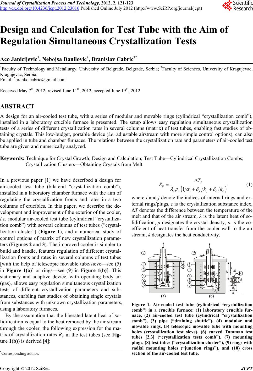
The shape of crystallization front in each test tube can
be regulated by the plug or ring front (Figure 1). The
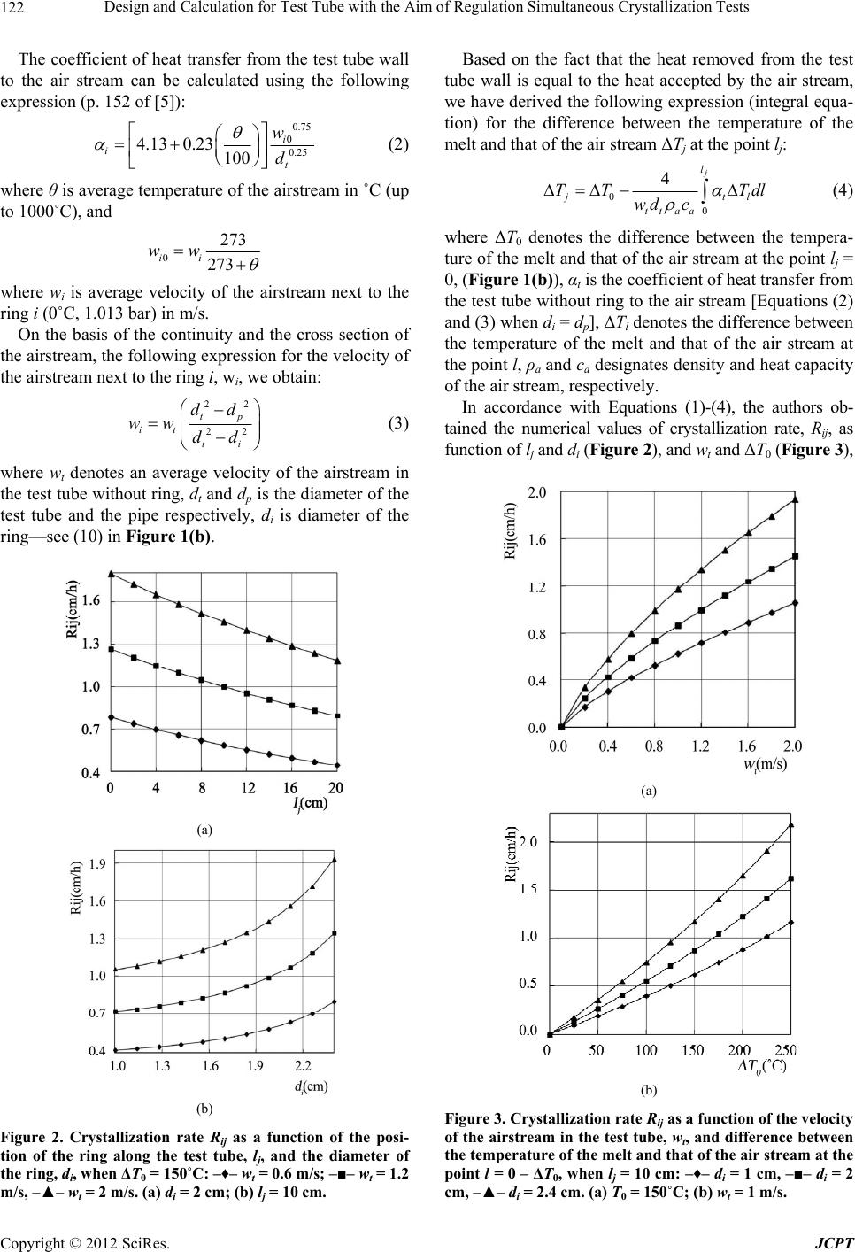
crystallization rate in each test tube can be regulated by
the position of the ring along the test tube (Figure 2(a))
and by the diameter of the ring (Figure 2(b)); and/or by
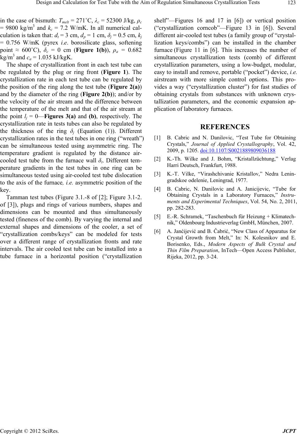
the velocity of the air stream and the difference between
the temperature of the melt and that of the air stream at
the point lj = 0—Figures 3(a) and (b), respectively. The
crystallization rate in tests tubes can also be regulated by
the thickness of the ring δj (Equation (1)). Different
crystallization rates in the test tubes in one ring (“wreath”)
can be simultaneous tested using asymmetric ring. The
temperature gradient is regulated by the distance air-
cooled test tube from the furnace wall δt. Different tem-
perature gradients in the test tubes in one ring can be
simultaneous tested using air-cooled test tube dislocation
to the axis of the furnace, i.e. asymmetric position of the
key.
Tamman test tubes (Figure 3.1.-8 of [2]; Figure 3.1-2.
of [3]), plugs and rings of various numbers, shapes and
dimensions can be mounted and thus simultaneously
tested (fineness of the comb). By varying the internal and
external shapes and dimensions of the cooler, a set of
“crystallization combs/keys” can be modeled for tests
over a different range of crystallization fronts and rate
intervals. The air cooled test tube can be installed into a
tube furnace in a horizontal position (“crystallization
shelf”—Figures 16 and 17 in [6]) or vertical position
(“crystallization corncob”—Figure 13 in [6]). Several
different air-cooled test tubes (a family group of “crystal-
lization keys/combs”) can be installed in the chamber
furnace (Figure 11 in [6]. This increases the number of
simultaneous crystallization tests (comb) of different
crystallization parameters, using a low-budget, modular,
easy to install and remove, portable (“pocket”) device, i.e.
airstream with more simple control options. This pro-
vides a way (“crystallization cluster”) for fast studies of
obtaining crystals from substances with unknown crys-
tallization parameters, and the economic expansion ap-
plication of laboratory furnaces.
REFERENCES
[1] B. Cabric and N. Danilovic, “Test Tube for Obtaining
Crystals,” Journal of Applied Crystallography, Vol. 42,
2009, p. 1205. doi:10.1107/S0021889809036188
[2] K.-Th. Wilke and J. Bohm, “Kristallzüchtung,” Verlag
Harri Deutsch, Frankfurt, 1988.
[3] K.-T. Vilke, “Virashchivanie Kristallov,” Nedra Lenin-
gradskoe odelenie, Leningrad, 1977.
[4] B. Cabric, N. Danilovic and A. Janicijevic, “Tube for
Obtaining Crystals in a Laboratory Furnaces,” Instru-
ments and Experimental Techniques, Vol. 54, No. 2, 2011,
pp. 282-283.
[5] E.-R. Schramek, “Taschenbuch für Heizung + Klimatech-
nik,” Oldenbourg Industrieverlag GmbH, München, 2007.
[6] A. Janćijević and B. Čabrić, “New Class of Apparatus for
Crystal Growth from Melt,” In: N. Kolesnikov and E.
Borisenko, Eds., Modern Aspects of Bulk Crystal and
Thin Film Preparation, InTech—Open Access Publisher,
Rijeka, 2012, pp. 3-24.