S. S. HAVALDAR ET AL.
654
load in thickness (T) direction and shear load in longitu-
dinal (L) and width (W) directions. The material proper-
ties such as elastic moduli and strengths are various in
different directions, and even the compressive and tensile
properties are different in the thickness-direction, pri-
marily due to the initial deflection of cell walls. Vibra-
tion frequencies and mode shapes of honeycomb sand-
wich panels with various structural parameters were
studied by Qunli Liu and Yi Zhao [11] using computa-
tional and experimental methods. Two computational
models were used to predict the mode shapes and fre-
quencies of honeycomb sandwich panels. Plate elements
were used for honeycomb cell walls to reflect the geo-
metric nature of the hexagonal cells. The quantitative
effect of the anisotropic core on the vibration properties
of the sandwich panels were studied and presented.
Most studies in the literature are related to one of the
attributes (high strength/weight or increased energy ab-
sorption) mentioned above. With regard to the develop-
ment of a honeycomb panels, one issue that has been
overlooked is the scaling of honeycomb properties with
respect to cell size. The variation in cell size may have a
large influence on the dynamic properties of honeycomb
panels. The current paper expands upon this study. The
results from the experimental program will be presented
and discussed. The theoretical literature available [12] on
sandwich panels in evaluating fundamental frequency
with a non-dimensional parameter will also be discussed
in this work. Of interest in this study is to understand the
effect of cell size on the fundamental frequency of hon-
eycomb panels.
2. Experimental Techniques
2.1. Fabrication of Honeycomb Panels
FRP honeycomb sandwich panels have been fabricated
through vacuum bag molding technique, which uses the
vacuum to eliminate the entrapped air and excess resin.
The adhesive used is epoxy resin LY 556 mixed with
hardener HY 951. The resin and hardener is mixed in the
weight ratio of 10:1. To maintain optimum strength of
the matrix, the ideal resin to glass ratio is found to be
35:65. The mold used is a “hexagonally machined split
molding tool” made of chromium plated mild steel. After
ensuring the surface is clean and free from foreign parti-
cles, a coat of release agent is applied. A coat of resin
mixture is then applied on the molding surface and the
plain weave glass “E” fabric is impregnated against the
first half of molding tool surface, by ensuring thorough
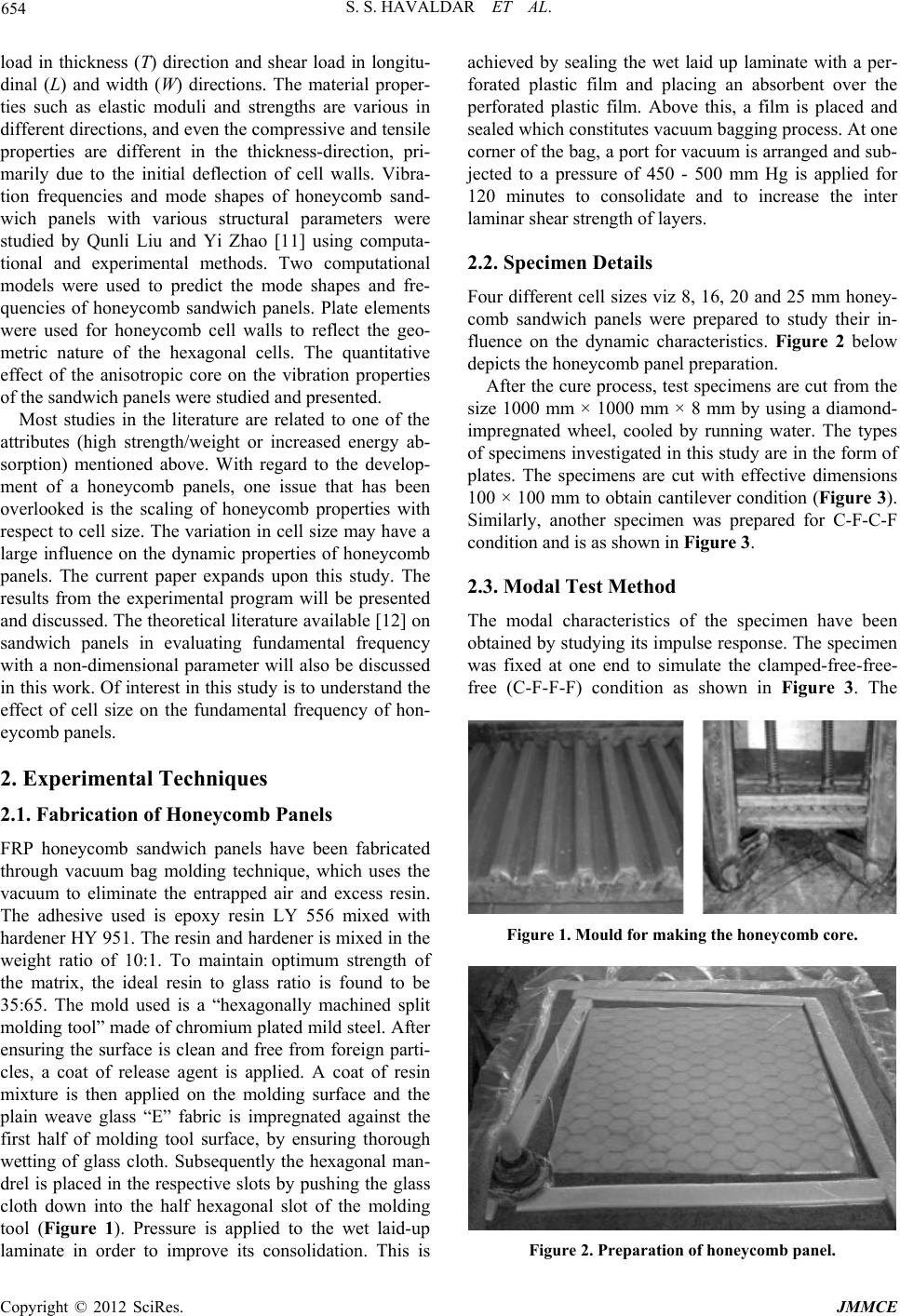
wetting of glass cloth. Subsequently the hexagonal man-
drel is placed in the respective slots by pushing the glass
cloth down into the half hexagonal slot of the molding
tool (Figure 1). Pressure is applied to the wet laid-up
laminate in order to improve its consolidation. This is
achieved by sealing the wet laid up laminate with a per-
forated plastic film and placing an absorbent over the
perforated plastic film. Above this, a film is placed and
sealed which constitutes vacuum bagging process. At one
corner of the bag, a port for vacuum is arranged and sub-
jected to a pressure of 450 - 500 mm Hg is applied for
120 minutes to consolidate and to increase the inter
laminar shear strength of layers.
2.2. Specimen Details
Four different cell sizes viz 8, 16, 20 and 25 mm honey-
comb sandwich panels were prepared to study their in-
fluence on the dynamic characteristics. Figure 2 below
depicts the honeycomb panel preparation.
After the cure process, test specimens are cut from the
size 1000 mm × 1000 mm × 8 mm by using a diamond-
impregnated wheel, cooled by running water. The types
of specimens investigated in this study are in the form of
plates. The specimens are cut with effective dimensions
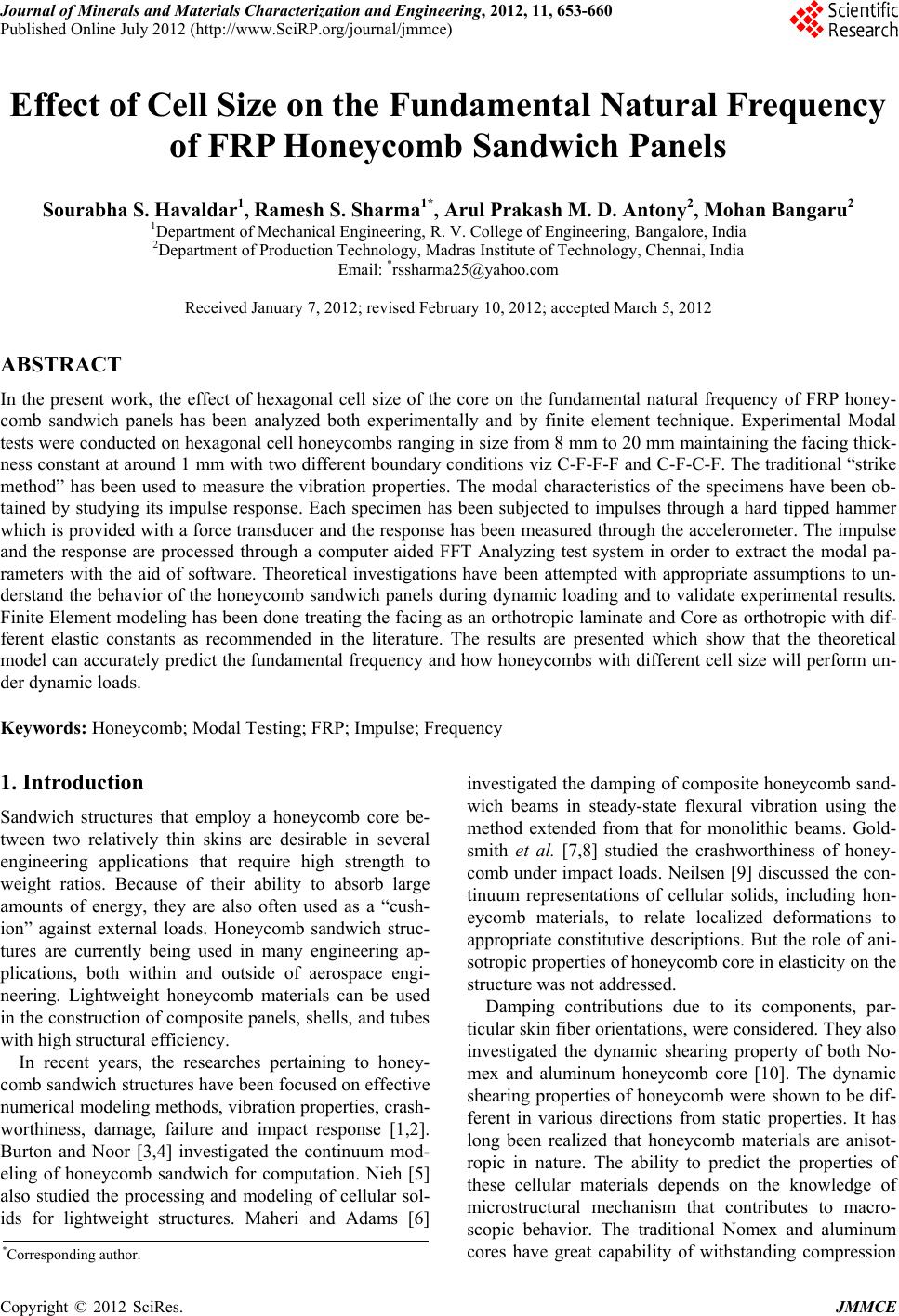
100 × 100 mm to obtain cantilever condition (Figure 3).
Similarly, another specimen was prepared for C-F-C-F
condition and is as shown in Figure 3.
2.3. Modal Test Method
The modal characteristics of the specimen have been
obtained by studying its impulse response. The specimen
was fixed at one end to simulate the clamped-free-free-
free (C-F-F-F) condition as shown in Figure 3. The
Figure 1. Mould for making the honeycomb core.
Figure 2. Preparation of honeycomb panel.
Copyright © 2012 SciRes. JMMCE