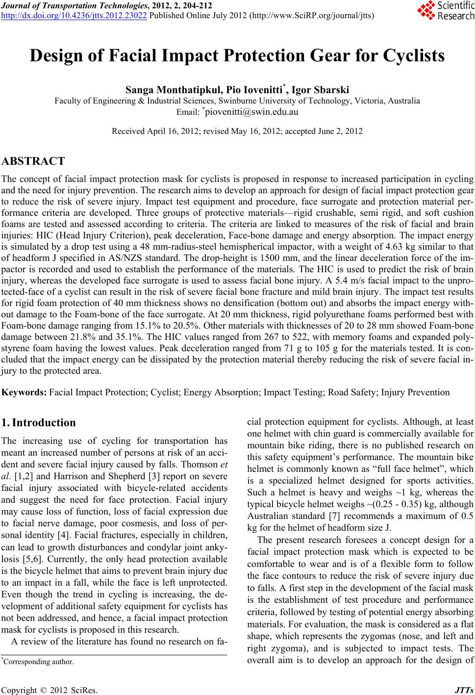
 Journal of Transportation Technologies, 2012, 2, 204-212 http://dx.doi.org/10.4236/jtts.2012.23022 Published Online July 2012 (http://www.SciRP.org/journal/jtts) Design of Facial Impact Protection Gear for Cyclists Sanga Monthatipkul, Pio Iovenitti*, Igor Sbarski Faculty of Engineering & Industrial Sciences, Swinburne University of Technology, Victoria, Australia Email: *piovenitti@swin.edu.au Received April 16, 2012; revised May 16, 2012; accepted June 2, 2012 ABSTRACT The concept of facial impact protection mask for cyclists is proposed in response to increased participation in cycling and the need for injury prevention. The research aims to develop an approach for design of facial impact protection gear to reduce the risk of severe injury. Impact test equipment and procedure, face surrogate and protection material per- formance criteria are developed. Three groups of protective materials—rigid crushable, semi rigid, and soft cushion foams are tested and assessed according to criteria. The criteria are linked to measures of the risk of facial and brain injuries: HIC (Head Injury Criterion), peak deceleration, Face-bone damage and energy absorption. The impact energy is simulated by a drop test using a 48 mm-radius-steel hemispherical impactor, with a weight of 4.63 kg similar to that of headform J specified in AS/NZS standard. The drop-height is 1500 mm, and the linear deceleration force of the im- pactor is recorded and used to establish the performance of the materials. The HIC is used to predict the risk of brain injury, whereas the developed face surrogate is used to assess facial bone injury. A 5.4 m/s facial impact to the unpro- tected-face of a cyclist can result in the risk of severe facial bone fracture and mild brain injury. The impact test results for rigid foam protection of 40 mm thickness shows no densification (bottom out) and absorbs the impact energy with- out damage to the Foam-bone of the face surrogate. At 20 mm thickness, rigid polyurethane foams performed best with Foam-bone damage ranging from 15.1% to 20.5%. Other materials with thicknesses of 20 to 28 mm showed Foam-bone damage between 21.8% and 35.1%. The HIC values ranged from 267 to 522, with memory foams and expanded poly- styrene foam having the lowest values. Peak deceleration ranged from 71 g to 105 g for the materials tested. It is con- cluded that the impact energy can be dissipated by the protection material thereby reducing the risk of severe facial in- jury to the protected area. Keywords: Facial Impact Protection; Cyclist; Energy Absorption; Impact Testing; Road Safety; Injury Prevention 1. Introduction The increasing use of cycling for transportation has meant an increased number of persons at risk of an acci- dent and severe facial injury caused by falls. Thomson et al. [1,2] and Harrison and Shepherd [3] report on severe facial injury associated with bicycle-related accidents and suggest the need for face protection. Facial injury may cause loss of function, loss of facial expression due to facial nerve damage, poor cosmesis, and loss of per- sonal identity [4]. Facial fractures, especially in children, can lead to growth disturbances and condylar joint anky- losis [5,6]. Currently, the only head protection available is the bicycle helmet that aims to prevent brain injury due to an impact in a fall, while the face is left unprotected. Even though the trend in cycling is increasing, the de- velopment of additional safety equipment for cyclists has not been addressed, and hence, a facial impact protection mask for cyclists is proposed in this research. A review of the literature has found no research on fa- cial protection equipment for cyclists. Although, at least one helmet with chin guard is commercially available for mountain bike riding, there is no published research on this safety equipment’s performance. The mountain bike helmet is commonly known as “full face helmet”, which is a specialized helmet designed for sports activities. Such a helmet is heavy and weighs ~1 kg, whereas the typical bicycle helmet weighs ~(0.25 - 0.35) kg, although Australian standard [7] recommends a maximum of 0.5 kg for the helmet of headform size J. The present research foresees a concept design for a facial impact protection mask which is expected to be comfortable to wear and is of a flexible form to follow the face contours to reduce the risk of severe injury due to falls. A first step in the development of the facial mask is the establishment of test procedure and performance criteria, followed by testing of potential energy absorbing materials. For evaluation, the mask is considered as a flat shape, which represents the zygomas (nose, and left and right zygoma), and is subjected to impact tests. The overall aim is to develop an approach for the design of *Corresponding author. C opyright © 2012 SciRes. JTTs 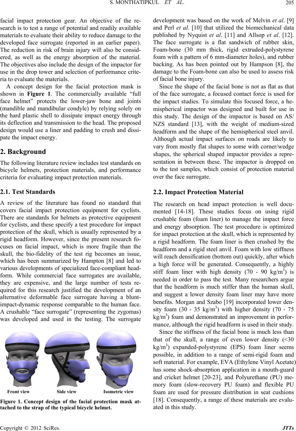 S. MONTHATIPKUL ET AL. 205 facial impact protection gear. An objective of the re- search is to test a range of potential and readily available materials to evaluate their ability to reduce damage to the developed face surrogate (reported in an earlier paper). The reduction in risk of brain injury will also be consid- ered, as well as the energy absorption of the material. The objectives also include the design of the impactor for use in the drop tower and selection of performance crite- ria to evaluate the materials. A concept design for the facial protection mask is shown in Figure 1. The commercially available “full face helmet” protects the lower-jaw bone and joints (mandible and mandibular condyle) by relying solely on the hard plastic shell to dissipate impact energy through its deflection and transmission to the head. The proposed design would use a liner and padding to crush and dissi- pate the impact energy. 2. Background The following literature review includes test standards on bicycle helmets, protection materials, and performance criteria for evaluating impact protection materials. 2.1. Test Standards A review of the literature has found no standard that covers facial impact protection equipment for cyclists. There are standards for helmets as protective equipment for cyclists, and these specify a test procedure for impact protection of the skull, which is usually represented by a rigid headform. However, since the present research fo- cuses on facial impact, which is more fragile than the skull, the bio-fidelity of the test rig becomes an issue, which has been summarized by Hampton [8] and led to various developments of specialized face-compliant head- form. While commercial face surrogates are available, they are expensive, and the large number of tests re- quired for this research justified the development of an alternative deformable face surrogate having a blunt- impact-dynamic response comparable to the human face. A crushable “face surrogate” (representing the zygomas) was developed and used in the testing. The surrogate Front view Side view Isometric view Figure 1. Concept design of the facial protection mask at- tached to the strap of the typi cal bi cycle helmet. development was based on the work of Melvin et al. [9] and Perl et al. [10] that utilized the biomechanical data published by Nyquist et al. [11] and Allsop et al. [12]. The face surrogate is a flat sandwich of rubber skin, Foam-bone (30 mm thick, rigid extruded-polystyrene foam with a pattern of 6 mm-diameter holes), and rubber backing. As has been pointed out by Hampson [8], the damage to the Foam-bone can also be used to assess risk of facial bone injury. Since the shape of the facial bone is not as flat as that of the face surrogate, a focused contact force is used for the impact studies. To simulate this focused force, a he- mispherical impactor was designed and built for use in this study. The design of the impactor is based on AS/ NZS standard [13], with the weight of medium-sized headform and the shape of the hemispherical steel anvil. Although actual impact surfaces on roads are likely to vary from mostly flat shapes to some with corner/wedge shapes, the spherical shaped impactor provides a repre- sentation in between these. The impactor is dropped on to the test samples, which consist of protection material over the face surrogate. 2.2. Impact Protection Material The research on head impact protection is well docu- mented [14-18]. These studies focus on using rigid crushable foam (foam liner) to manage the impact force and energy absorption. The test procedure is optimized for impact protection at the skull, which is represented by a rigid headform. The foam liner is then crushed by the headform and a rigid steel anvil. Foam with low stiffness will reach densification (bottom out) quickly, after which a high force will be generated. Consequently, a highly stiff foam liner with high density (70 - 90 kg/m3) is needed in order to pass the test. Many researchers argue that the headform is much stiffer than the human skull, and suggest a lower density foam liner may have more benefits. Morgan and Szabo [19] incorporated lower den- sity foam (30 - 35 kg/m3) with higher density (70 - 75 kg/m3) foam and demonstrated an improvement in perfor- mance, although the rigid headform is used in their study. Since the stiffness of the facial bone is much less than that of the skull, a range of even lower density (<30 kg/m3) expanded-polystyrene (EPS) foam liner seems possible, in addition to a range of semi-rigid foam and soft material. For example, EVA (Ethylene Vinyl Acetate) has some shock-absorption application in a mouth-guard and cricket helmet [20-23], and Polyurethane (PU) me- mory foam (slow-recovery PU foam) and flexible PU foam are used for pressure distribution in seat cushions [18]. Consequently, a range of these materials are evalu- ated in this study. Copyright © 2012 SciRes. JTTs  S. MONTHATIPKUL ET AL. 206 2.3. Performance Criteria The evaluation of performance involves a number of criteria relating to head injury and impact energy absorp- tion of the protection material. In this study, the primary measure is the risk of brain injury as a result of blunt impact on the face. The secondary measure is the risk of facial injury. The last measure is the energy absorption capability of the protective material. The following sec- tions present the literature review related to the three criteria. 2.3.1. Brain Injury Risk Assessment In many countries, mandatory bicycle helmet wearing has been enacted, along with the requirement for the helmet to pass the impact testing specified in the stan- dards, which aim to assess the risk of brain injury by measuring the level of linear deceleration of the head during the impact. A higher deceleration level typically causes higher risk of brain injury. Most standards impose a pass/fail criteria, for example, AS/NZS standard [7,13] requires 1500-mm-drop height of a rigid headform (2.5 - 6.1 kg) fastened with the helmet to be tested. To pass the test, the helmet crushing must not generate peak lin- ear-deceleration force (Gpeak) greater than 250 g, and the cumulative impact duration must not exceed 3 ms (for Gpeak > 200 g) or 6 ms (for Gpeak > 150 g). The inclusion of impact duration makes it difficult to compare perfor- mance between different protective materials, thus, the HIC (Head Injury Criterion) is used in this study. HIC was introduced in 1972 by NHTSA (National Highway Traffic Safety Administration) in the USA [24] and has been widely used as a criterion to judge the risk of head and brain injury involving blunt impact on the head. McLean et al. [25] presented a summary of a cri- tique and development of HIC, which links to the Wayne State Tolerance Curve (WSTC) that represents the rela- tionship between acceleration, pulse duration, and in- tracranial pressure. It purports to describe the limit to cerebral concussion. Similar work was performed by the Japan Automobile Research Institute that developed a JARI Human Head Tolerance Curve based on impact studies on monkey skulls, and with a conversion scale to apply to the human head. HIC incorporates impact duration in its definition (Equation (1)) and gives single a value that can be used to compare performance between protective materials. 2 12 1 2.5 21 21 1 max d , t tt t HICttG tt tt (1) G(t) pulse of deceleration (in unit of g) as a function of time; t time in unit of second (s); t2, t1 selected time under deceleration pulse that gave maximum HIC; t2 – t1 selected pulse duration with limit of 3 ms ≤ t2 – t1 ≤ 15 ms. In order to obtain the HIC value of an impact event, the Deceleration-Time history (deceleration in units of g vs. time) of the head is applied as G(t) in Equation (1). Head impact on different materials will usually have dif- ferent HIC values. Higher value means a higher risk in severe brain injury as predicted in Table 1 [26]. Head impact that produces a higher HIC value than the limit is generally not acceptable. The typical HIC limit ranges from 700 to 1000, depending on the application. 2.3.2. Fa c ial Inju ry Risk Assessment Research on skin penetration and laceration assessment can be found in forensic sciences and safety in the glass industry. However, these studies focus on ballistic impact and laceration caused by impact of a sharp object, as op- posed to blunt-impact associated with the testing in this study. As a result, the facial skin injury cannot be as- sessed in this study. The data on facial bone tolerance are available [8,27,28], which are summarized in Table 2. In this study, the face surrogate lacks a pressure sensi- tive device, and hence, pressure cannot be measured. Moreover, the peak force and peak deceleration can only be used if there is no damage to the Foam-bone, i.e., all impact energy is dissipated in the protection material. As Table 1. HIC value and predicted injury [26]. HIC Injury 135 - 519 Headache or dizziness, mild concussion 520 - 899 Unconscious < 1 hour, mild to severe concussion 900 - 1254 Unconscious 1 - 6 hours, severe concussion 1255 - 1574 Unconscious 6 - 24 hours, severe concussion 1575 - 1859 Unconscious > 25 hours, large haematoma >1860 Non survival Table 2. Facial bone tolerance to impact force, peak pres- sure and peak deceleration. Tolerance Facial bone Peak force (N) [8] Peak pressure (N/mm2) [8] Peak deceleration (g) [27,28] Nasal bone 342 - 4500.13 - 0.34 30 Zygoma 489 - 24011.38 - 4.17 50 Zygomatic arch890 - 17791.38 - 2.76 - Maxilla 668 - 18011.03 - 2.07 100 Mandible 685 - 17792.76 - 6.20 100 Mandibular angle - - 70 Orbital rim - - 200 Copyright © 2012 SciRes. JTTs  S. MONTHATIPKUL ET AL. 207 a consequence, this study requires an additional parame- ter to assess the facial injury. The Foam-bone damage will be defined as the ratio between the Foam-bone crushing distance and the Foam-bone’s original thickness. A lower value of Foam-bone damage is preferred as long as the HIC is below the limit. 2.3.3. Energy Absorption The energy absorption (Eab) capability of the protective material is also an important parameter in head protec- tion. A material with a high Eab returns little energy to the head, and hence, the head has a lower rebound veloc- ity. Thus, the risk of severe secondary impact is reduced. McLean et al. [25] explain the preferred padding charac- teristics of energy absorbing material by analyzing the shape of Force-displacement curve, which is adapted for Eab analysis in this study. A material with a high Eab is desirable; however, no specific value of Eab as a criterion has been established. 3. Methodology The following section outlines the impact test procedure and parameters, the experimental equipment and instru- mentation, the materials tested, and the evaluation crite- ria: HIC limit, Foam-bone damage, and energy absorp- tion. 3.1. Impact Energy The impact energy was provided by dropping a steel hemispherical impactor (radius 48 mm) in a drop tower shown in Figure 2. The mass of the impactor was 4.63 kg, which was approximately the same as that of head- form J specified in AS/NZS standard [13]. The drop height was 1500 mm, the impact energy was 68 Joules (J) and the calculated impact velocity (Vi) was 5.4 m/s. 3.2. Data Acquisition System A charge type accelerometer (B & K 4371) and an am- plifier (B & K Type 2635) were used to generate the ac- celeration signal, which was digitized by a digital oscil- loscope (oscill_1, Tektronix TDS 2024) at the sampling rate of 50 kHz. The impact velocity (Vi) was measured by two LED detectors spaced 100 mm apart, and the time was recorded by another oscilloscope (oscill_2, Tek- tronix TDS 210). Video of the impact event of test sub- ject with a distance scale was recorded using a high- speed digital camera (Photron APX RS) at 3000 frames/ second with shutter speed of 1/15,000 second. All data were then transferred to a personal computer for further analysis of the test results. Figure 2 shows the data ac- quisition system installed on the drop tower. Equipment calibration was done by comparing dis- placement (double integral of acceleration) from accel- erometer data with that of the high-speed video. Both results compared well especially during the loading phase. By using video data as reference, results from different impact velocities gave the average maximum error ~2% during the loading phase, and ~6% during the unloading phase. 3.3. Test Samples The test samples were categorized into three groups— rigid crushable, semi rigid, and soft cushion materials. All materials were cut to size of 150 mm × 150 mm, and the thickness ranged from 20 to 40 mm. Table 3 lists all candidate materials, as well as the face surrogate ma- terials. 3.4. Test Procedure A sample of the protective material on the face surrogate (Figure 3) is placed in the drop tower, and the impactor is dropped on the sample from a height of 1500 mm. This procedure simulates an impact on the protected face. The impact velocity and deceleration (g) versus time are re- corded, and damage to the materials is observed. In some instances a high speed camera video recording of the impact was performed for verification of displacement and time. In addition, testing on the face surrogate with- out protection is performed in order to establish a refer- ence. Tests were repeated 2 to 3 times with a new face- bone each time. The number of samples tested was lim- ited because of the long time required to produce the face-bone samples. Figure 2. Drop tower and data acquisition system. Copyright © 2012 SciRes. JTTs 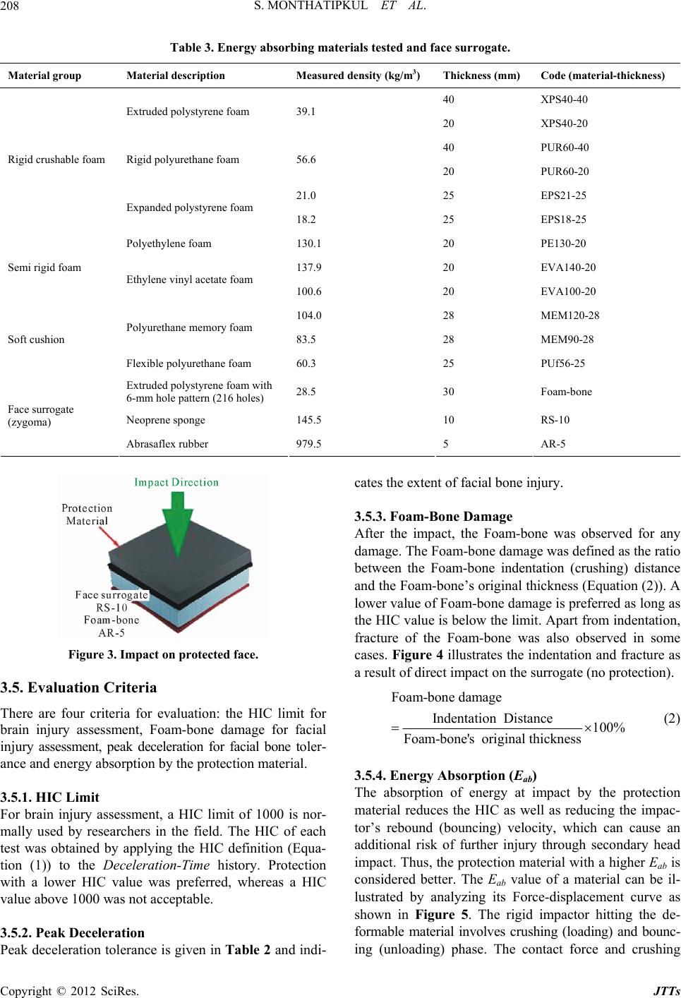 S. MONTHATIPKUL ET AL. Copyright © 2012 SciRes. JTTs 208 Table 3. Energy absorbing materials tested and face surrogate. Material group Material description Measured density (kg/m3) Thickness (mm) Code (material-thickness) 40 XPS40-40 Extruded polystyrene foam 39.1 20 XPS40-20 40 PUR60-40 Rigid polyurethane foam 56.6 20 PUR60-20 21.0 25 EPS21-25 Rigid crushable foam Expanded polystyrene foam 18.2 25 EPS18-25 Polyethylene foam 130.1 20 PE130-20 137.9 20 EVA140-20 Semi rigid foam Ethylene vinyl acetate foam 100.6 20 EVA100-20 104.0 28 MEM120-28 Polyurethane memory foam 83.5 28 MEM90-28 Soft cushion Flexible polyurethane foam 60.3 25 PUf56-25 Extruded polystyrene foam with 6-mm hole pattern (216 holes) 28.5 30 Foam-bone Neoprene sponge 145.5 10 RS-10 Face surrogate (zygoma) Abrasaflex rubber 979.5 5 AR-5 Figure 3. Impact on protected face. 3.5. Evaluation Criteria There are four criteria for evaluation: the HIC limit for brain injury assessment, Foam-bone damage for facial injury assessment, peak deceleration for facial bone toler- ance and energy absorption by the protection material. 3.5.1. HIC Limit For brain injury assessment, a HIC limit of 1000 is nor- mally used by researchers in the field. The HIC of each test was obtained by applying the HIC definition (Equa- tion (1)) to the Deceleration-Time history. Protection with a lower HIC value was preferred, whereas a HIC value above 1000 was not acceptable. 3.5.2. Pe ak Deceleration Peak deceleration tolerance is given in Table 2 and indi- cates the extent of facial bone injury. 3.5.3. Foam-Bone Damage After the impact, the Foam-bone was observed for any damage. The Foam-bone damage was defined as the ratio between the Foam-bone indentation (crushing) distance and the Foam-bone’s original thickness (Equation (2)). A lower value of Foam-bone damage is preferred as long as the HIC value is below the limit. Apart from indentation, fracture of the Foam-bone was also observed in some cases. Figure 4 illustrates the indentation and fracture as a result of direct impact on the surrogate (no protection). Foam-bone damage Indentation Distance100% Foam-bone's original thickness (2) 3.5.4. Energy Absorption (Eab) The absorption of energy at impact by the protection material reduces the HIC as well as reducing the impac- tor’s rebound (bouncing) velocity, which can cause an additional risk of further injury through secondary head impact. Thus, the protection material with a higher Eab is considered better. The Eab value of a material can be il- lustrated by analyzing its Force-displacement curve as shown in Figure 5. The rigid impactor hitting the de- formable material involves crushing (loading) and bounc- ing (unloading) phase. The contact force and crushing  S. MONTHATIPKUL ET AL. 209 Figure 4. Illustration of Foam-bone damage. Figure 5. Energy from Force-displacement curve. distance are represented by Loading curve A, whereas that of bouncing is represented by Unloading curve B. The energy of the impactor is the product of force by displacement, thus, the area under these curves represents the loading and unloading energy phase. If energy loss is negligible, the area under the Loading curve A represents the input energy (Energyinput), which is the same as the kinetic energy at the start of impact. The area under the Unloading curve B represents the energy returning (Energyreturn) to the impactor. The energy dissipated dur- ing the impact event (Energydissipated) is Energyinput minus Energyreturn, and is shown in the loop area of the Force-displacement curve. The Eab value is then calcu- lated by Equation (3). dissipated input Energy 10 0% Energy ab E (3) If the Foam-bone is not damaged, then the energy ab- sorption is attributed wholly to crushing of the protection material. If both the protection material and Foam-bone are damaged, then energy absorption is shared between the Foam-bone and the protection material. 4. Test Results and Discussion 4.1. Results of Impact on Protected Face The test results are listed in Table 4. These results are used to evaluate the performance of the protection mate- rials at an impact speed (Vi) of 5.4 m/s (achieved through a drop height 1500 mm) by impact testing on the pro- tected face surrogate. The result of the unprotected face is also provided as reference. HIC, peak deceleration, energy absorption, and damage to the materials and face surrogate are also reported. Figure 6 shows the sample of the worst Foam-bone damage. 4.2. Risk of Brain Injury Results The best materials are 40 mm-thick PUR60 and XPS40 Table 4. Impact test results on the protec ted fac e and reference unprote cted face. Material group Protection material HIC Peak deceleration Gpeak (g) Foam-bone damage (%)Eab (%)Foam-bone visible damageProtection material visible damage XPS40-40 522 105 0.0 78.3None Dented at top, bottom intact XPS40-20 461 96 15.1 78.8Dented Crushed, but no visible break PUR60-40 276 74 0.0 88.4None Radial break, crushed at centre PUR60-20 365 83 20.5 85.7Radial break, badly crushed centre EPS21-25 267 71 24.0 83.0 Rigid EPS18-25 280 71 27.6 81.7 Crushed, circular break at centre PE130-20 337 83 21.8 88.2 EVA140-20 399 89 25.1 80.2Semi rigid EVA100-20 378 86 30.9 76.1 MEM120-28 284 76 33.2 90.5 MEM90-28 306 81 33.4 82.3Soft cushion PUf56-25 363 86 35.1 83.0 Dented Crushed, slow recovery, no damage Foam-bone (no protection) - 453 112 48.7 85.1Dented, fractured- Copyright © 2012 SciRes. JTTs 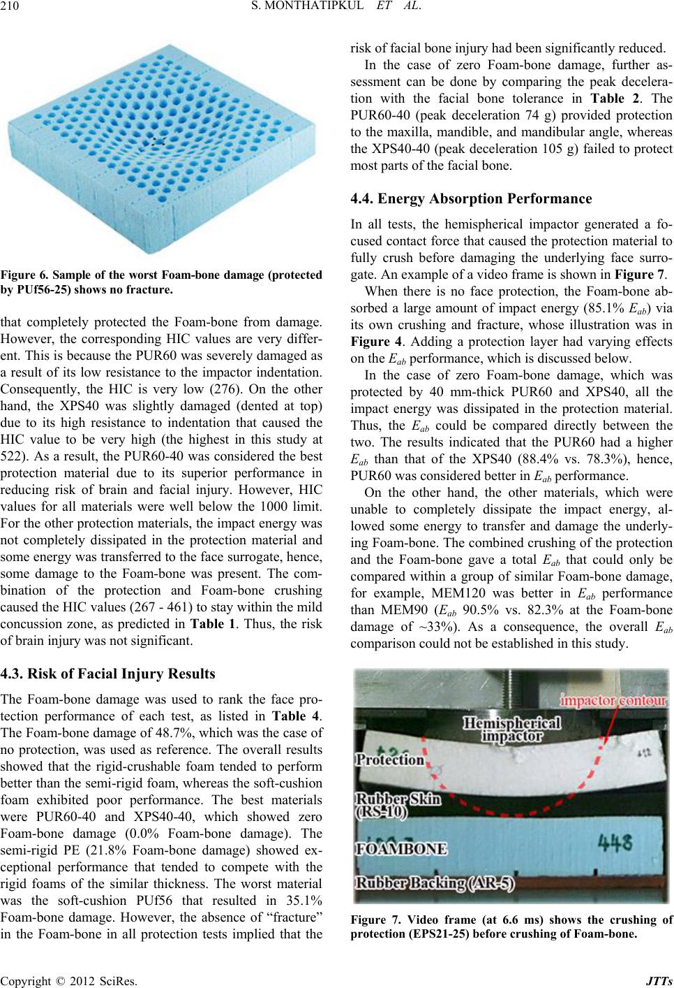 S. MONTHATIPKUL ET AL. 210 Figure 6. Sample of the worst Foam-bone damage (protecte -bone from damage. the face pro- risk of facial bone injury had been significantly reduced. nerated a fo- n material to d by PUf56-25) shows no fracture. at completely protected the Foamth However, the corresponding HIC values are very differ- ent. This is because the PUR60 was severely damaged as a result of its low resistance to the impactor indentation. Consequently, the HIC is very low (276). On the other hand, the XPS40 was slightly damaged (dented at top) due to its high resistance to indentation that caused the HIC value to be very high (the highest in this study at 522). As a result, the PUR60-40 was considered the best protection material due to its superior performance in reducing risk of brain and facial injury. However, HIC values for all materials were well below the 1000 limit. For the other protection materials, the impact energy was not completely dissipated in the protection material and some energy was transferred to the face surrogate, hence, some damage to the Foam-bone was present. The com- bination of the protection and Foam-bone crushing caused the HIC values (267 - 461) to stay within the mild concussion zone, as predicted in Table 1. Thus, the risk of brain injury was not significant. 4.3. Risk of Facial Injury Results The Foam-bone damage was used to rank tection performance of each test, as listed in Table 4. The Foam-bone damage of 48.7%, which was the case of no protection, was used as reference. The overall results showed that the rigid-crushable foam tended to perform better than the semi-rigid foam, whereas the soft-cushion foam exhibited poor performance. The best materials were PUR60-40 and XPS40-40, which showed zero Foam-bone damage (0.0% Foam-bone damage). The semi-rigid PE (21.8% Foam-bone damage) showed ex- ceptional performance that tended to compete with the rigid foams of the similar thickness. The worst material was the soft-cushion PUf56 that resulted in 35.1% Foam-bone damage. However, the absence of “fracture” in the Foam-bone in all protection tests implied that the In the case of zero Foam-bone damage, further as- sessment can be done by comparing the peak decelera- tion with the facial bone tolerance in Table 2. The PUR60-40 (peak deceleration 74 g) provided protection to the maxilla, mandible, and mandibular angle, whereas the XPS40-40 (peak deceleration 105 g) failed to protect most parts of the facial bone. 4.4. Energy Absorption Performance In all tests, the hemispherical impactor ge cused contact force that caused the protectio fully crush before damaging the underlying face surro- gate. An example of a video frame is shown in Figure 7. When there is no face protection, the Foam-bone ab- sorbed a large amount of impact energy (85.1% Eab) via its own crushing and fracture, whose illustration was in Figure 4. Adding a protection layer had varying effects on the Eab performance, which is discussed below. In the case of zero Foam-bone damage, which was protected by 40 mm-thick PUR60 and XPS40, all the impact energy was dissipated in the protection material. Thus, the Eab could be compared directly between the two. The results indicated that the PUR60 had a higher Eab than that of the XPS40 (88.4% vs. 78.3%), hence, PUR60 was considered better in Eab performance. On the other hand, the other materials, which were unable to completely dissipate the impact energy, al- lowed some energy to transfer and damage the underly- ing Foam-bone. The combined crushing of the protection and the Foam-bone gave a total Eab that could only be compared within a group of similar Foam-bone damage, for example, MEM120 was better in Eab performance than MEM90 (Eab 90.5% vs. 82.3% at the Foam-bone damage of ~33%). As a consequence, the overall Eab comparison could not be established in this study. Figure 7. Video frame (at 6.6 ms) shows the crushing of protection (EPS21-25) before crushing of Foam-bone. Copyright © 2012 SciRes. JTTs 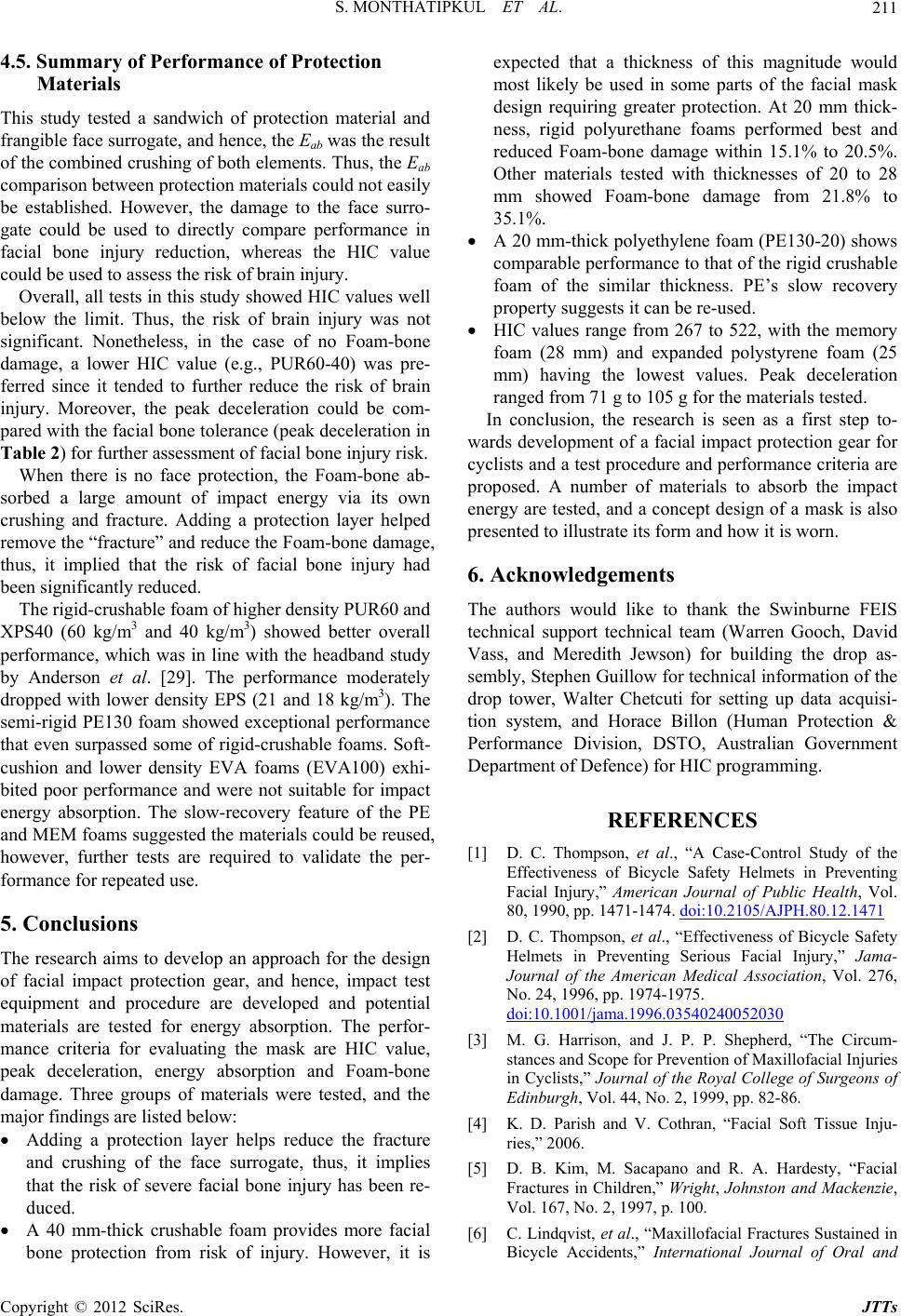 S. MONTHATIPKUL ET AL. 211 4.5. Summary of Performance of Protection Materials This study tested a sandwich of protection materia ible face sur l an frangrogate, and hence, the Eab was the resu The research aims to develop an approach for the design ection gear, and hence, impact test d that a thickness of this magnitude would the similar thickness. PE’s slow recovery deceleration re pr eam (Warren Gooch, David ) for building the drop as- [1] D. C. Thompson, et al., “A Case-Control Study of the Effectiveness ets in Preventing Facial Injury,”ublic Health, Vol. d lt most likely be used in some parts of the facial mask design requiring greater protection. At 20 mm thick- ness, rigid polyurethane foams performed best and reduced Foam-bone damage within 15.1% to 20.5%. Other materials tested with thicknesses of 20 to 28 mm showed Foam-bone damage from 21.8% to 35.1%. A 20 mm-thick polyethylene foam (PE130-20) shows comparable performance to that of the rigid crushable foam of of the combined crushing of both elements. Thus, the Eab comparison between protection materials could not easily be established. However, the damage to the face surro- gate could be used to directly compare performance in facial bone injury reduction, whereas the HIC value could be used to assess the risk of brain injury. Overall, all tests in this study showed HIC values well below the limit. Thus, the risk of brain injury was not significant. Nonetheless, in the case of no Foam-bone damage, a lower HIC value (e.g., PUR60-40) was pre- ferred since it tended to further reduce the risk of brain injury. Moreover, the peak deceleration could be com- pared with the facial bone tolerance (peak deceleration in Table 2) for further assessment of facial bone injury risk. When there is no face protection, the Foam-bone ab- sorbed a large amount of impact energy via its own crushing and fracture. Adding a protection layer helped remove the “fracture” and reduce the Foam-bone damage, thus, it implied that the risk of facial bone injury had been significantly reduced. The rigid-crushable foam of higher density PUR60 and XPS40 (60 kg/m3 and 40 kg/m3) showed better overall performance, which was in line with the headband study by Anderson et al. [29]. The performance moderately dropped with lower density EPS (21 and 18 kg/m3). The semi-rigid PE130 foam showed exceptional performance that even surpassed some of rigid-crushable foams. Soft- cushion and lower density EVA foams (EVA100) exhi- bited poor performance and were not suitable for impact energy absorption. The slow-recovery feature of the PE and MEM foams suggested the materials could be reused, however, further tests are required to validate the per- formance for repeated use. 5. Conclusions of facial impact prot equipment and procedure are developed and potential materials are tested for energy absorption. The perfor- mance criteria for evaluating the mask are HIC value, peak deceleration, energy absorption and Foam-bone damage. Three groups of materials were tested, and the major findings are listed below: Adding a protection layer helps reduce the fracture and crushing of the face surrogate, thus, it implies that the risk of severe facial bone injury has been re- duced. A 40 mm-thick crushable foam provides more facial bone protection from risk of injury. However, it is expecte property suggests it can be re-used. HIC values range from 267 to 522, with the memory foam (28 mm) and expanded polystyrene foam (25 mm) having the lowest values. Peak ranged from 71 g to 105 g for the materials tested. In conclusion, the research is seen as a first step to- wards development of a facial impact protection gear for cyclists and a test procedure and performance criteria a oposed. A number of materials to absorb the impact energy are tested, and a concept design of a mask is also presented to illustrate its form and how it is worn. 6. Acknowledgements The authors would like to thank the Swinburne FEIS technical support technical t Vass, and Meredith Jewson sembly, Stephen Guillow for technical information of the drop tower, Walter Chetcuti for setting up data acquisi- tion system, and Horace Billon (Human Protection & Performance Division, DSTO, Australian Government Department of Defence) for HIC programming. REFERENCES of Bicycle Safety Helm American Journal of P 80, 1990, pp. 1471-1474. doi:10.2105/AJPH.80.12.1471 [2] D. C. Thompson, et al., “Effectiveness of Bicycle Safety Helmets in Preventing Serious Facial Injury,” Jama- Journal of the American Medical Association, Vol. 276, No. 24, 1996, pp. 1974-1975. doi:10.1001/jama.1996.03540240052030 [3] M. G. Harrison, and J. P. P. Shepherd, “The Circum- stances and Scope for Prevention of Maxillofacial Injuries in Cyclists,” Journal of the Royal College of Surgeons of esty, “Facial . 2, 1997, p. 100. Bicycle Accidents,” International Journal of Oral and Edinburgh, Vol. 44, No. 2, 1999, pp. 82-86. [4] K. D. Parish and V. Cothran, “Facial Soft Tissue Inju- ries,” 2006. [5] D. B. Kim, M. Sacapano and R. A. Hard Fractures in Children,” Wright, Johnston and Mackenzie, Vol. 167, No [6] C. Lindqvist, et al., “Maxillofacial Fractures Sustained in Copyright © 2012 SciRes. JTTs  S. MONTHATIPKUL ET AL. Copyright © 2012 SciRes. JTTs 212 005-9 Maxillofacial Surgery, Vol. 15, No. 1, 1986, pp. 12-18. doi:10.1016/S0300-9785(86)80 of Biomechan -9290(95)80001-8 [7] Standards Australia and Standards New Zealand, “AS/ NZS 2063:2008, Bicycle Helmets,” Australian/New Zea- land Standard, 2008. [8] D. Hampson, “Facial Injury: A Reviewical Studies and Test Procedures for Facial Injury Assess- ment,” Journal of Biomechanics, Vol. 28, No. 1, 1995, pp. 1-7. doi:10.1016/0021 sing Hybrid I [9] J. W. Melvin, et al., “A Biomechanical Face for the Hy- brid III Dummy,” Stapp Car Crash Conference Proceed- ings, Vol. 39, 1995, pp. 140-151. [10] T. R. Perl, et al., “Deformable Load SenII Face,” Stapp Car Crash Conference Proceedings, Vol. 33, 1989, pp. 29-42. doi:10.4271/892427 [11] G. W. Nyquist, et al., “Facial Impact Tolerance and Re- esponse—A Com- lmet Drop Test,” Australian/New Zealand The Effectiveness of Bicycle Helm cle Helmet Shock Absorption,” s and Helmets,” Composites Science sponse,” Stapp Car Crash Conference Proceedings, Vol. 30, 1986, pp. 379-400. [12] D. L. Allsop, et al., “Facial Impact R parison of the Hybrid III Dummy and Human Cadaver,” Stapp Car Crash Conference Proceedings, Vol. 32, 1988, pp. 139-155. [13] Standards Australia and Standards New Zealand, “AS/ NZS 2512.3.1:2007, Methods of Testing Protective Hel- mets, Method 3.1: Determination of Impact Energy At- tenuation—He Standard, 2007. [14] R. Anderson, et al., “Further Development of a Protective Headband for Car Occupants,” Australian Transport Safe- ty Bureau, 2001. [15] M. Henderson, “ets: A Review,” Bicycle Helmet Safety Institute, 1995. [16] A. Gale and N. J. Mills, “Effect of Polystyrene Foam Liner Density on Motorcy Plastics and Rubber Processing and Applications, Vol. 5, No. 2, 1985, pp. 101-108. [17] A. L. Yettram, et al., “Materials for Motorcycle Crash Helmets—A Finite Element Parametric Study,” Plastics and Rubber Processing and Applications, Vol. 22, No. 4, 1994, pp. 215-221. [18] N. J. Mills, et al., “Polymer Foams for Personal Protec- tion: Cushions, Shoe and Technology, Vol. 63, No. 16, 2003, pp. 2389-2400. doi:10.1016/S0266-3538(03)00272-0 [19] D. E. Morgan and L. S. Szabo, “Improved Shock Ab- sorbing Liner for Helmets,” Australian Transport Safety Helmets,” Journal of Sports Sciences, Vol. Bureau, 2001. [20] R. A. Stretch, “The Impact Absorption Characteristics of Cricket Batting 18, No. 12, 2000, pp. 959-964. doi:10.1080/026404100446766 [21] T. Takeda, et al., “The Influence acteristics on Impact Force an of Impact Object Char- d Force Absorption by Mouthguard Material,” Dental Traumatology, Vol. 20, No. 1, 2004, pp. 12-20. doi:10.1111/j.1600-4469.2004.00210.x [22] N. K. Cummins and I. R. guard Design on Stresses in the Tooth- Spears, “The Effect of Mouth- Bone Complex,” Medicine & Science in Sports & Exercise, Vol. 34, No. 6, 2002, pp. 942-947. doi:10.1097/00005768-200206000-00006 [23] N. T. Paterson, et a Mechanics of Sports Mouthguards,” Sport l., “A Finite Element Study of the s Engineering, ion of Interior Padding Op- ent of Transporta- . ., “The Impact-Absorbing Effects of Facial - Vol. 7, No. 4, 2004, pp. 182-195. [24] B. G. McHenry, “Head Injury Criterion and the ATB,” ATB Users’ Group, 2004. [25] A. J. McLean, et al., “Prevention of Head Injuries to Car Occupants: An Investigat tions,” University of Adelaide, 1997. [26] D. Tyrell, K. Severson and B. Marguis, “Passenger Train Crashworthiness Studies,” US Departm tion, 1995. [27] T. J. Rupp, M. Bednar and S. Karageanes, “Facial Frac- tures,” 2011 http://emedicine.medscape.com/article/84613-overview [28] K. F. Lee, et al Fractures in Closed-Head Injuries,” Journal of Neuro surgery, Vol. 66, No. 4, 1987, pp. 542-547. doi:10.3171/jns.1987.66.4.0542 [29] R. Anderson, G. Ponte and L. Streeter, “Develop Head Protection for Car Occupa ment of nts,” University of Ade- laide, 2002.
|