Circuits and Systems
Vol.07 No.09(2016), Article ID:68622,14 pages
10.4236/cs.2016.79201
Harmonic Minimization in Seven-Level Cascaded Multilevel Inverter Using Evolutionary Algorithm
Jeyabharath Rajaiah1, Velmurugan Ramar2, Veena Parasunath1
1Department of EEE, KSR Institute for Engineering and Technology, Tamilnadu, India
2Department of EEE, PAC Ramasamy Raja Polytechnic College, Tamilnadu, India

Copyright © 2016 by authors and Scientific Research Publishing Inc.
This work is licensed under the Creative Commons Attribution International License (CC BY).
http://creativecommons.org/licenses/by/4.0/


Received 18 April 2016; accepted 10 May 2016; published 19 July 2016
ABSTRACT
Inverters are power electronic devices that change over DC to sinusoidal AC quantity. Be that as it may, in down to earth, these devices produce non-sinusoidal yield which contains harmonics, so as to blend a close sinusoidal component and to lessen the harmonic distortion multilevel inverters developed. Mathematical methods, which were developed, are derivative based and need initial considerations. To overcome this, evolutionary algorithms, which are derivative free and accurate, were developed for obtaining multi levels of output voltage. The proposed work uses two evolutionary algorithms, namely, Genetic Algorithm (GA) and Particle Swarm Optimization (PSO) algorithm. These algorithms are used to generate the switching angles by satisfying the non linear transcendental equations that govern the low order harmonic components. A seven level cascaded full bridge inverter is designed using MATLAB/Simulink and the results validate the results for switching angles. The Total Harmonic Distortion (THD) value obtained for GA and PSO is 11.81% and 10.84% respectively. The solution obtained from GA algorithm was implemented in hardware using dsPIC controller to validate the simulation results. The THD value obtained for cascaded seven-level multilevel inverter in the hardware prototype is 25.9%.
Keywords:
Multilevel Inverter, Selective Harmonic Elimination, Genetic Algorithm, Particle Swarm Optimization, Harmonic Minimization

1. Introduction
The inverters are relied upon to give sinusoidal yields yet the viable inverters produce non-sinusoidal yield and subsequently contain harmonics. So to combine a close sinusoidal component and to lessen the harmonic distortion multilevel inverters have emerged. It is this creating innovation that has affected the battery packs in electric vehicles in light of the likelihood of high power rating without the utilization of transformer. Among the different multilevel structures that were introduced by researchers, the cascaded multilevel inverter turns out to be much predominant in harmonic reduction. Further, the low order harmonic contents which are available can be minimized by exchanging switching strategies.
Selective Harmonic Elimination Pulse Width Modulation (SHEPWM) technique was developed for multilevel converters to eliminate lower order harmonics. The trigonometric terms in the equations create multiple solutions thereby, making it complex to control the switching angle and hence reduce the lower order harmonics. The arithmetic solutions which are the switching angles of inverter suppress the lower order harmonics. Research was carried out to solve these equations by mathematical methods and evolutionary algorithms. Mathematical methods are derivative based and needs initial assumptions. Different topologies like diode-clamped inverter, capacitor-clamped, and cascaded multilevel inverter with separate DC sources were developed [1] . An optimal modulation technique [2] to reduce the switching losses was proposed, but this technique had more conduction losses due to high output currents and due to the series connection of several semiconductors.
Despite the fact that different novel algorithms for Selective Harmonic Elimination were created [3] [4] , yet they slacked in the capacity to take out substantial number of low order harmonics. This lead to the advancements in selective harmonic elimination pulse width modulated technique based on the foraging behavior of a colony of ants [5] . This method has improved calculation, subordinate free operation, and achieves close optimal convergence. A generalized formulation for selective harmonic elimination pulse width modulation control suitable for high voltage, high power cascaded multilevel Voltage Source Converters (VSC) with both equivalent and non square with DC sources utilized as a part of constant frequency utility applications was produced in relationship with genetic algorithm [6] . The formulation has improved the execution of the framework. Further it offers the benefits of the Hybrid Real Coded Genetic Algorithm (HRCGA) in finding the ideal answer for the nonlinear mathematical statement framework with fast and guaranteed convergence. It is affirmed that numerous autonomous arrangements of solutions exist.
Particle swarm optimization emerged as the next approach for selective harmonic elimination. Species based Particle Swarm Optimization (SPSO) was introduced for harmonic minimization in multilevel inverters that includes nonlinear supernatural mathematical statements having various neighborhood minima however it emerged as a complex optimization issue [7] . PSO methodology was produced for framework with unequal DC sources [8] [9] , however this brought on expansion in the quantity of switching angles. The PSO approach lessened the computational weight for low number of switching angles comprehending the asymmetry of the supernatural comparisons. As most PSO algorithms utilize a solitary learning design for all particles, a Self- Learning Particle Swarm Optimizer (SLPSO), for worldwide advancement issues was displayed [10] , where every particle has an arrangement of four procedures to adapt to various circumstances in the pursuit space. This versatile choice instrument is acquainted with empower particles to pick consequently the fitting learning objective at the suitable minute amid the inquiry process.
Different topologies of multilevel inverter were developed to reduce switching losses and conduction losses, the primary being the harmonic reduction in the output. The selective harmonic elimination which emerged out as one of the best ways had the issues of lower order harmonics making way to optimization techniques like GA & PSO. GA has more computational time but it obtains better results with fast and guaranteed convergence for nonlinear frameworks. Similar to GA, PSO also provides optimal solutions with less computations and supports system even with unequal DC sources.
Considering the advantages of the evolutionary algorithms, this work is proposed to minimize the fifth and seventh order harmonics in the yield voltage of cascaded multilevel inverter by utilizing SHEPWM. In the proposed work seven level multilevel inverter with MOSFET is developed with selective harmonic elimination PWM to reduce the fifth and seventh order harmonics. The switching angles of the MOSFET are suitably controlled to produce the seven levels of output. This system which depends on harmonics disposal hypothesis is utilized to decide the switching angles where low order harmonics can be wiped out. The switching angles are controlled and chosen optimally by the evolutionary techniques. The modulation index available by using PSO technique is more than that of GA. The proposed system is implemented in hardware using dsPIC controller and the result validate better performance. Further the results obtained by settling comparisons acquired from SHEPWM utilizing evolutionary algorithms GA and PSO, gives optimum solution and decreased total harmonic distortion.
2. Cascaded Multilevel Inverter
A Multilevel inverter has a few favorable circumstances over a traditional two level inverter that uses fundamental switching frequency pulse width modulation (PWM) approach. Multilevel inverter is utilized to blend a close sinusoidal voltage from a few levels of dc voltages, regularly acquired from battery sources. As the quantity of levels builds, the incorporated yield waveform has more steps, which deliver a staircase wave that methodologies a fancied waveform. Additionally, as more steps are added to the waveform, the harmonic distortion of the yield wave diminishes, drawing nearer zero as the quantity of level increments. As the quantity of levels expands, the voltage that can be spread over by summing numerous voltage levels additionally increments..
The conventional multilevel inverter topologies created incorporate Diode Clamped Multilevel Inverter, Capacitor Clamped Multilevel Inverter and Cascaded H-Bridge Multi level Inverter. Of these sorts, Cascaded H- bridge inverter creates about sinusoidal voltage from particular DC sources and has least number of segments. Thus the seven-level inverter is acquired from Cascaded H-Bridge Multilevel Inverter (CHBMLI) topology. In this work, fundamental switching frequency scheme is used for modulation rather than high switching frequency. The main advantages of fundamental switching frequency scheme are that it achieves low switching losses and low voltage stresses. The SHEPWM technique is used in the proposed work and the non linear mathematical statements that are obtained from SHEPWM are solved using GA and PSO.
The general piece outline of the proposed framework is appeared in Figure 1. It comprises of a DC Source, Cascaded Multilevel Inverter, SHEPWM Technique and Evolutionary Algorithms. The information is sustained from a DC source to the inverter. The cascaded multilevel inverter comprises of three H-bridges which are associated in series to get the seven-level yield. The yield is sustained to the AC load. The switching pulses for the switches are given from the switching circuit. The non linear mathematical statements acquired from SHEPWM procedure are solved by evolutionary algorithms to give the essential switching angles to the switches of the cascaded multilevel inverter.
2.1. Cascaded Seven Level H-Bridge Multilevel Inverter
A cascaded multilevel inverter has of number of H-Bridge inverter units associated in series and they are sustained from discrete DC sources. As the yield is taken in series, the DC sources must be isolated from each other. Therefore, CHBMLIs is additionally been proposed to be utilized with energy components or photovoltaic clusters keeping in mind the end goal to accomplish higher voltage levels. The subsequent AC yield voltage is the expansion of the voltages produced by various H-Bridge cells. Each H-Bridge has the property to create three

Figure 1. Block diagram of the proposed cascaded seven level inverter.
voltage levels as +Vdc, 0, −Vdc by associating the DC source to the AC yield and by various mixes of four switches where Vdc is the input voltage of the H-Bridge. This proposed topology is utilized for getting seven- level cascaded H-Bridge multilevel inverter.
A seven-level multilevel inverter is acquired by cascading three H-bridge inverter circuits with every H-bridge nourished from a different DC source. The quantity of yield levels m in every stage is identified with number of H-bridge inverter unit’s “n” by Equation (1).
 (1)
(1)
where, m is the No. of level of inverter, n is the No. of full bridge connected in series.
To get the said seven-level yield, the above switching pattern is utilized. The yield voltage waveform of seven- level inverter is as appeared in Figure 3 with α1, α2 and α3 speaking to the switching angles which are utilized for harmonic reduction. By phase shifting the switching time of the positive and negative phase legs of the inverter, a quasi square waveform is generated by each full bridge as shown in Figure 3.
Here number of levels (m) is seven thus number of full bridge inverter circuits associated in series is three which is known from the Equation (1). The single phase seven-level topology of cascaded H-bridge multilevel inverter is as appeared in Figure 2. As each H-bridge is nourished with the same estimation of DC voltage it is called as symmetrical cascaded multilevel inverter. The DC voltages can be acquired from batteries; capacitors or power supplies. The phase yield voltage is the whole of three inverter yields. The seven-level yield waveform is acquired by various switching combinations. The switching pattern for single phase seven-level topology of cascaded H-bridge multilevel inverter is appeared in Table 1.
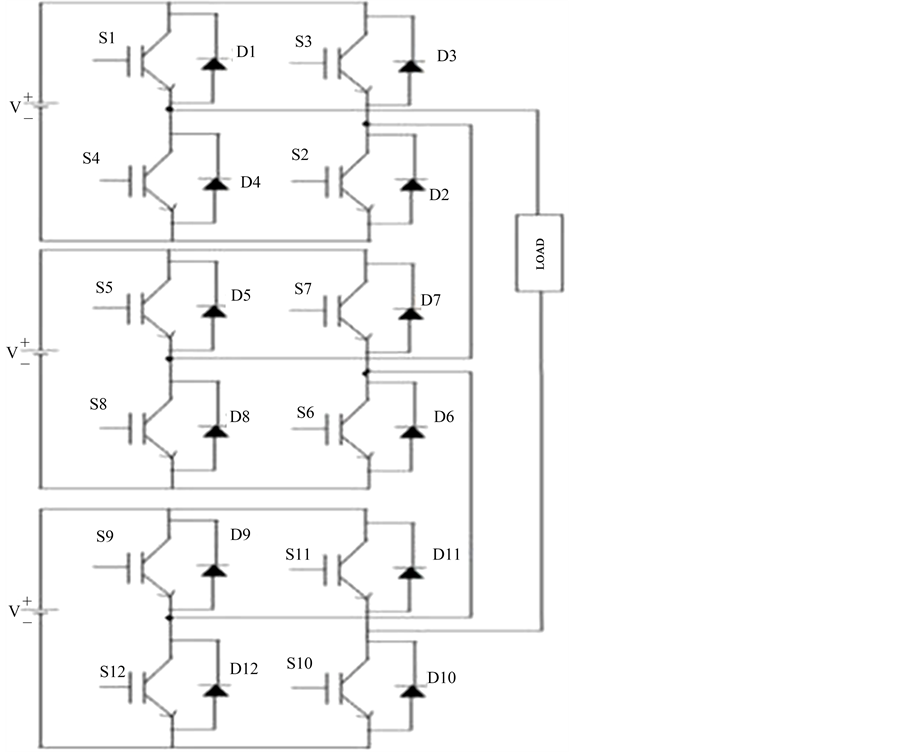
Figure 2. Single phase 7-level topology of cascaded H-bridge multi level inverter.

Table 1. Switching pattern for single phase 7-sevel Cascaded H bridge multilevel inverter.
2.2. Selective Harmonic Elimination PWM
The selective harmonic elimination PWM technique is based on the fundamental switching frequency theory and dependent on the elimination of defined harmonic content orders. The primary thought of this technique depends on characterizing the switching angles of harmonic orders to dispense with and getting the Fourier series expansion of the yield voltage. This permit lower switching frequencies to be utilized which prompted lower switching misfortunes and higher effectiveness. When all is said in done Fourier series is given the Equation (2).
 (2)
(2)
For this situation Fourier series extension of yield voltage waveform is given by Equation (2) as takes after,
 (3)
(3)
where an = a0 = 0 (due to quarter wave symmetry)
 (4)
(4)
From Figure 3 for quasi square wave Equation (4) is given as follows
 (5)
(5)
On solving Equation (5) we get
 (6)
(6)
For seven level cascaded multilevel inverter for three DC sources comparison is given
 (7)
(7)
where n = 1, 5, 7 and s = 3 which speaks to number of DC sources. The goal of SHEPWM is to wipe out low order harmonics. In this number of harmonics that can be wiped out is equivalent to s − 1 i.e., 2 so fifth and seventh harmonics are taken. Along these lines, to fulfill the fundamental harmonic component and to dispense with the fifth and seventh harmonics, Equation (7) is extended as three nonlinear mathematical statements with three angles as gave in Equations (8)-(10).
 (8)
(8)
 (9)
(9)
 (10)
(10)

Figure 3. Yield voltage waveform of 7-level cascaded multilevel inverter.
In the mathematical statement (8)-(10), to dispense with fifth and seventh harmonic V5 and V7 are set to zero so that comparisons (11)-(13) are acquired. To decide the switching angles the accompanying mathematical statements must be illuminated,
 (11)
(11)
 (12)
(12)
 (13)
(13)
Here M speaks to modulation index changes from 0 to 1. The switching angles α1, α2 and α3 must be not exactly π/2. The comparisons are fathomed by Newton Raphson strategy and resultant hypothesis in the writing. In any case, it is tedious and needs starting supposition for unraveling the mathematical statements. Consequently evolutionary algorithms are utilized for explaining this kind of non linear mathematical statements.
3. Evolutionary Algorithms
Numerical streamlining has less exactness and the challenges connected with them have prompted the approach of evolutionary based algorithms for seeking close optimum solutions. These calculations emulate the similitude of regular organic advancement and/or the social conduct of species. Some evolutionary algorithms that were embraced for optimizing engineering problems include genetic algorithms, ant colony techniques, particle swarm optimization, leaping frog techniques and so on. These algorithms depend on how ants locate the most brief course to a wellspring of nourishment and how winged creatures discover their destination amid relocation. The conduct of the species is guided by learning, adjustment, and advancement. By emulating the productive conduct of these species, different computational frameworks were created to accomplish quick and vigorous answers for complex optimization issues.
Genetic Algorithm Based SHEPWM
The primary developmental strategy that was created is the genetic algorithm which depends on the Darwinian’s standard of the survival of the fittest and the common procedure of advancement through multiplication. The chromosome gives the arrangement of the mind boggling issue and is spoken to as a string. Every chromosome comprises of an arrangement of components, called genes which hold the qualities for the optimization variables. The wellness of every chromosome is dictated by assessing it against an objective function. To accomplish the normal survival of the fittest, best chromosomes will trade information between them to deliver the offspring chromosomes. The offspring solutions are then assessed and are utilized to advance another era of populace on the off chance that they give preferable arrangements over powerless populace individuals. This procedure is proceeded for countless to acquire a best fit solution.
The execution of GAs is influenced by the populace size, number of eras, crossover rate, and mutation rate. Bigger populace size and expansive number of eras will improve the probability of acquiring a worldwide optimum solution, yet it will likewise increase the processing time. In crossover, the parent’s information gets traded to deliver an offspring. A sudden change to an offspring which is finished by the process of mutation is rare. This should be possible self-assertively transforming a portion of the information in arbitrarily chose chromosome. The advantage of change is that it genetic acquaints new genetic material to the evolutionary process, maybe in this manner staying away from stagnation around neighborhood minima. The progressions for figuring an issue and applying a GA for settling nonlinear mathematical statements are as per the following:
Ø Select binary or floating point strings.
Ø The number of variables speaks to the quantity of genes in a chromosome. In the proposed work, the quantity of variables is the quantity of H-bridges in a cascaded multilevel inverter as they demonstrate the quantity of controllable switching angles. A seven-level inverter requires three H-bridges and thus, every chromosome will have three switching angles
Ø Set a populace measure and introduce the populace. The populace utilized here is 20 chromosomes, each containing three switching angles. The populace is introduced with arbitrary angles between 0 degree and 90 degree thinking about the quarter wave symmetry of the yield voltage waveform.
Ø The objective function for the GA is the fitness of every chromosome. The fundamental goal of this work is to minimize specified harmonics; and henceforth the objective function is identified with these harmonics. The harmonics taken here are fifth and seventh harmonics subsequently objective function is given as in Equation (14).
 (14)
(14)
The fitness value (FV) is given by Equation (15) which is as follows
 (15)
(15)
The switching angle set delivering the minimum FV is the best arrangement of the emphases. The GA is normally set to keep running for a specific number of emphases (100 for this situation) to discover an answer. After the principal emphasis, FVs are utilized to decide new offspring. These experience crossover and mutation operations and another populace is made which experiences the same cycle beginning from FV assessment until the arrangement is found that fulfill the limitations. These are the strides utilized for explaining nonlinear comparisons utilizing GA. The best arrangement is the switching angle set creating the minimum FV. Out of 100 cycles, the main emphasis is utilized to decide the new offspring. The new ones experience mutation and crossover and make another populace. This new populace is further assessed and the system is rehashed beginning from FV until the arrangement is found that fulfills the imperatives.
4. Particle Swarm Optimization Based SHEPWM
Particle swarm optimization is an aggregate framework that has been connected effectively to wide assortment of search and optimization issues. PSO is a learning strategy enlivened by feathered creatures rushing in the inquiry of sustenance. It was advanced initially by James Kennedy and Eberhart in 1995. PSO comprises of various particles (winged creatures) that move on the whole on the pursuit space search of the global optimum. Every fledgling (particle) is portrayed by its position and execution. At first particles are arbitrarily disseminated on the hunt space and move as per neighborhood information. The idea of PSO algorithm is appeared in Figure 4. It can be surmised that particle velocity is summation of the inertia, intellectual segment and social segment. The position redesign is finished by summation of particle velocity and current position.
The PSO is actualized here to illuminate the nonlinear mathematical statements got from SHEPWM. This is accomplished by minimizing the objective function which portrays the particular order harmonics. The fundamental points of interest of executing PSO are anything but difficult to actualize, couple of parameters to modify and productive in global search. Here every particle is described by the estimation of the variable and comparing

Figure 4. Concept of PSO algorithm.
estimation of the function. The switching angles for seven-level multilevel inverter are considered as the solution of PSO calculation. The orderly technique for executing PSO is as per the following:
Ø The populace size (=20 particles) and the most extreme number of cycles which are the key parameters of PSO are initialized.
Ø Each particle in the populace is haphazardly instated somewhere around 0 and 1/2.
Ø Initialize the velocity, individual best, worldwide best and emphasis tally.
Ø The fitness value at every particle position is assessed which is given by Equation (15).
Ø For every particle figure the velocities taking into account the individual best and worldwide best position as given in Equation (16).
 (16)
(16)
Update the particle position by the Equation (17).
 (17)
(17)
The iterations are repeated until it satisfies the Equation (17). The main advantages of implementing PSO are easy to implement, few parameters to adjust and efficient in global search.
5. Simulation Results
The seven-level cascaded multilevel inverter utilizing GA and PSO is actualized in simulation utilizing MATLAB/Simulink. The m-file is utilized to compose the algorithm codes for comprehending the comparisons and to acquire the switching angles. The obtained switching angles are actualized in Simulink using simpower frameworks tool compartment.
The GA algorithm has obtained the switching angles by fluctuating the modulation index from 0.4 - 0.8 appeared in Figure 5. For the other M, it has no solution. It has single solution for number of cycles. In Figure 6 the switching angles got from PSO shifts from M is 0.1 - 0.2. It has gotten answers for extensive variety of modulation indexes. The model of single stage seven-level cascaded multilevel inverter is examined beneath with the switching states of different switches. The switching pulses are given taking into account the yield of GA and PSO. The single stage non linear RL load is considered for examining the harmonic substance. As the

Figure 5. Switching angles for various modulation index for GA.

Figure 6. Switching angles for various modulation index for PSO.
input voltages for all the three full bridge inverters are same, it is called as symmetrical cascaded multilevel inverter. The load voltage sign is associated with workspace apparatus for performing the harmonic examination for load voltage waveform. Every full bridge inverter is encouraged with 24V DC input for both PSO and GA algorithm.
The yield current waveform with seven levels is gotten from the multilevel inverter which is as appeared in Figure 7. The yield voltage is 72 V which is thrice the input voltage which is appeared in Figure 8. The seven levels of the yield are gotten as the staircase waveform by the diverse switching combinations. The yield current got is 0.72 A. The yield is taken crosswise over RL load thus it is as sinusoidal wave. It finishes one cycle at 0.024 seconds as it is lagging load. The Fast Fourier Transform (FFT) investigation is done to gauge the THD esteem. The FFT examination on the yield voltage waveform with RL load is appeared in Figure 9.
From this it can be induced that the fifth and seventh harmonic is lessened beneath 1% and the THD acquired is 11.51%. This demonstrates the viability of the proposed algorithm. The FFT examination is likewise done to
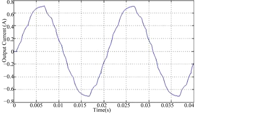
Figure 7. Simulation result for yield current waveform of seven level cascaded MLI.

Figure 8. Simulation result for yield voltage waveform of seven level cascaded MLI.

Figure 9. FFT Analysis of output voltage for GA with RL load.
gauge the THD estimation of the yield voltage by PSO to discover the extent of individual harmonic orders. The FFT investigation for the yield voltage waveform with RL load is appeared in Figure 10. In this fifth harmonic substance is under 1% however the seventh harmonic more prominent than 3% in this manner violating IEEE standards for harmonic distortion. The THD value got is 10.84% using PSO. The principle goal of this work is to wipe out the low order harmonics like fifth and seventh order harmonics. The THD acquired from PSO is low contrasted with GA however the seventh order harmonics in PSO damages the IEEE standard of individual harmonic distortion which must be under 3%. Thus the switching angles acquired from GA are actualized in hardware to validate the simulation results.
6. Hardware Results
The seven-level cascaded multilevel inverter is actualized in hardware with MOSFET switches and dsPIC- 30F4011 controller. The different results got for cascaded multilevel inverter like the input voltage, switching pulses and the yield voltage waveforms from the digital storage oscilloscope are introduced in this segment. The harmonic investigation for yield voltage waveform got from power quality analyzer is additionally introduced. In order to obtain the shaped 7-level output without distortion, MOSFET block parameters in MATLAB should vary according to the load used. Here for 10 ohm resistive load, MOSFET block parameters are set as follows: FET resistance = 0.01 ohms, internal diode resistance = 10 kiloohms.
The multilevel inverter converts DC input into AC output. The seven-level AC yield waveform is accomplished utilizing cascaded H-Bridge topology. The yield voltage waveform for seven-level cascaded multilevel inverter is appeared in Figure 11. The yield voltage got from cascaded multilevel inverter is 71 V in hardware setup which is low contrasted with simulation results because of nearness of switching losses in the hardware. The yield voltage is regulated using voltage feedback which is bolstered to the controller. The yield voltage got from cascaded multilevel inverter is 71 V which can’t be encouraged to AC motor. So the yield voltage is expanded up to 230 V utilizing step up transformer.
The harmonic substance in the yield waveforms are for the most part dissected by power quality analyzer. Here the harmonic spectrum of yield voltage waveform for seven-level cascaded multilevel inverter without filter got utilizing power quality analyzer is appeared in Figure 12. The THD value got in the hardware model from cascaded multilevel inverter without filter is 25.9% and the low order harmonics are decreased beneath 3%. The THD value acquired for the cascaded multilevel inverter with filter is 1.9% and the low order harmonics are totally disposed of which is appeared in Figure 13.
THD got for seven-level cascaded multilevel inverter is 11.51% in simulation yet in hardware it is 25.9% without filter and 1.9% with filter. The THD is high without filter as there are more commotions in the yield voltage waveform. The examination of simulation and hardware results is appeared in Table 2. A SHEPWM

Figure 10. FFT Analysis of output voltage for PSO with RL load.

Figure 11. Hardware yield voltage waveforms.

Figure 12. Harmonic spectrum of output voltage without filter.
control system is embraced in the switching circuit with GA and PSO to give an adequate control in the inverter yield voltage. The THD got by GA and PSO are 11.51% and 10.84%. The outcomes acquired from GA and PSO are looked at. The fifth and seventh order harmonic got from GA is under 3% which fulfill the IEEE norms yet the low request sounds acquired from PSO is more prominent than 3% that disregarding IEEE standard.

Figure 13. Harmonic spectrum of output voltage with filter.
Table 2. Comparison of simulation and hardware results.
From the examination results with this inverter procedure, the low order harmonics are significantly lessened by the switching angles acquired from GA so it is executed in hardware. To confirm GA solutions, test results are displayed which approve the exactness of the proposed strategy. The harmonic spectrum of the exploratory yield voltage is gotten from the power quality analyzer. The THD got in hardware model for seven-level cascaded multilevel inverter is 25.9% without filter and 1.9% with filter. At the point when contrasted with simulation comes about, the THD is high because of nearness of clamors in the yield voltage waveform.
7. Conclusion
A summed up recipe of SHEPWM suitable for high power high voltage cascaded multilevel converters with equivalent DC voltage sources was proposed and exhibited in this paper. A complete simulation model of a cascaded multilevel inverter has been proposed utilizing MATLAB/Simulink programming. A SHEPWM control method is embraced in the switching circuit with GA and PSO to give a worthy control in the inverter yield voltage. The THD got by GA and PSO is 11.51% and 10.84% respectively. The outcomes got from GA and PSO are analyzed. The fifth and seventh order harmonics got from GA is under 3% which fulfill the IEEE guidelines yet the low order harmonics acquired from PSO is more prominent than 3% that abusing IEEE standard. From the examination results with this inverter procedure, the low order harmonics are considerably decreased by the switching angles got from GA so it is executed in hardware. To confirm GA solution, trial results are exhibited which approve the precision of the proposed technique. The harmonic spectrum of the trial yield voltage is acquired from the power quality analyzer. The THD acquired in hardware model for seven-level cascaded multilevel inverter is 25.9% without filter and 1.9% with filter. At the point when contrasted with simulation results, the THD is high because of nearness of commotions in the yield voltage waveform.
Cite this paper
Jeyabharath Rajaiah,Velmurugan Ramar,Veena Parasunath, (2016) Harmonic Minimization in Seven-Level Cascaded Multilevel Inverter Using Evolutionary Algorithm. Circuits and Systems,07,2309-2322. doi: 10.4236/cs.2016.79201
References
- 1. Rodriguez, J., Lai, J.-S. and Peng, F.Z. (2002) Multilevel Inverters: A Survey of Topologies, Controls, and Applications. IEEE Transactions on Industrial Electronics, 49, 724-738.
http://dx.doi.org/10.1109/TIE.2002.801052 - 2. Malinowski, M., Gopakumar, K., Rodriguez, J. and Perez, M.A. (2010) A Survey on Cascaded Multilevel Inverters. IEEE Transactions on Industrial Electronics, 57, 2197-2206.
http://dx.doi.org/10.1109/TIE.2009.2030767 - 3. Fei, W.M., Ruan, X.B. and Wu, B. (2009) A Generalized Formulation of Quarter Wave Symmetry SHEPWM Problems for Multilevel Inverters. IEEE Transactions on Power Electronics, 24, 1758-1766.
http://dx.doi.org/10.1109/TPEL.2009.2018094 - 4. Fei, W., Du, X. and Wu, B. (2008) A Generalized Half Wave Symmetry SHE-PWM Formulation for Multilevel Voltage Inverters. IEEE Transactions on Industrial Electronics, 57, 3030-3038.
http://dx.doi.org/10.1109/TIE.2009.2037647 - 5. Sundareswaran, K., Jayant, K. and Shanavas, T.N. (2007) Inverter Harmonic Elimination through a Colony of Continuously Exploring Ants. IEEE Transactions on Industrial Electronics, 54, 2558-2565.
http://dx.doi.org/10.1109/TIE.2007.899846 - 6. Dahidah, M.S.A. and Agilities, V.G. (2008) Selective Harmonic Elimination PWM Control for Cascaded Multilevel Voltage Source Converters: A Generalized Formula. IEEE Transactions on Power Electronics, 23, 1620-1630.
http://dx.doi.org/10.1109/TPEL.2008.925179 - 7. Hagh, M.T., Taghizadeh, H. and Razi, K. (2009) Harmonic Minimization in Multilevel Inverters Using Modified Species Based Particle Swarm Optimization. IEEE Transactions on Power Electronics, 24, 2259-2267.
http://dx.doi.org/10.1109/TPEL.2009.2022166 - 8. Kaviani, A., Fathi, S.H., Farokhnia, N. and Ardakani, A. (2010) PSO, an Effective Tool for Harmonic Elimination and Optimization in Multilevel Inverters. Proceedings of the 4th IEEE Conferences on Industrial Electronics and Applications, Xi’an, 25-27 May 2010, 2902-2907.
- 9. Taghizadeh, H. and Tarafdar Hagh, M. (2010) Harmonic Elimination of Cascade Multilevel Inverters with Non Equal DC Sources Using Particle Swarm Optimization IEEE Transactions on Industrial Electronics, 57, 3678-3684.
http://dx.doi.org/10.1109/TIE.2010.2041736 - 10. Li, C.H., Yang, S.X. and Nguyen, T.T. (2012) A Self-Learning Particle Swarm Optimizer for Global Optimization Problems. IEEE Transactions on Systems, Man, and Cybernetics—Part B: Cybernetics, 42, 627-646.
http://dx.doi.org/10.1109/TSMCB.2011.2171946