Paper Menu >>
Journal Menu >>
 Journal of Minerals & Materials Characterization & Engineering, Vol. 10, No.14, pp.1345-1357, 2011 jmmce.org Printed in the USA. All rights reserved 1345 Thermal Cycling Effects on the Fatigue Behaviour of Low Carbon Steel Segun Afokhainu Agbadua 1 , Chinedum Ogonna Mgbemena 1* , Chika Edith Mgbemena 2 , Lazarus Onyebuchi Chima 2 1 National Engineering Design Development Institute, Nnewi, Anambra State, Nigeria 2 Department of Industrial/Production Engineering, Nnamdi Azikiwe University, Awka, Anambra State, Nigeria * Corresponding author: edumgbemena@yahoo.com ABSTRACT This paper examines the behavior of low carbon steels subjected to a frequency thermal cycling test. A compositional analysis was performed to ascertain the percentage of carbon in the as- received materials. The specimens were machined to a precise gauge length and diameter and exposed to various cycles of heat at each temperature. A fatigue test was also performed with the use of Avery Dennison and bending stress was obtained using the curve supplied with the machine. The results from the machine were converted to Mega Pascal (MPa) and the values used to plot S-N curves and fatigue resistance for the specimens at various cycles and different temperatures were established. Keywords: Carbon Steels, fatigue, thermal cycling, Stress, as-received materials. DEFINITION OF TERMS As-received material means the low carbon steel used in this research. Thermal cycling is the alternate heating and cooling of a material. Low frequency thermal cycle is the one in which the time taken for completion of the cycle is large enough to cool the component. Typical examples are ingot moulds and brake drums of railway coaches. High frequency thermal cycle is the one in which the time involved is in milliseconds and the heating and cooling are influenced by the thermal inertia of the system under consideration.  1346 Segun Afokhainu Agbadua Vol.10, No.14 Cylinder heads, piston rings and exhaust manifolds are standing examples of components which experience high frequency thermal cycles. Fatigue Limit is the stress below which a material will not fail for a long period of time. 1. INTRODUCTION The term ‘fatigue’ can be defined as the weakening or breakdown of a material subjected to prolonged or repeated stress. It is a gradual and located irreversible process that occurs in materials under tensions or floating deformations. They are caused by movement disagreements in reticulate crystalline metal, leading to intrusions and extrusion formation. The method S-N is the study of fatigue through stress to number of cycles to failure approach. Low-cycle fatigue tests subject specimens to repeated stress or strain until failure occurs at a relatively small number of cycles. The upper limit in low-cycle life has generally been selected arbitrarily by individual investigators to lie in the range of 10 2 to 10 5 cycles. On the other hand, the lower limit of life is the static test which has been represented by various investigators as one cycle, two cycles, three cycles, four cycles and five cycles. Investigations in low-cycle fatigue are conducted either to provide information concerning a particular problem, or to obtain fundamental information. The effect of thermal cycling on a material cannot be trivialized because of its importance to the design and manufacturing engineer. When a material is subjected to a temperature gradient it tends to expand differentially, during this process thermal stresses are induced. The source of heat that causes the thermal gradient may be friction as in the case of brake. The following are the two types of thermal cycling: - Low frequency thermal cycling - High frequency thermal cycling Thermal cycling process which is the alternate heating and cooling of a material until they experience molecular reorganization which tightens or optimizes the particulate structure of the material throughout, relieving stresses and making it denser and uniform thereby minimizing flaws or imperfections.  Vol.10, No.14 Thermal Cycling Effects on the Fatigue 1347 The tighter structure also enhances the energy conductivity and heat distribution characteristics of the material. It was reported that thermal cycling is followed by the formation of a large number of fine crack (0.1 – 1.0mm long) on the surface of a specimen and these cracks grow with increasing number of thermal cycle [1]. Fatigue studies have been concerned with conditions of service in which failure occurred at more than 10 4 cycles of stress. There is growing recognition of engineering failures which occur at relatively high stress and low numbers of cycles to failure. Fatigue test helps in estimating endurance strength and endurance limit for a metal. Fatigue tests may be performed by subjecting members to repeated axial loads, bending moments or torques. The usual way of presenting low-cycle fatigue test results is to plot the plastic strain range ∆ερ against Ν. A straight line is obtained when plotted on a log-log coordinates as given by [2]. ∆ఌఘ ଶ =ߝ , ݂ሺ2ܰሻܥ (1) Where ∆ఌఘ ଶ = plastic strain amplitude. ߝ , ݂ = fatigue ductility coefficient defined by the strain intercept at 2N = 1. ߝ , ݂ is approximately equal to the true fracture strain εf for many metals. 2N = number of strain reversals to failure (one cycle is two reversals) C = fatigue ductility exponent, which varies between – 0.5 and – 0.7 for many metals. Several attempts have been made to predict the fatigue strength for variable stresses using stress against number of cycle’s curves for constant mean stress conditions. Some of the predictive methods available are very complex but the simplest and best known is “Miner’s Law.” Miner postulated that when a component is fatigued, internal damage takes place and the nature of the damage is difficult to specify but it may help to regard the damage as the slow internal spreading of a crack, although this should not be taken too literally. He also stated that the extent of damage was directly proportional to the number of cycles for a particular stress level and quantified this by adding that “the fraction of the total damage occurring under one series of  1348 Segun Afokhainu Agbadua Vol.10, No.14 cycles at a particular stress level, is given by the ratio of the number of cycles actually endured (n) to the number of cycles (N) required to break the component at the same stress level” [3]. The ratio n/N is called the “cycle ratio” and he proposed that failure takes place when the sum of the cycle ratios equals unity. As expressed mathematically; ∑ ே = 1 Or భ ே భ + మ ே మ + య ே య =⋯ +݁ݐܿ=1 (2) Experience has shown that the order of application of the stress is a matter of considerable importance and that the application of higher stress amplitude first has a more damaging effect on fatigue performance than the application of initial low stress amplitude. In many applications, the total strain range may be known but it may be difficult to separate it into plastic and elastic components, thus a combined equation may be more useful. ∆ߝ ௧ = ∆ߝ +∆ߝ (3) Where, ∆ߝ ௧ , ∆ߝ , ܽ݊݀∆ߝ represent total strain, elastic strain and plastic strain. The relationships between ∆ߝ and ܰ are given above but ∆ߝ may be related to ܰ by the following modified form of Basquin’s Law [4]. ∆ߝ݁ = 3.5ݔ ఙ்ௌ ா ݔܰ ି.ଵଶ (4) When the graph of strain range against number of cycles to failure (N) is plotted, it is observed that the initial part of the curve closely fits the slope of Coffin’s equation while the latter part fits the modified Basquin’s .The cross-over point being at about 10 5 . Some researchers showed that the rate of fatigue crack growth depends on the plastic flow immediately in front of the advancing crack tip, including such parameters as the shear ductility, the yield strength and the yield elongation [5]. The earliest works on thermal stress fatigue loading were done by [6] and they presented what are now referred to as the seminal studies in the area. These investigations provided the theoretical and experimental platform upon which thermal fatigue research would rest until the middle of the 1970s. During this time most work concentrated on determining the effect of  Vol.10, No.14 Thermal Cycling Effects on the Fatigue 1349 temperature on low cycle (or high strain) fatigue strength of materials and production of the appropriate 1 + N curves. The majority of their work was completed using both high temperature isothermal and thermal plus mechanical fatigue testing such as described in [7] utilizing servo-hydraulic test machine. The concentration was on identifying crack initiation for use in life prediction rather than monitoring the crack growth. According to [8] metallic components subjected to thermal cycling/thermal fatigue may fail in one of the following ways: (i) Type 1 failure: Cracks appear first on the hot zone of the component (in the heat- checking net work) and may eventually propagate through the section. This is the most common type of failure observed in grey cast irons and other brittle materials. (ii) Type 2 failure: Severe distortion which ultimately renders the compound useless. This type of failure is usually found in ductile iron components. (iii) Type 3 failure: Gross cracking through the entire section during the first few cycles. These failures emanate due to the mismatching of materials selected, improper design and random thermal cycling. (iv) Type 4 failure: Lowering of mechanical properties of materials due to metallurgical variations such as microstructural changes and internal oxidation which can lead to premature failure of components. In this study, the bending moment approach was used and it was found that if a specimen survived the first load cycle, it ‘Would not fail until a certain “minimum life” was exceeded’. 2. EXPERIMENTAL 2.1 Materials and Sample Preparation The steel used in this study was Fe-0.2045C and is designated as A 1 which is low carbon steel. The chemical compositions of these steels are given in Table 1 below. The materials were supplied in the form of hot-rolled bars. The Carbolite muffle furnace which is a laboratory type of furnace with built-in thermocouple was used in this research.  1350 Segun Afokhainu Agbadua Vol.10, No.14 Table 1: Chemical composition of Low Carbon Steel Run C Si S P Mn Ni Cr Mo V Cu Avg 0.2045 0.1589 0.0444 0.0317 0.5993 0.1066 0.0851 0.0139 0.0014 0.2880 W As Sn Co A1 Pb Ca Zn Fe% Avg 0.0008 0.0033 0.0404 0.0101 0.0001 0.0000 0.0001 0.0044 98.4086 2.2 Thermal Cycling The as-received materials were machined to 50.9 mm in length with gauge length of 52mm in diameter. The as-received materials were subjected to four cycles of heat at different cycling temperatures ranging from air, 120, 360, and 500 respectively. The control experiment was done without subjecting the materials to treatment. The as-received materials which contain different amount of carbon were placed in the furnace. Twenty-four samples of the as-received A 1 were subjected to a furnace temperature of 120 0 C for 30minutes after which the samples were removed from the furnace and cooled in the air to complete the cycles of thermal treatment. Six samples were taken for fatigue test while the remaining 18 samples were loaded into the furnace for the second cycle of thermal treatment. The samples were soaked for 30minutes after which they were brought for cooling. After cooling, six samples were taken for fatigue test. This process was carried for the third and fourth cycle of thermal treatment and the specimen were subjected to the same heat treatment at various temperatures. 2.3 Fatigue Test The fatigue test was done using Avery Denison machine (Avery model 7305). The bending moment was measured. The revolution counter fitted to the motor records the number of stress cycles to failure (N). The calibration curve supplied with the machine was used to show the relationship between dial gauge reading and the imposed torque. The following equation was used to calculate the bending stress  Vol.10, No.14 Thermal Cycling Effects on the Fatigue 1351 ߪ ௦ = ெ ೌೣ ௐ Where ܹ= ݏ݁ܿݐ݅݊݉݀ݑ݈ݑݏ= ܫ= గௗ య ଷଶ ߨ = 3.142 d = specimen diameter (mm) ߪ ௦ = Bending stress (MPa) ܯ ௫ = maximum bending moment (KN-m) The stair case method was used in applying the moment .The applied bending moment was increased by a fixed increment and the next specimen was tested with the new bending moment. That was done to each specimen at a particular cycle and temperature. The fatigue test of the material in air was done for the as-received materials A 1 (i.e. the low carbon steel). The bending moments imposed were 20, 30, 40, 50, 100 and 150 Kgfcm which was converted to KN-m at various temperatures. The bending test was performed at a frequency of 50Hz (1400rpm) for each specimen. It was a complete reversed cycle of stress range (R) and is equal to minimum stress divided by maximum stress which is equal to a negative value (-1) in fatigue tests. Results were obtained at various temperature and they are shown in Table 2. 2.4 The Effect of Thermal Cycling on Fatigue Behavior The stress and number of cycles to failure obtained from the rotary bending fatigue tests of low carbon steels is shown in Table 2. The value from Table 2 was used to plot a smooth curve which was drawn through the data points instead of a straight line. A line of best fit was used to join the data points. Figures 1-5 depicts the curves obtained. In each of the figures, the curves represent points in which samples did not fail after an excess of 10 3 cycles or more stress. Table 2: The values obtained from the Fatigue Experiments of low Carbon Steel at different temperatures and different cycles Temp O C Moment Kgfcm Diamete r (mm) Bend Stress (MPa) Number of cycles to failure (N) Air One cycle Two Cycles Three Cycles Four Cycles 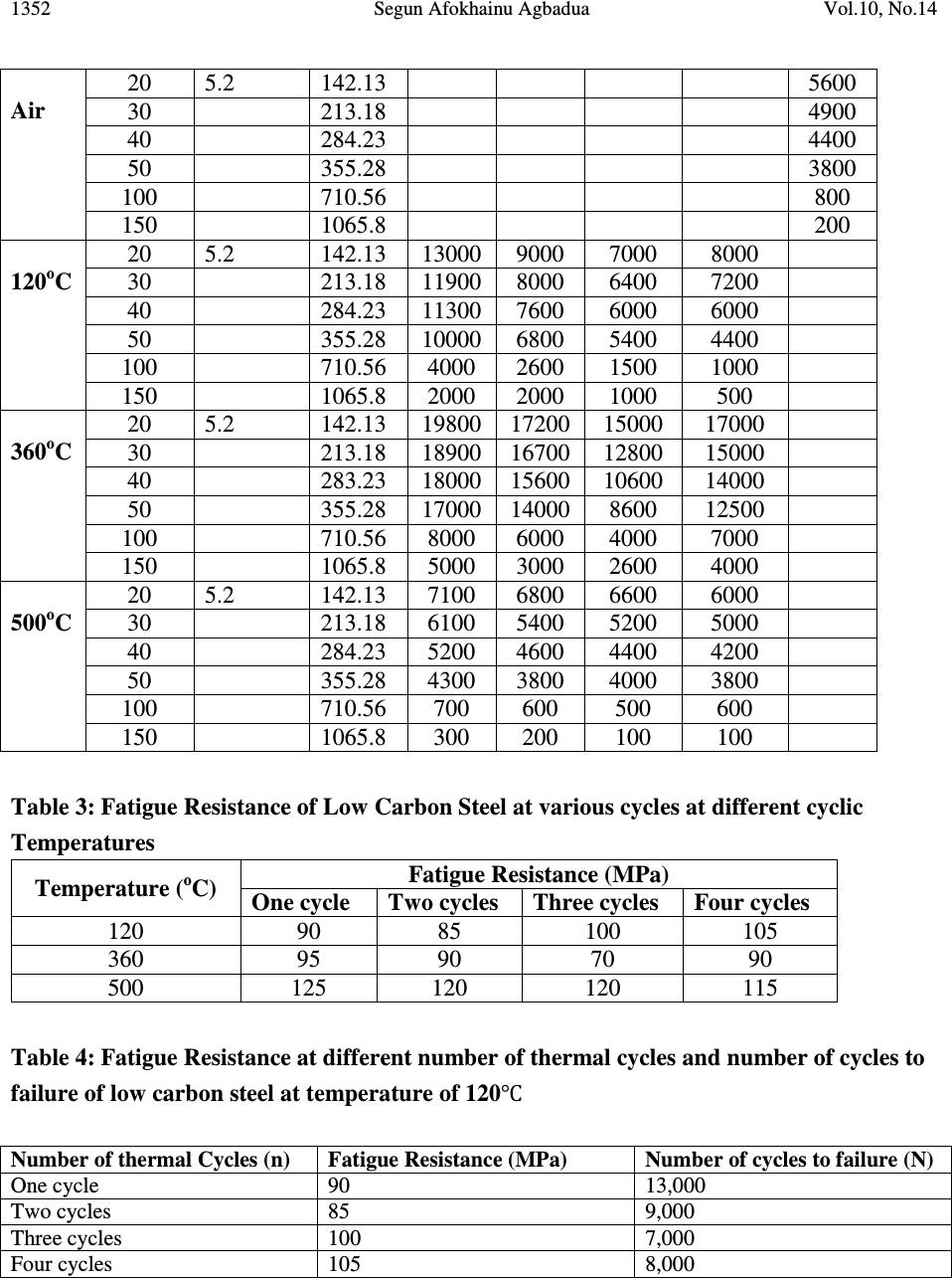 1352 Segun Afokhainu Agbadua Vol.10, No.14 Air 20 5.2 142.13 5600 30 213.18 4900 40 284.23 4400 50 355.28 3800 100 710.56 800 150 1065.8 200 120 o C 20 5.2 142.13 13000 9000 7000 8000 30 213.18 11900 8000 6400 7200 40 284.23 11300 7600 6000 6000 50 355.28 10000 6800 5400 4400 100 710.56 4000 2600 1500 1000 150 1065.8 2000 2000 1000 500 360 o C 20 5.2 142.13 19800 17200 15000 17000 30 213.18 18900 16700 12800 15000 40 283.23 18000 15600 10600 14000 50 355.28 17000 14000 8600 12500 100 710.56 8000 6000 4000 7000 150 1065.8 5000 3000 2600 4000 500 o C 20 5.2 142.13 7100 6800 6600 6000 30 213.18 6100 5400 5200 5000 40 284.23 5200 4600 4400 4200 50 355.28 4300 3800 4000 3800 100 710.56 700 600 500 600 150 1065.8 300 200 100 100 Table 3: Fatigue Resistance of Low Carbon Steel at various cycles at different cyclic Temperatures Temperature ( o C) Fatigue Resistance (MPa) One cycle Two cycles Three cycles Four cycles 120 90 85 100 105 360 95 90 70 90 500 125 120 120 115 Table 4: Fatigue Resistance at different number of thermal cycles and number of cycles to failure of low carbon steel at temperature of 120℃ Number of thermal Cycles (n) Fatigue Resistance (MPa) Number of cycles to failure (N) One cycle 90 13,000 Two cycles 85 9,000 Three cycles 100 7,000 Four cycles 105 8,000 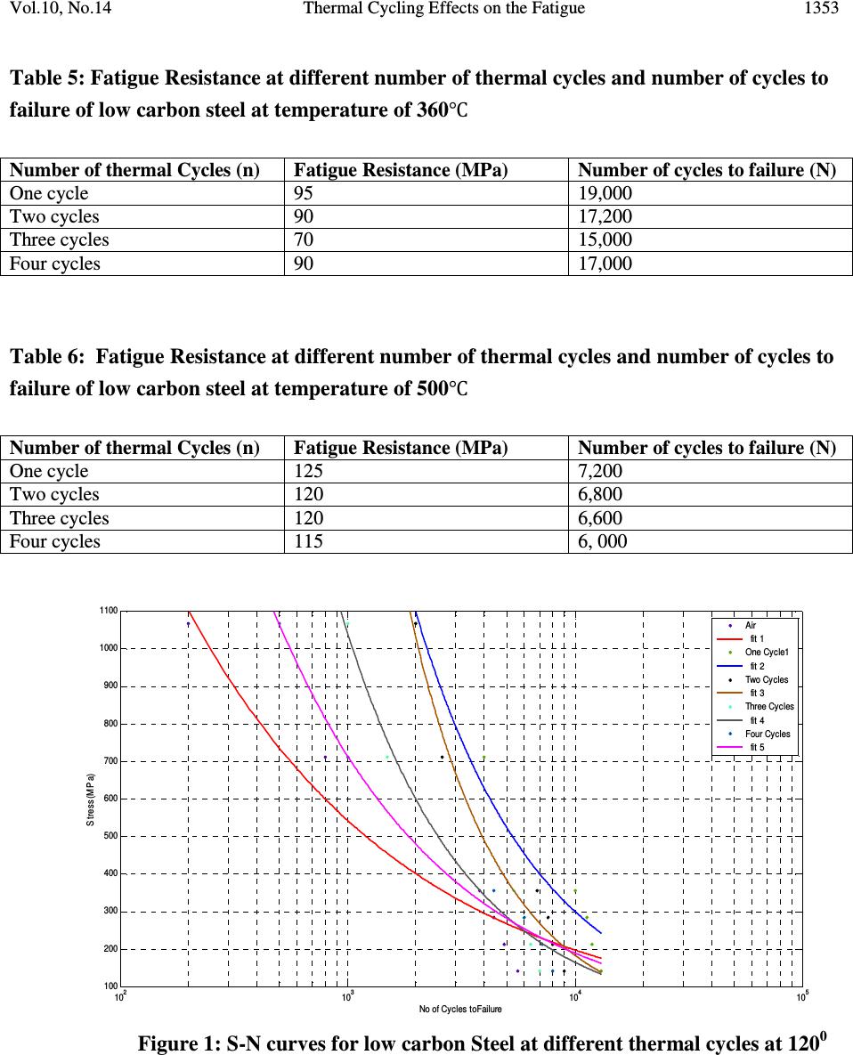 Vol.10, No.14 Thermal Cycling Effects on the Fatigue 1353 10 2 10 3 10 4 10 5 100 200 300 400 500 600 700 800 900 1000 1100 No of Cycles toFailure S tres s (M P a) Air fit 1 One Cycle1 fit 2 Two Cycles fit 3 Three Cycles fit 4 Four Cycles fit 5 Table 5: Fatigue Resistance at different number of thermal cycles and number of cycles to failure of low carbon steel at temperature of 360℃ Number of thermal Cycles (n) Fatigue Resistance (MPa) Number of cycles to failure (N) One cycle 95 19,000 Two cycles 90 17,200 Three cycles 70 15,000 Four cycles 90 17,000 Table 6: Fatigue Resistance at different number of thermal cycles and number of cycles to failure of low carbon steel at temperature of 500℃ Number of thermal Cycles (n) Fatigue Resistance (MPa) Number of cycles to failure (N) One cycle 125 7,200 Two cycles 120 6,800 Three cycles 120 6,600 Four cycles 115 6, 000 Figure 1: S-N curves for low carbon Steel at different thermal cycles at 120 0 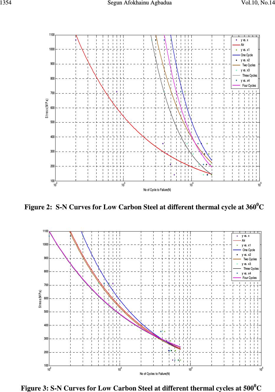 1354 Segun Afokhainu Agbadua Vol.10, No.14 10 2 10 3 10 4 10 5 100 200 300 400 500 600 700 800 900 1000 1100 No of Cycles to Failure(N) St r ess (MPa ) y vs. x Air y vs. x1 One Cycle y vs. x2 Two Cycles y vs. x3 Three Cycles y vs. x4 Four Cycles Figure 2: S-N Curves for Low Carbon Steel at different thermal cycle at 360 0 C Figure 3: S-N Curves for Low Carbon Steel at different thermal cycles at 500 0 C 10 2 10 3 10 4 10 5 100 200 300 400 500 600 700 800 900 1000 1100 No of Cycle to Failure(N) St re ss (MPa ) y vs. x Air y vs. x1 One Cycle y vs. x2 Two Cycles y vs. x3 Three Cycles y vs. x4 Four Cycles 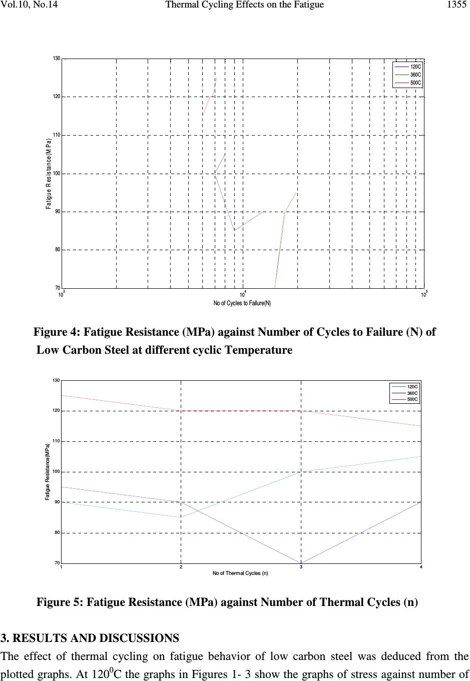 Vol.10, No.14 Thermal Cycling Effects on the Fatigue 1355 Figure 4: Fatigue Resistance (MPa) against Number of Cycles to Failure (N) of Low Carbon Steel at different cyclic Temperature Figure 5: Fatigue Resistance (MPa) against Number of Thermal Cycles (n) 3. RESULTS AND DISCUSSIONS The effect of thermal cycling on fatigue behavior of low carbon steel was deduced from the plotted graphs. At 120 0 C the graphs in Figures 1- 3 show the graphs of stress against number of 10 3 10 4 10 5 70 80 90 100 110 120 130 No of Cycles to Failure(N) Fatigue Resistance(M Pa) 120C 360C 500C 1 23 4 70 80 90 100 110 120 130 No of Thermal Cycles (n) Fatigue Resistance(MPa) 120C 360C 500C 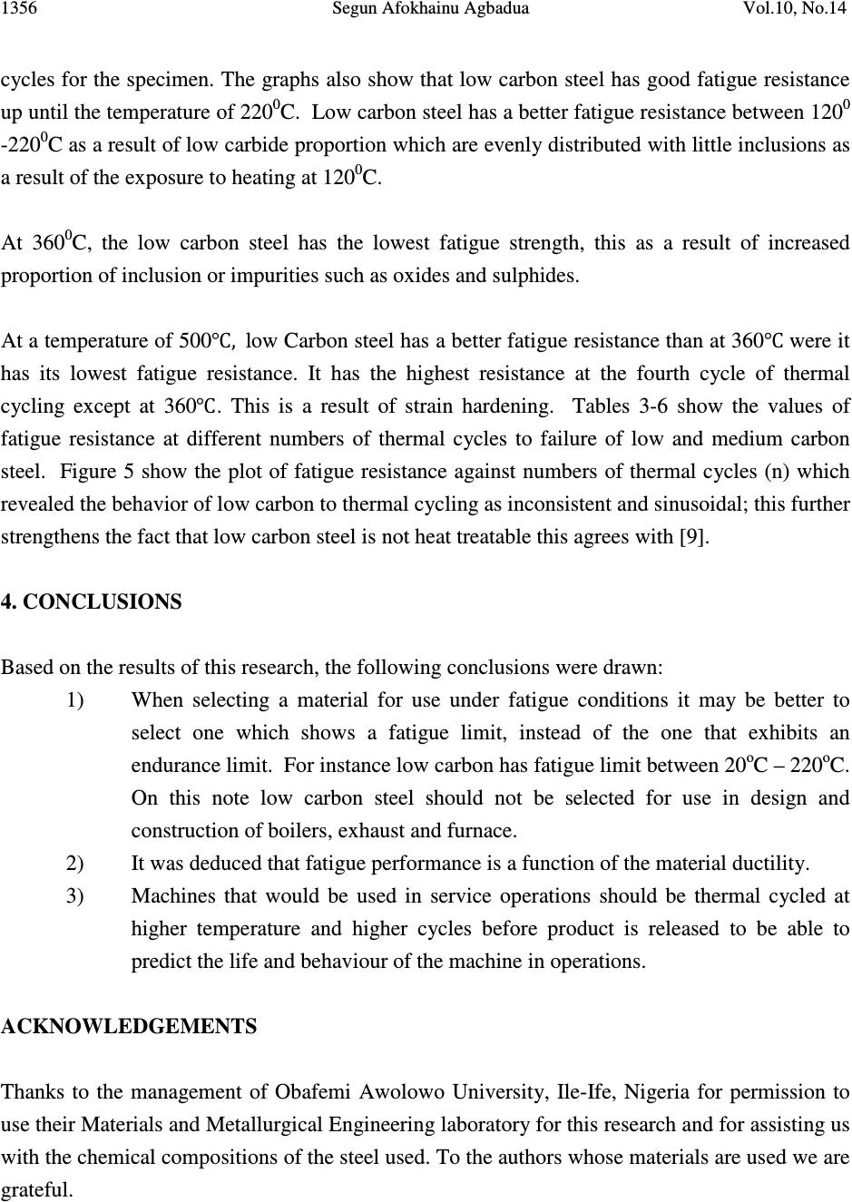 1356 Segun Afokhainu Agbadua Vol.10, No.14 cycles for the specimen. The graphs also show that low carbon steel has good fatigue resistance up until the temperature of 220 0 C. Low carbon steel has a better fatigue resistance between 120 0 -220 0 C as a result of low carbide proportion which are evenly distributed with little inclusions as a result of the exposure to heating at 120 0 C. At 360 0 C, the low carbon steel has the lowest fatigue strength, this as a result of increased proportion of inclusion or impurities such as oxides and sulphides. At a temperature of 500℃,low Carbon steel has a better fatigue resistance than at 360℃ were it has its lowest fatigue resistance. It has the highest resistance at the fourth cycle of thermal cycling except at 360℃. This is a result of strain hardening. Tables 3-6 show the values of fatigue resistance at different numbers of thermal cycles to failure of low and medium carbon steel. Figure 5 show the plot of fatigue resistance against numbers of thermal cycles (n) which revealed the behavior of low carbon to thermal cycling as inconsistent and sinusoidal; this further strengthens the fact that low carbon steel is not heat treatable this agrees with [9]. 4. CONCLUSIONS Based on the results of this research, the following conclusions were drawn: 1) When selecting a material for use under fatigue conditions it may be better to select one which shows a fatigue limit, instead of the one that exhibits an endurance limit. For instance low carbon has fatigue limit between 20 o C – 220 o C. On this note low carbon steel should not be selected for use in design and construction of boilers, exhaust and furnace. 2) It was deduced that fatigue performance is a function of the material ductility. 3) Machines that would be used in service operations should be thermal cycled at higher temperature and higher cycles before product is released to be able to predict the life and behaviour of the machine in operations. ACKNOWLEDGEMENTS Thanks to the management of Obafemi Awolowo University, Ile-Ife, Nigeria for permission to use their Materials and Metallurgical Engineering laboratory for this research and for assisting us with the chemical compositions of the steel used. To the authors whose materials are used we are grateful.  Vol.10, No.14 Thermal Cycling Effects on the Fatigue 1357 REFERENCES [1] Prokopenko, A. V., (1984). A method of evaluation of the life of a structure in programmed cyclic loading. pp 45-50, [2] Coffin, L.F., (1979). Fatigue in machines and structures- Power Generation, Fatigue and microstructure. pp 1-27. [3] Miner, M. A., Cumulative damage in fatigue transactions ASME, 67, 1945. [4] Basquin, O.H., (1910). The exponential law of endurance tests: American Society of Testing Materials, vol 10 pp 625-630. [5] McClintock, F. A and Hult, F. A, (1956) .In proceedings 9 th inter congress of applied mechanics, University of Brussels, Belgium, vol 8, pp 51 [6] Manson, S.S and Coffin, L.F., (1954). Behaviour of materials under conditions of thermal stress. [7] Coffin L, et al (1954) Apparatus for study of effects of cyclic thermal stresses on ductile metals. Transactions ASME vol 76: pp23-30. [8] Roehrig, K., (1978). Thermal fatigue of gray and ductile irons. AFS Trans. 86: 75–88 [9] Hearn, E. J., (1997). The mechanics of elastic and plastic deformation of solids and structural materials, pp 441-457& 491. |