 Journal of Minerals & Materials Characterization & Engineering, Vol. 10, No.13, pp.1213-1224, 2011 jmmce.org Printed in the USA. All rights reser ved 1213 Analysis of the Machining Characteristics on Surface Roughness of a Hybrid Aluminium Metal Matri x Com posite (Al6061-SiC-Al2O3) T.Sasimurugan 1*and K.Palanikumar 2 1Department of Mechanical and Production Engineering,Sathyabama University, Chennai-600 041, India. 2Department of Mechanical Engineering,Sri Sai Ram Institute of Technology , *E-mail: tsasimurugan@yahoo.com Abstract Aluminium metal matrix composites are finding increased applications in many areas. Adding of the third element to the metal matrix make the composite hybrid. This paper presents the study on the surface roughness characteristics of a hybrid aluminium metal matrix (Al6061-SiC- Al2O3) composites. The experimental studies were carried out on a lathe. The composites were prepared using the liquid metallurgy technique, in which 3, 6 and 9 wt % of particulates SiC and Al2O3 were dis per sed in the base matrix. The obtained cast composites wer e carefully machined. The characteristics that influence the surface roughness such as feed rate, depth of cut and cutting speed were stud ied, which made the analysis come to a conclusion that the surface roughness is increases with the increase of feed rate and it reduces the surface roughness with the increase of cutting speed. Keywor d s Hybrid Metal Matrix Composite, Machining, Cutting Speed, Depth of Cut, Feed Rate, Surface Roughness Nom enclatu re S Cutting speed in m/min F Feed rate in mm/rev D Depth of cut in mm Ra Average surface roughness in µm 1. INTRODUCTIO N Metal Matrix Composites are the newly engineered materials. Metal matrix composite consists of at least two constituent parts, of which one constituent part being a metal and the other part may be a different metal or another material, such as ceramic or organic compound. When at 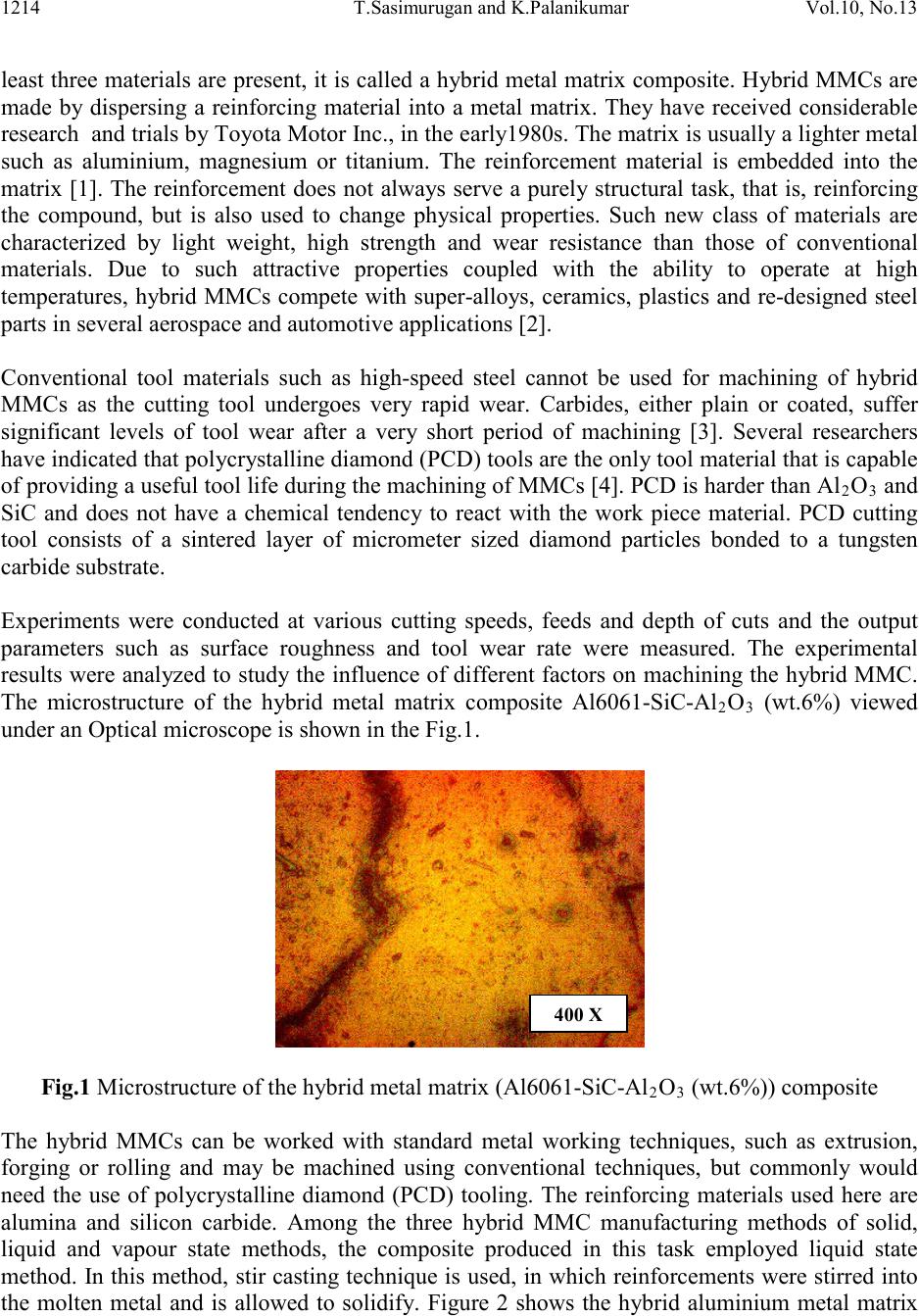 1214 T.Sasimur ugan and K.Palanikumar Vol.10, No.13 least t hree materi als are p resent, it i s called a hybrid metal matrix composite. Hybrid MMCs are made by dispersing a reinforcing material into a metal matrix. They have received considerable research and trials b y Toyota Motor Inc., in the earl y1980s. The matrix is usually a lighter metal such as aluminium, magnesium or titanium. The reinforcement material is embedded into the matrix [1]. The reinforcement does not always serve a purely structural task, that is, reinforcing the compound, but is also used to change physical properties. Such new class of materials are characterized by light weight, high strength and wear resistance than those of conventional materials. Due to such attractive properties coupled with the ability to operate at high temperat u res, hybrid MMCs compete with super-alloys, ceramics, plastics and re-designed steel parts in several aerospace and automotive applications [2]. Conventional tool materials such as high-speed steel cannot be used for machining of hybrid MMCs as the cutting tool undergoes very rapid wear. Carbides, either plain or coated, suffer significant levels of tool wear after a very short period of machining [3]. Several researchers have indicated that polycrystalline diamond (PCD) tools are the only tool material that is cap abl e of providing a useful tool life during the machining of MMCs [4]. PCD is harder than Al2O3 and SiC and does not have a chemical tendency to react with the work piece material. PCD cutting tool consists of a sintered layer of micrometer sized diamond particles bonded to a tungsten carbide substrate. Experiments were conducted at various cutting speeds, feeds and depth of cuts and the output parameters such as surface roughness and tool wear rate were measured. The experimental results were analyzed to study the influence of different factors on machining the hybrid MMC. The microstructure of the hybrid metal matrix composite Al6061-SiC-Al2O3 (wt.6%) viewed under an Optical microscope is shown in the Fig.1. Fig.1 Microstructure of the hybrid metal matrix (Al6061-SiC-Al2O3 (wt.6%)) composite The hybrid MMCs can be worked with standard metal working techniques, such as extrusion, forging or rolling and may be machined using conventional techniques, but commonly would need the use of polycrystalline diamond (PCD) tooling. The reinforcing materials used here are alumina and silicon carbide. Among the three hybrid MMC manufacturing methods of solid, liquid and vapour state methods, the composite produced in this task employed liquid state method. In this method, stir casting technique is used, in which reinforcements were stirred into the molten metal and is allowed to solidify. Figure 2 shows the hybrid aluminium metal matrix 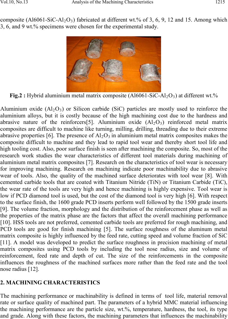 Vol.10, No.13 Analysis of the Machin ing Characteristics 1215 composite (Al6061-SiC-Al2O3) fabricated at di fferent wt.% of 3, 6, 9, 12 and 15. Among which 3, 6, and 9 wt.% specime ns were chosen for the experimental study. Fig.2 : Hybrid aluminium metal matrix composite (Al6061-SiC-Al2O3) at different wt.% Aluminium oxide (Al2O3) or Silicon carbide (SiC) particles are mostly used to reinforce the aluminium alloys, but it is costly because of the high machining cost due to the hardness and abrasive nature of the reinforcers[5]. Aluminium oxide (Al2O3) reinforced metal matrix composites are difficult to machine like turning, milling, drilling, threading due to their extreme abrasive properties [6]. The presenc e of Al2O3 in aluminium metal matrix composites makes the composite difficult to machine and they lead to rapid tool wear and thereby short tool life and high tooling cost. Also, poor surface finish is seen after machining the composite. So, most of the research work studies the wear characteristics of different tool materials during machining of aluminium metal matrix composites [7]. Res earch o n t he characteri s ti cs o f to ol wear i s n e cessary for improving machining. Research on machining indicate poor machinability due to abrasive wear of tools. Also, the quality of the machined surface deteriorates with tool wear [8]. With cemented carbide tools that are coated with Titanium Nitride (TiN) or Titanium Carbide (TiC), the wear rate of the tools are very high and hence machining is highly expensive. Tool wear is low if PCD diamond tool is used, but the cost of the diamond tool is very high [6]. Wit h respect to the surface finish, the 1600 grade PCD inserts perform well followed by the 1500 grade inserts [9]. The volume fraction, morphology and the distribution of the reinforcement phase as well as the properties of the matrix phase are the factors that affect the overall machining performance [10]. HSS tools are not preferred, cemented carbide tools are preferred for rough machining, and PCD tools are good for finish machining [5]. The surface roughness of the aluminum metal matrix composite is highly influenced by the feed rate, cutting speed and volume fraction of SiC [11]. A model was developed to predict the surface roughness in precision machining of metal matrix composites using PCD tools by including the tool nose radius, size and volume of reinforcement, feed rate and depth of cut. The size of the reinforcements in the composite influences the roughness of the machined surfaces more rather than the feed rate and the tool nose radius [12]. 2. MACHINING CHARACTERISTICS The machining performance or machinability is defined in terms of tool life, material removal rate or surface quality of machined part. The parameters of a hybrid MMC material influencing the machining performance are the particle size, wt.%, temperature, hardness, the tool, its type and grade. Along with these factors, the machining paramet ers that influ ences the machinability 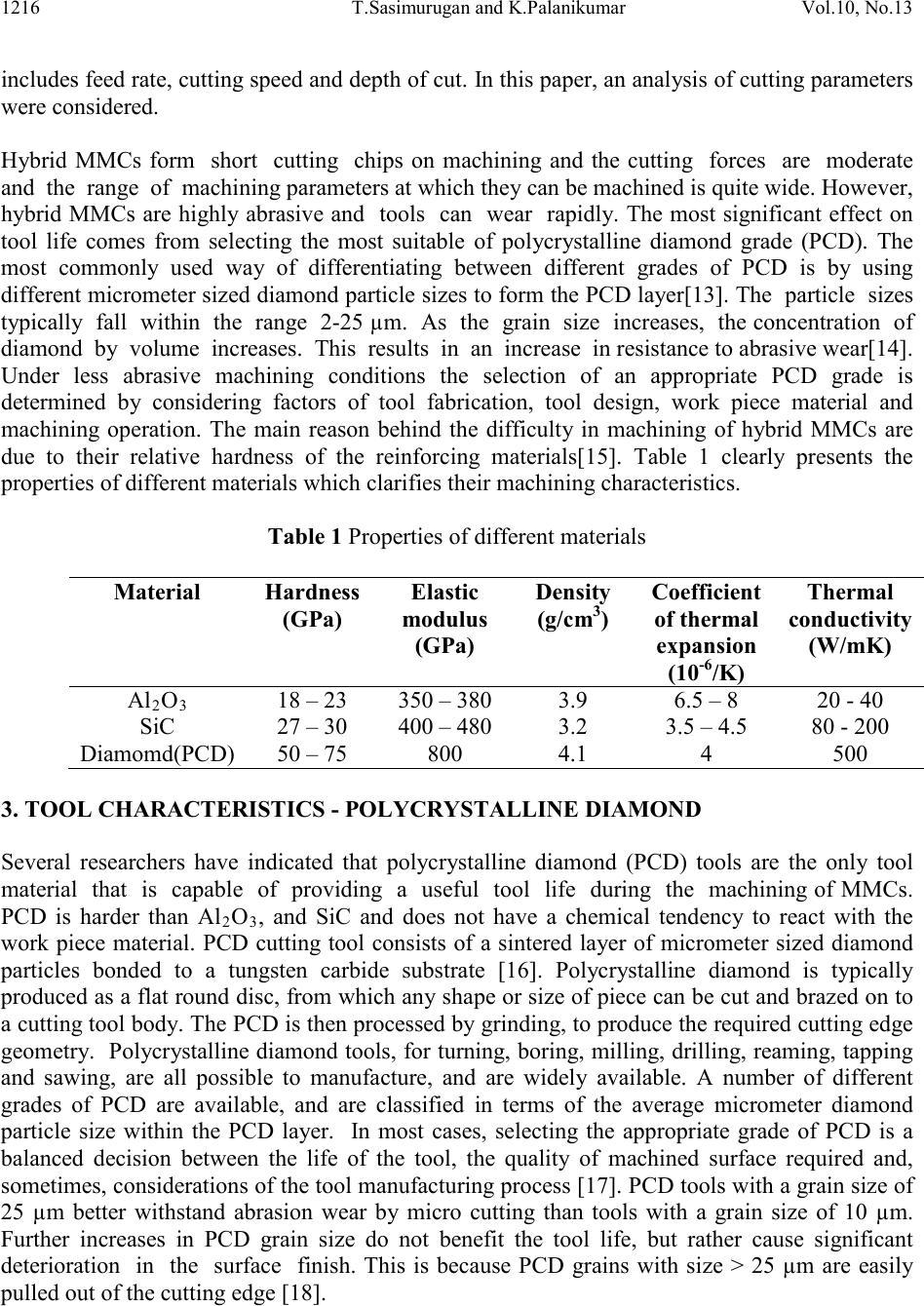 1216 T.Sasimur ugan and K.Palanikumar Vol.10, No.13 includ es feed rat e, cutting speed and depth of cut. In this paper, an analysis of cutting parameters were consi dered . Hybrid MMCs form short cutting chips on machining and the cutting forces are moderate and the range of machining parameters at which they can be machined is quite wide. However, hybrid MMCs are highly abrasive and tools can wear rapidly. The most significant effect on tool life comes from selecting the most suitable of polycrystalline diamond grade (PCD). The most commonly used way of differentiating between different grades of PCD is by using different micrometer sized diamond particle sizes to form the PCD layer[13]. The parti cle sizes t yp ic al l y fall within the ran ge 2 -25 µm. A s t he grain size increases , the concent ration o f diamond by volume increases. This results in an increase in resistance to abrasive wear[14]. Under less abrasive machining conditions the selection of an appropriate PCD grade is determined by considering factors of tool fabrication, tool design, work piece material and machining operation. The main reason behind the difficulty in machining of hybrid MMCs are due to their relative hardness of the reinforcing materials[15]. Table 1 clearly presents the properties of different materials which clarifies their machining characteristics. Table 1 Properties of different materials (G Pa ) modulus (G Pa ) (g/cm3) of thermal expansion -6 conductivity (W/mK) 3. TOOL CHARACTERISTICS - POLYCRYSTALLINE DIAMOND Several researchers have indicated that polycrystalline diamond (PCD) tools are the only tool material that is capable of providing a useful tool life during the machining of MMCs. PCD is harder than Al2O3, and SiC and does not have a chemical tendency to react with the work piece material. PCD cutting tool consists of a sintered layer of micrometer sized diamond particles bonded to a tungsten carbide substrate [16]. Polycrystalline diamond is typically produced as a flat round disc, from which any shape or size of piece can be cut and brazed on to a cutting tool body. The PCD is then processed by grinding, to produce the required cutting edge geometry. Polycrystalline diamond tools, for turning, boring, milling, drilling, reaming, tapping and sawing, are all possible to manufacture, and are widely available. A number of different grades of PCD are available, and are classified in terms of the average micrometer diamond particle size within the PCD layer. In most cases, selecting the appropriate grade of PCD is a balanced decision between the life of the tool, the quality of machined surface required and, sometimes, considerations of the tool manufacturing process [17]. PCD tools with a grain size of 25 µm better withstand abrasion wear by micro cutting than tools with a grain size of 10 µm. Further increases in PCD grain size do not benefit the tool life, but rather cause significant deterioration in the surface finish. This is because PCD grains with size > 25 µm are easily pulled out of the cutting edge [18].  Vol.10, No.13 Analysis of the Machin ing Characteristics 1217 To study the difficulties in machining of hybrid MMCs, previous investigations on the machinability of hybrid MMCs have covered the effects of machining parameters and the properties of hybrid MMCs on the tool wear and the mechanism of the tool wear. M a ny sc holars have studied and investigated various factors affecting the machinability of hybrid MMCs and had derived different conclusions. Tomac and Tonnensen [5] studied the effect of cutting speed when turning Al-SiC MMCs with polycrystalline diamond (PCD) and coated tungsten carbide tools and found that high cutting speeds shorten tool life by causing excessive flank wear. They invest igated the effect of feed r ate an d foun d t hat high feed rat e set tin g can reduc e the tool wear. This is because, at higher feed rates the temperature of the cutting zone increases. This leads to the softening of the metallic matrix enabling easier removal of the embedded SiC particle in the work piece. It was repo rted b y Lane [ 7] that the tool life of the PCD cutting tool was found to be inversely proportional to the depth of cut. Various studies have proved that PCD is the ideal cutting tool material for machining hybrid aluminium matrix MMCs with high efficiency. PCD tools showed better wear resistance and produced better surface finish than carbide or alu mina tools. This was due to the hi gher hardness of the diamond tools and the lower affinity with the MMC material [19]. The grain size of the cutting tools has significant influence on the tool wear during machining of MMC. While a tool with coarse grain has a high abrasion resistance required for increased performance, increasing the size of the grains can result in drop in the rupture strength, which also i nfluences o veral l to ol performance. The present work deals with the machining characterization of hybrid MMC using PCD cutting tool, and the resultant surface roughness and tool wear associated with machinability. Aluminium oxide (Al 2O3) possess low coefficient of thermal expansion in the order of 6.5-8x10- 6/K and hardness of 18-23 GPa. Addition of Al2O3 particles imparts dimensional and thermal stability, improves hardness, wear resistance, stiffness and reduces the density of the matrix material [20]. Here Al6061 was selected as the matrix material to which SiC and Al2O3 were added as the disperoids. 4. EXPERIME NTAL PROCE DURE 4.1 Composite Preparation 4.1.1 Liquid metallurgy – Stir Casting Method A liquid metallurgy method was used to produce cast composites with better wettability and particle distribution. The Al6061 alloy, which was in the form of bars, was cut into small pieces and melted in a graphite crucible. The chemical composition of Al6061 by weight percentage is shown in Table 2. The preh eated calcul ated quan tity of mat rix materi al was fed into the cruci ble and mix ed evenly using the stirrer operated by a motor. The temp erature was raised above the liquidus t emperature of the aluminium alloy and then reduced slowly below liquidus temperature of the matrix material such that the melt was kept between the solidus and liquidus temperature (semi liquid state). The next step is addition of the pre-heated blended mixtures of SiC and aluminium oxide 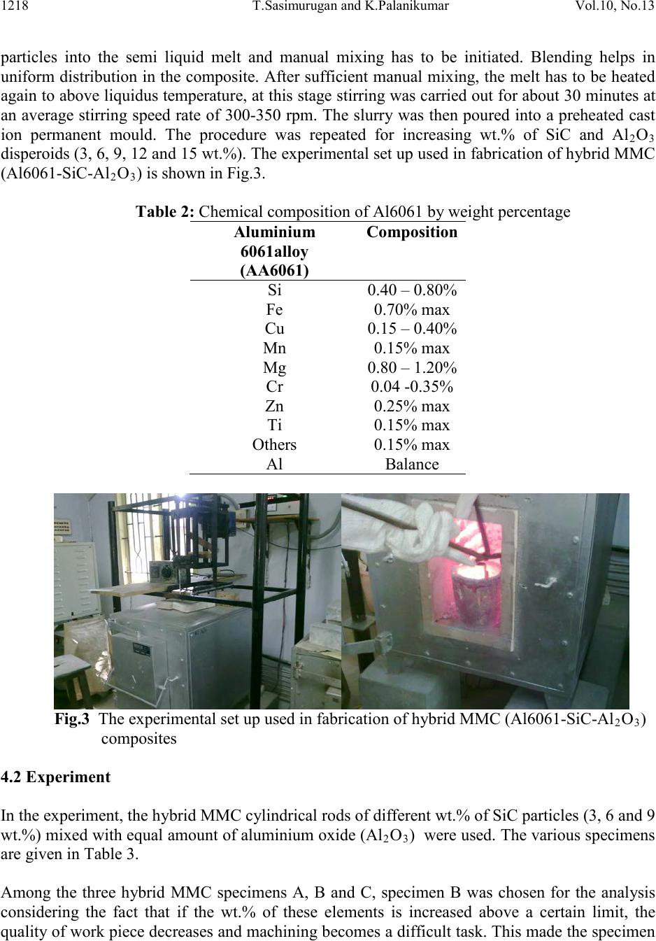 1218 T.Sasimur ugan and K.Palanikumar Vol.10, No.13 particles into the semi liquid melt and manual mixing has to be initiated. Blending helps in uniform distribution in the composite. After sufficient manual mixing, the melt has to be heated again to above liquidus temperature, at this stage stirring was carried out for about 30 minutes at an average stirring speed rate of 300-350 rpm. The slurry was then poured into a preheated cast ion permanent mould. The procedure was repeated for increasing wt.% of SiC and Al2O3 disperoids (3, 6, 9, 12 an d 15 wt.%). The experimental set up used in fabrication of hybrid MMC (Al6061-SiC-Al2O3) is shown in Fig.3. Table 2: Chemical composition of Al6061 by weight percentage 6061alloy Fig.3 The experimental set up used in fabrication of hybrid MMC (Al6061-SiC-Al2O3) composites 4.2 Experiment In the experiment, the hybrid MMC cylindrical rods of different wt.% of SiC particles (3, 6 and 9 wt.%) mixed with equal amount of aluminium oxi de (Al2O3) were used. The various specimens are given in Table 3. Among the three hybrid MMC specimens A, B and C, specimen B was chosen for the analysis considering the fact that if the wt.% of these elements is increased above a certain limit, the qualit y of work pi ece de creas es and machi nin g beco mes a di fficu lt t ask. Th is mad e the sp ecimen 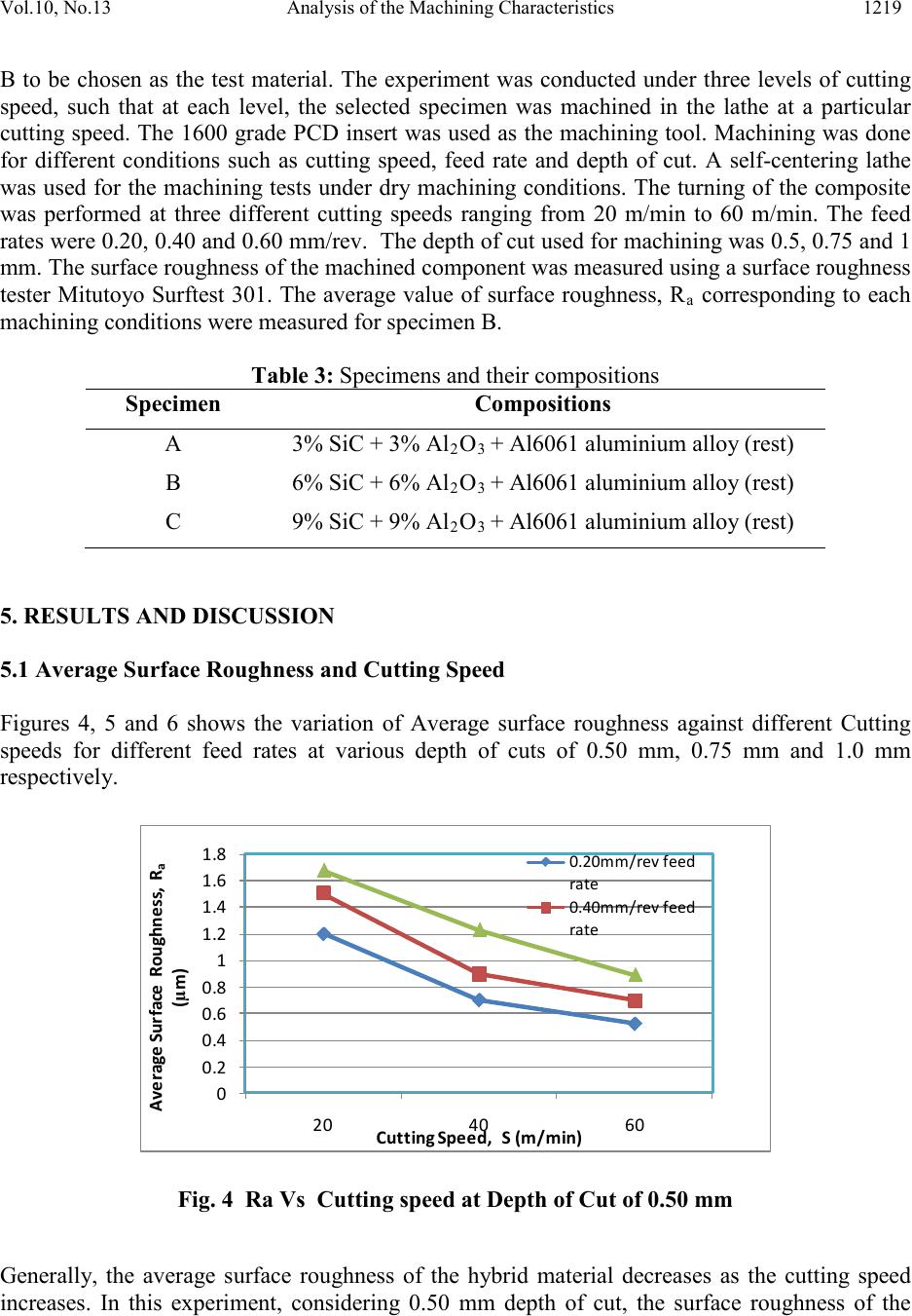 Vol.10, No.13 Analysis of the Machin ing Characteristics 1219 B to be chosen as the test material. The experiment was conducted under three levels of cutting speed, such that at each level, the selected specimen was machined in the lathe at a particular cutting speed. The 1600 grade PCD insert was used as the machining tool. Machining was done for different conditions such as cutting speed, feed rate and depth of cut. A self-centering lathe was used for the machining tests under dry machining conditions. The turning of the composite was performed at three different cutting speeds ranging from 20 m/min to 60 m/min. The feed rates were 0.20, 0.40 and 0.60 mm/rev. The depth of cut used for machining was 0.5, 0.75 and 1 mm. The surface roughness of the machined component was measured using a surface roughness tester Mitutoyo Surftest 301. The average value of surface roughness, R a corresponding to each machining conditions were measured for specimen B. Table 3: Specimens and their compositions 2 3 + Al6061 aluminium alloy (rest) 2 3 + Al6061 aluminium alloy (rest) 2 3 + Al6061 aluminium alloy (rest) 5. RESULTS AND DISCUSSION 5.1 Average Surface Roughness and Cutting Speed Figures 4, 5 and 6 shows the variation of Average surface roughness against different Cutting speeds for different feed rates at various depth of cuts of 0.50 mm, 0.75 mm and 1.0 mm respectively. 0 0.2 0 .4 0.6 0 .8 1 1 .2 1.4 1.6 1.8 Average Surface Roughness, R a (µm) Fig . 4 Ra Vs Cutting speed at Depth of Cut of 0.50 mm Generally, the average surface roughness of the hybrid material decreases as the cutting speed increases. In this experiment, considering 0.50 mm depth of cut, the surface roughness of the 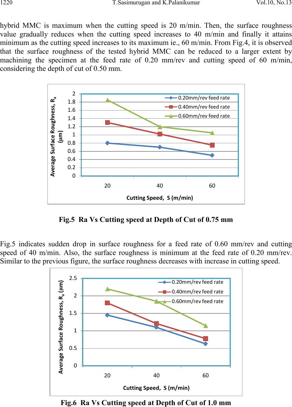 1220 T.Sasimur ugan and K.Palanikumar Vol.10, No.13 hybrid MMC is maximum when the cutting speed is 20 m/min. Then, the surface roughness value gradually reduces when the cutting speed increases to 40 m/min and finally it attains minimum as the cutting speed increases to its maximum ie., 60 m/min. From Fig.4, it is observed that the surface roughness of the tested hybrid MMC can be reduced to a larger extent by machining the specimen at the feed rate of 0.20 mm/rev and cutting speed of 60 m/min, considering the depth of cut of 0.50 mm. 0 0.2 0.4 0.6 0.8 1 1.2 1.4 1.6 1.8 2 Average Surface Roughness, R a (µm) Fig.5 Ra Vs Cutting speed at Depth of Cut of 0.75 mm Fig.5 indicates sudden drop in surface roughness for a feed rate of 0.60 mm/rev and cutting speed of 40 m/min. Also, the surface roughness is minimum at the feed rate of 0.20 mm/rev. Similar to the previous figure, the surface roughness decreases with increase in cutting speed. Average Surface Roughness, R a (µm) Fig.6 Ra Vs Cutting speed at Depth of Cut of 1.0 mm 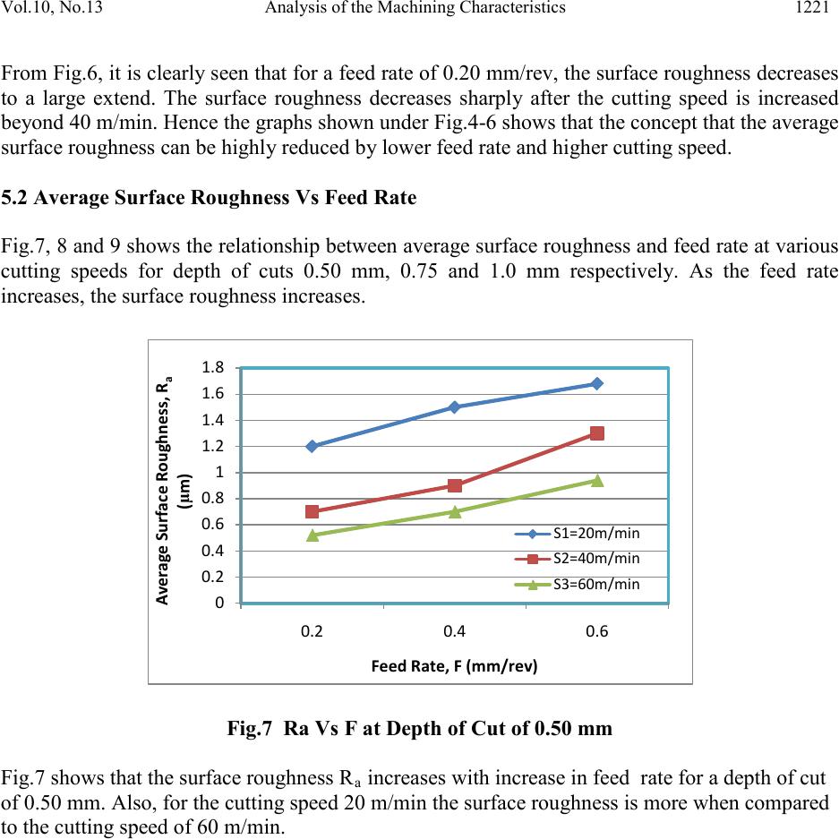 Vol.10, No.13 Analysis of the Machin ing Characteristics 1221 From Fig.6, it i s clearl y seen that fo r a feed rate o f 0.2 0 mm/rev , the su rface ro ughnes s decr eases to a large extend. The surface roughness decreases sharply after the cutting speed is increased beyond 40 m/min. Hence the graphs shown under Fig.4-6 shows that the concept that the average surface roughness can be highly reduced by lower feed rate and higher cutting speed. 5.2 Average Surface Roughness Vs Feed Rate Fig.7, 8 and 9 shows the relationship between average surface roughness and feed r ate at various cutting speeds for depth of cuts 0.50 mm, 0.75 and 1.0 mm respectively. As the feed rate increases, the surface roughness increases. 0 0.2 0.4 0.6 0.8 1 1.2 1.4 1.6 1.8 Average Surface Roughness, R a (µm) Fig.7 Ra Vs F at Depth of Cut of 0.50 mm Fig.7 shows that the surface roughness Ra increases with increase in feed rate for a depth of cut of 0.50 mm. Also, for the cutting speed 20 m/min the surface roughness is more when compared to the cutting speed of 60 m/min. 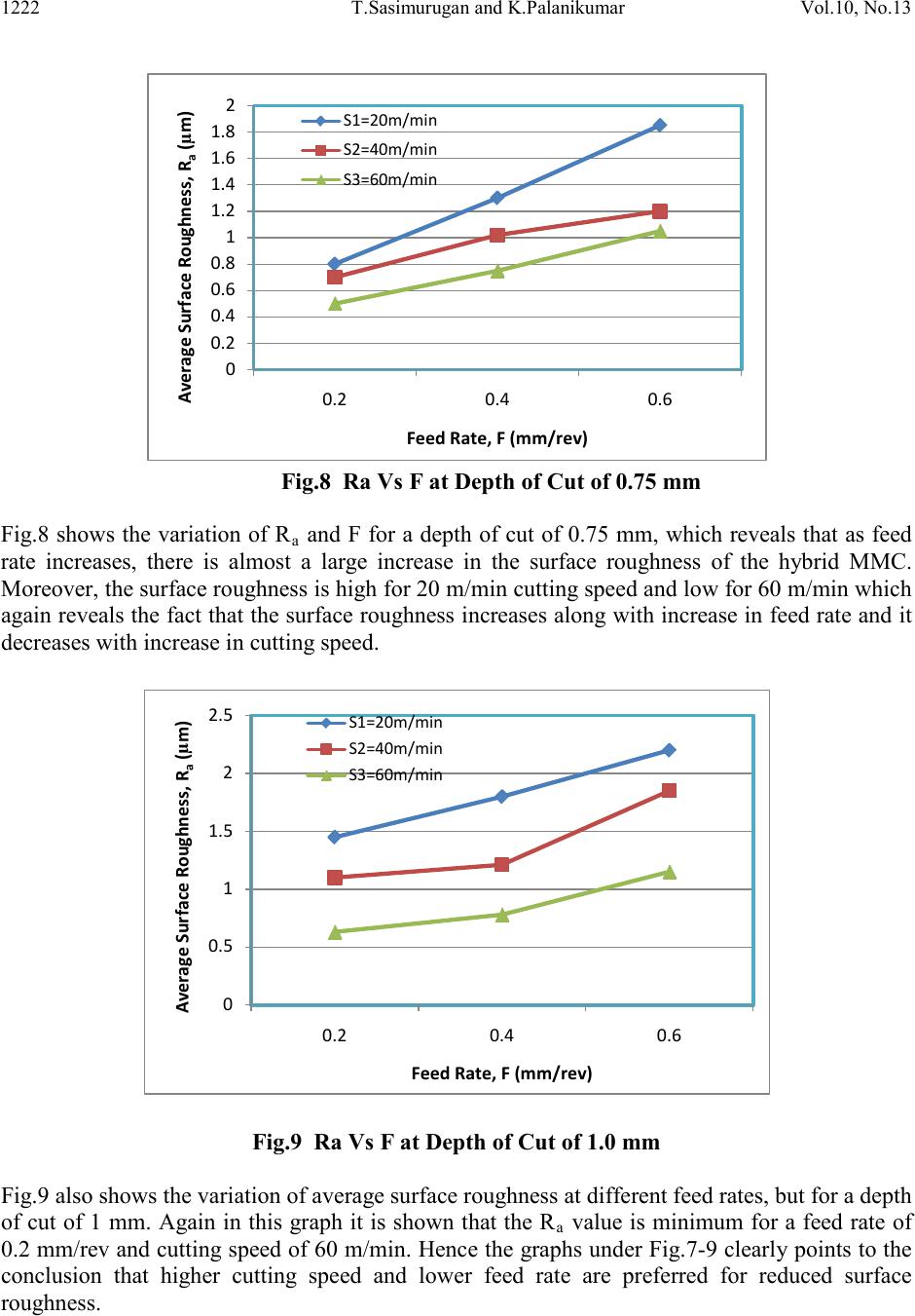 1222 T.Sasimur ugan and K.Palanikumar Vol.10, No.13 0 0.2 0.4 0.6 0.8 1 1.2 1.4 1.6 1.8 2 Average Surface Roughness, R a (µm) Fig.8 Ra Vs F at Depth of Cut of 0.75 mm Fig.8 shows the variation of R a and F for a depth of cut of 0.75 mm, which reveals that as feed rate increases, there is almost a large increase in the surface roughness of the hybrid MMC. Moreover, the surface roughness is high for 20 m/min cutting speed and low for 60 m/min which again r eveals the f act that the surface roughness i ncreases al ong with increase in feed rate and it decreases with increase in cutting speed. Average Surface Roughness, Ra(µm) Fig.9 Ra Vs F at Depth of Cut of 1.0 mm Fig.9 also shows the variation of average surface roughness at different feed rates, but for a depth of cut of 1 mm. Again in this graph it is shown that the R a value is minimum for a feed rate of 0.2 mm/rev and cutting speed of 60 m/min. Hence the graphs under Fig.7-9 clearly points to the conclusion that higher cutting speed and lower feed rate are preferred for reduced surface roughness. 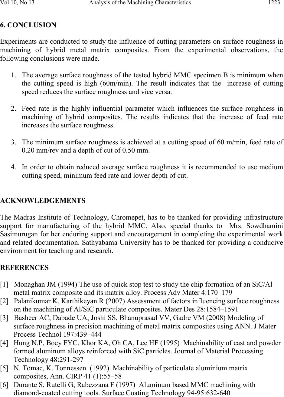 Vol.10, No.13 Analysis of the Machin ing Characteristics 1223 6. CONCLUSIO N Experiments are conducted to study the influence of cutting parameters on surface roughness in machining of hybrid metal matrix composites. From the experimental observations, the following conclusions were made. 1. The average surface roughness of the tested h ybrid MMC specimen B is minimum when the cutting speed is high (60m/min). The result indicates that the increase of cutting speed reduces the surface roughness and vice versa. 2. Feed rate is the highly influential parameter which influences the surface roughness in machining of hybrid composites. The results indicates that the increase of feed rate increases the surface roughness. 3. The minimum surface roughness is achieved at a cutting speed of 60 m/min, feed rate of 0.20 mm/rev and a depth of cut of 0.50 mm. 4. In order to obtain reduced average surface roughness it is recommended to use medium cutting speed, minimum feed rate and lower depth of cut. ACKNOWLEDGEMENTS The Madras Institute of Technology, Chromepet, has to be thanked for providing infrastructure support for manufacturing of the hybrid MMC. Also, special thanks to Mrs. Sowdhamini Sasimurugan for her enduring support and encouragement in completing the experimental work and related documentation. Sathyabama University has to be thanked for providing a conducive environment for teaching and research. REFERENCES [1] Monaghan JM (1994) The use of quick stop test to study the chip formation of an SiC/Al metal matrix composite and its matrix alloy. Process Adv Mater 4:170–179 [2] Palanikumar K, Karthikeyan R (2007) Assessment of factors influencing surface roughness on the machining of Al/SiC particulate composites. Mater Des 28:1584–1591 [3] Basheer AC, Dabade UA, Joshi SS, Bhanuprasad VV, Gadre VM (2008) Modeling of surface roughness in precision machining of metal matrix composites using ANN. J Mater Process Technol 197:439–444 [4] Hung N.P, Boey FYC, Khor KA, Oh CA, Lee HF (1995) Machinability of cast and powder formed aluminum alloys reinforced with SiC particles. Journal of Material Processing Technology 48:291-297 [5] N. Tomac, K. Tonnessen (1992) Machinability of particulate aluminium matrix composites, Ann. CIRP 41 (1):55–58 [6] Durante S, Rutelli G, Rabezzana F (1997) Aluminum based MMC machining with diamond-coated cutting tools. Surface Coating Technology 94-95:632-640  1224 T.Sasimur ugan and K.Palanikumar Vol.10, No.13 [7] Lane CT (1992) Machinability of Al composites as a function of matrix alloy and heat treatment, in: Proceedings of the Machining of Composites Materials Symposium. ASM Materials Week, Chicago, IL, pp 3–15 [8] Sahin Y, Kok M, Celik H (2002) Tool wear and surface roughness of Al2O3 particle- reinforced aluminium alloy composites. J Mater Process Technol 128:280–291 [9] Finn M, Srivastava A (1996). Machining of advanced and engineered materials, in: Proceedings of the CSME Symposium. McMaster University, pp. 616-623. [10] El-Gallab M, Sklad M (1998) Machining of Al/SiCp metal matrix composites. Part I, Tool performance. J Mater Process Technol 83:151–158 [11] Yanming Q, Zehna Z (2000) Tool wear and its mechanism for cutting SiCp reinforced Al matrix composites. J Mater Process Technol 100:194–199 [12] Joshi SS, Ramakrishnan N, Ramakrishnan P (1999) Analysis of chip breaking during orthogonal machining of Al/SiCp composites. J Mater Process Technol 88:90–96 [13] Lin JT, Bhattacharya D, Lane CT (1995) Machinability of a silicon carbide reinforced aluminium metal matrix composite. Wear 181:883–888 [14] Chandrasekaran H, Johansson JO (1997) Influence of processing conditions and reinforcement on the surface quality of finish machined aluminium alloy matrix composites. Ann CIRP 46(1):493–496 [15] Pendse DM, Joshi SS (2004) Modeling and optimization of machining process in discontinuously reinforced aluminum matrix composites. Int J Mach Sci Technol 8(1):85– 102 [16] Metin Kok (2011) Modelling the effect of surface roughness factors in the machining of 2024 Al/Al2O3 particle composites based on orthogonal arrays. International Journal of Advanced Manufacturing Technology 170-010-3134 [17] N.Muthukrishnan, M.Murugan, K.Prahlada Rao (2007) An Investigation on the machinability of Al-SiC metal matrix composites using PCD inserts 38:447-454 [18] Lane C (1992), The effect of different reinforcements on PCD tool life for aluminium composites. Proceedings of the machining of Composites Materials Symposium. ASM Material week, Chicago, IL 1-5:17-27. [19] A.R. Boccaccini, G. Ondracek, P. Mazilu, D. Windelberg, J. Mech.Behav. Mater. 4 (1993) 119. [20] V.V. Ganesh, M. Gupta, Mater. Sci. Technol. 17 (2001) 1465.
|