Journal of Minerals & Materials Characterization & Engineering, Vol. 10, No.13, pp.1205-1212, 2011
jmmce.org Printed in the USA. All rights reserved
1205
Development and C haracte r iz at ion of Fe-Based Friction Material Made
by Hot Powd er Prefor m Forging for Low D uty Ap plications
A.A.S. Ghazi*, K. Chandra, P.S. Misra
Department of Metallurgical and Materials Engineering, Indian Institute of Technology
Roorkee, India.
*Corresponding Author: aas_ghazi@yahoo.com
ABSTRACT:
This present paper investigates the friction and wear properties of friction material
developed by ‘Hot Powder Preform Forging’ technique. The conventional technique to
manufacture Metallo-ceramic brake pads was successfully and economically tried to replace
the above process. Compacting and sintering technology suffers from certain major
limitations such as inadequate joining of friction element with backing plate, poor density
levels achieved in friction element owing to limited application of pressure during
compacting, poor thermal conductivity due to high levels of porosity in the product, poor
strength due to segregation of the impurities along prior particle boundaries (PPB’s) and,
wide variations in final characteristics due to large number of variables involved. In contrast
to these limitations, the present technique can offer brake pads of much simpler chemistry but
with improved performance on account of simultaneous application of pressure and
temperature and with better control of variables. Fade and recovery studies were carried out
on a Krauss machine tester following the Economic Commission for Europe Regulation for
replacement brake linings (ECE R-90). μfade, μrecovery, μperformance, % age fade , % age
recovery & temperature rise lie within the range for friction materials used for low duty
applications. The mechanical properties of these materials were characterized using ASTM
standards.
Keywords: Friction material; Preform forging; B rake pads; Fade.
1. INTRODUCTIO N
Brakes are one of the most important safety and performance components in automobiles.
Most of the brake linings used in American cars are based on a metal fiber reinforced
phenolic resin matrix and are called semi metallic. There are, however, also other types of
lining materials, categorized into metallic, organic and carbon based. Most of the brake
linings are typically a composite of a number of different materials. Sometimes, up to 20 or
25 different constituents are used. These ingredients are categorized into four broad classes:
binders, structural materials, fillers and frictional additives/modifiers. The binders bind
together rest of the ingredients, structural materials provide the structural reinforcement to the
1206 A.A.S. Ghazi, K. Chandra, P.S. Misra Vol.10, No.13
composite matrix, fillers make up the volume of the brake lining, while keeping the costs
down, and friction modifiers stabilize the coefficient of friction [1].
A limited number of studies investigating the compositional effect are available in the
literature and a complete analysis concerning all the ingredients in a friction material is
seldom found. The limited information about ingredients used in the friction material and
their effects on the friction characteristics is partly ascribed to proprietary reasons [2-6]. The
development of new pad materials is a complicated matter as the components interact and
synergetic effects that are hard to disentangle arise [7].
Compacting and sintering technology [8] is one such technology through which Metallo-
ceramic brake pads are currently being made. However, it suffers from certain major
limitations such as inadequate joining of friction element with backing plate, poor density
levels achieved in friction element owing to limited application of pressure during
compacting, poor thermal conductivity due to high levels of porosity in the product, poor
strength due to segregation of the impurities along prior particle boundaries (PPB’s),
anisotropy in the strength of the product owing to preferred direction due of pressing, and,
wide variations in final characteristics due to large number of variables involved. Besides
above, cost of raw material and consumables along with heavy capital equipment makes this
technique costly and only large scale production is possible where these costs are distributed
in the large volume of production. In contrast to these limitations, the present technique can
offer brake pads of much simpler chemistry but with improved performance on account of
simultaneous application of pressure and temperature and with better control of variables.
The technique does not involve any custom built equipment and is also likely to become
economical even with small volume production [9].
2. EXPERIMENTAL
Friction materials investigated in this stud y are iron-based met al m at rix com po si tes whi ch ar e
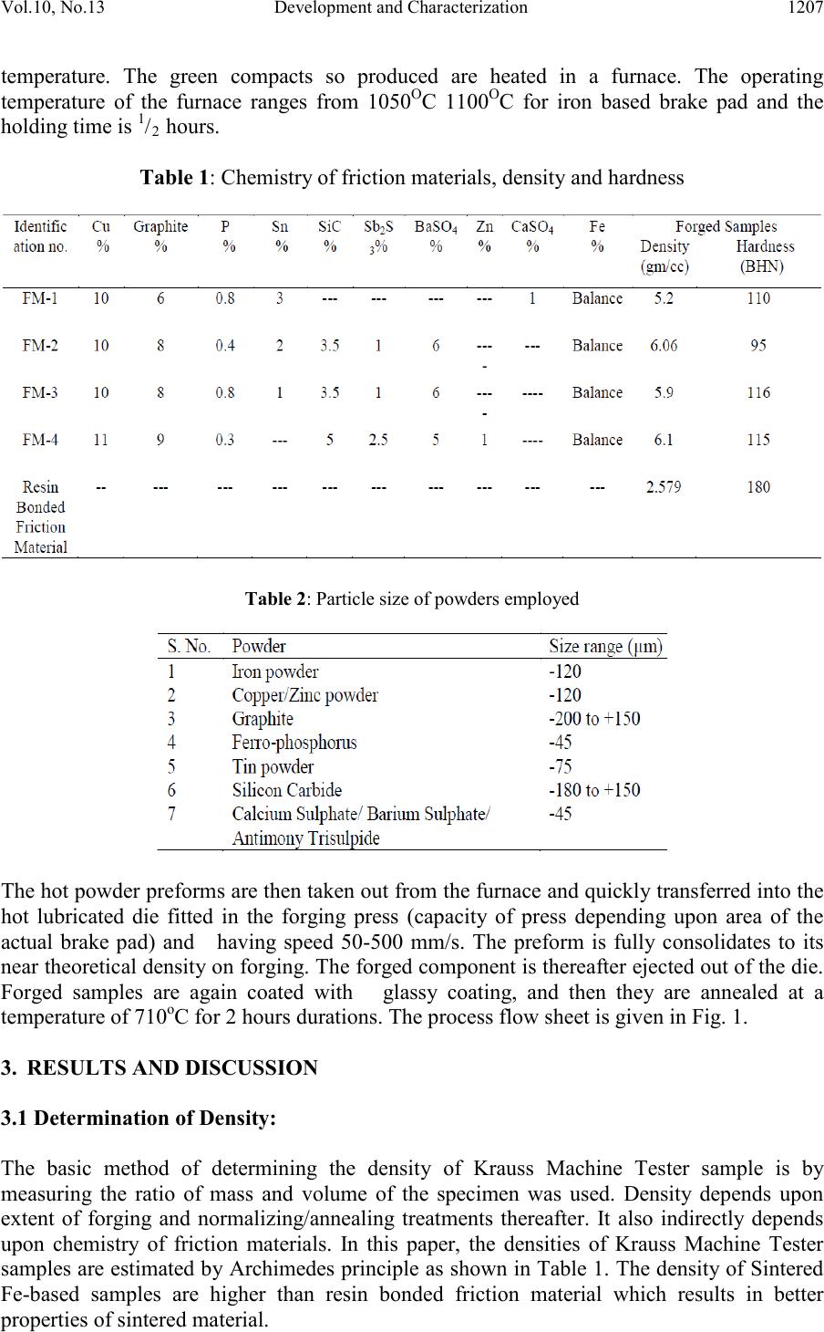
produced by ‘Hot Powder Preform Forging’ technique. The compositions are given in Table
1. Samples of the dimension (25 mm × 50 mm ×10 mm) for testing on Krauss Machine
Tester ar e pr ep ared as follows whi ch i s used to check th e su it abi li ty of fri ct i on mat eri als to be
used for low and moderate duty applications. The particle size of the raw materials chosen in
the present investigation is given in Table 2. Powder mixtures for friction layer as per the
chemistry are prepared. Firstly, SiC powder is mechanically alloyed with sulphide / sulphate
powders, graphite powder (fine - 1/3rd of the total % age), etc. This will ensure coating of soft
powders on hard SiC powder. The attritor speed ranges from 150 rpm to 200 rpm, ball to
charge ratio is 5:1 and th e duration is 2 hrs (Powder Mix -1). Then, entire amount of iron and
other powders such as Cu, Zn, etc as per the chosen chemistry is mechanically alloyed with
graphite powder (flake 2/3rd of the total % age) in the attritor with the same operating
parameters (Powder Mix-2). Lastly, the two powder mixtures (Powder Mix-1 and Powder
Mix-2) are then mechanically mixed with each other in a ball mill (180 rpm) for 2 hrs.
Powder compaction is done in a suitably designed die in accordance with the given shape of
the Krauss Machine Tester sample by pressing in a Screw forging press with the help of
upper and lower punches at a pressure of 750 MPa. The compacts are then ejected out of the
die. The die is suitably lubricated employing graphite in the suspension of methyl
alcohol/ethyl alcohol/acetone for easy ejection without cracking of green compact. Green
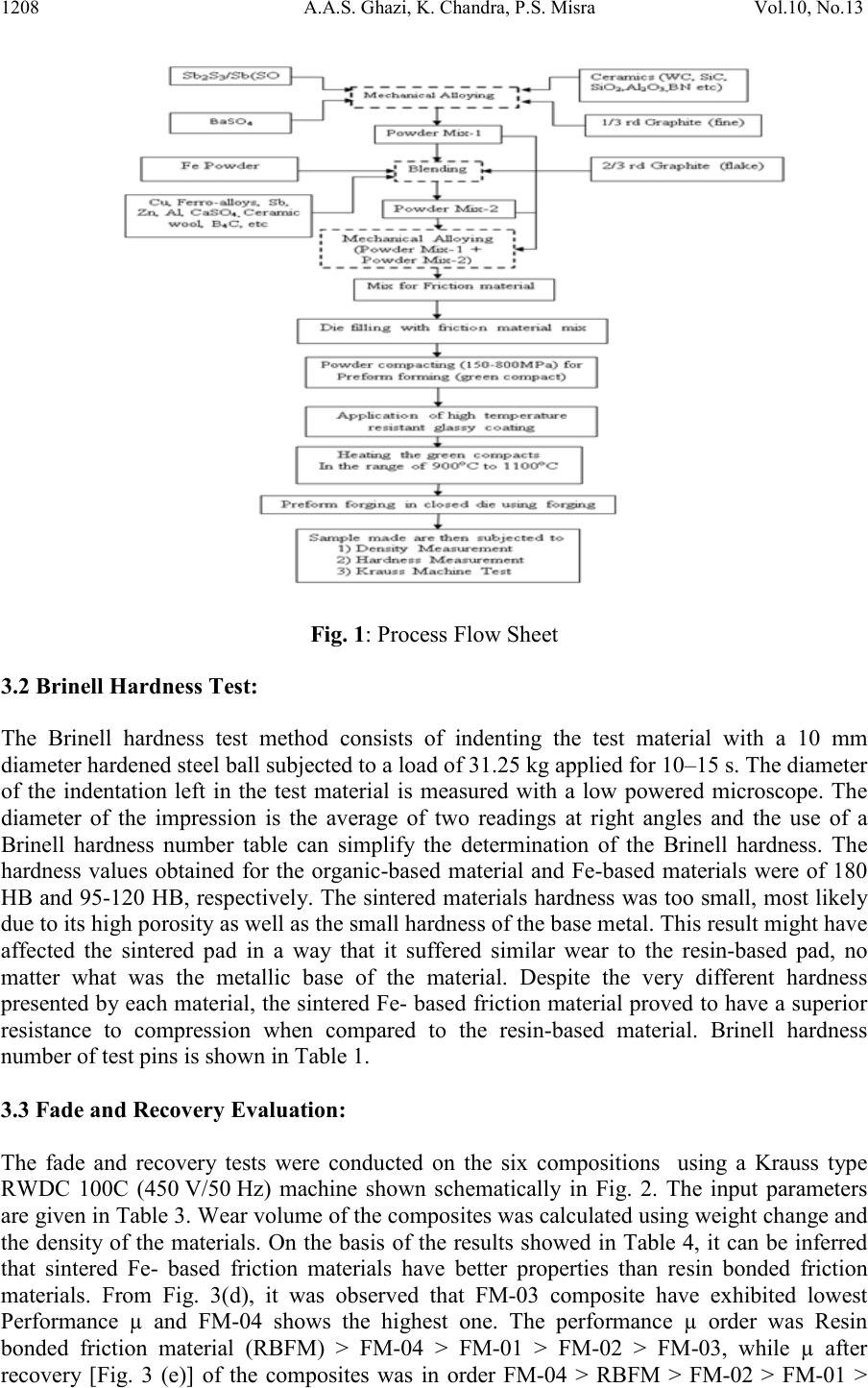
compacts are th en coated with high tem perature resis tant cer amic glassy coating [10] and are
dried completely. The purpose of this coating is to protect samples from oxidation at high
Vol.10, No.13 Development and Characterization 1207
temperature. The green compacts so produced are heated in a furnace. The operating
temperature of the furnace ranges from 1050OC 1100OC for iron based brake pad and the
holding time is 1/2 hours.
Table 1: Chemistry of friction materials, density and hardness
Table 2: Particle size of powders employed
The hot powder preforms are then taken out from the furnace and quickl y transferred into the
hot lubricated die fitted in the forging press (capacity of press depending upon area of the
actual brake pad) and having speed 50-500 mm/s. The preform is fully consolidates to its
near theoretical density on forging. The for ged component is thereafter ejected out of the die.
Forged samples are again coated with glassy coating, and then they are annealed at a
temperature of 710oC for 2 hours durations. The process flow sheet is given in Fig. 1.
3. RESULTS AND DISCUSSION
3.1 Determination of Density:
The basic method of determining the density of Krauss Machine Tester sample is by
measuring the ratio of mass and volume of the specimen was used. Density depends upon
extent of forging and normalizing/annealing treatments thereafter. It also indirectly depends
upon chemistry of friction materials. In this paper, the densities of Krauss Machine Tester
sampl es are estimat ed by Archi medes prin ciple as shown in Tabl e 1. The d ensity of S intered
Fe-based samples are higher than resin bonded friction material which results in better
properties of sintered material.
1208 A.A.S. Ghazi, K. Chandra, P.S. Misra Vol.10, No.13
Fig. 1: Process Flow Sheet
3.2 Brinell Hardness Test:
The Brinell hardness test method consists of indenting the test material with a 10 mm
diameter hardened steel ball subjected to a load of 31.25 kg applied for 10–15 s. The diameter
of the indentation left in the test material is measured with a low powered microscope. The
diameter of the impression is the average of two readings at right angles and the use of a
Brinell hardness number table can simplify the determination of the Brinell hardness. The
hardness values obtained for the organic-based material and Fe-based materials were of 180
HB and 95-120 HB, respectively. The sintered materials hardness was too small, most likely
due to its high porosity as well as the small hardness of the base metal. This result might have
affected the sintered pad in a way that it suffered similar wear to the resin-based pad, no
matter what was the metallic base of the material. Despite the very different hardness
presented by each mate rial, the si ntered Fe- based friction material proved to have a superior
resistance to compression when compared to the resin-based material. Brinell hardness
number of test pins is shown in Table 1.
3.3 Fade and Recovery Evaluation:
The fade and recovery tests were conducted on the six compositions using a Krauss type
RWDC 100C (450 V/50 Hz) machine shown schematically in Fig. 2. The input parameters
are given i n T abl e 3. W e ar vol um e of t he co mp osites was cal cul ated us ing weight ch an ge and
the density of the materials. On the basis of the results showed in Table 4, it can be inferred
that sintered Fe- based friction materials have better properties than resin bonded friction
materials. From Fig. 3(d), it was observed that FM-03 composite have exhibited lowest
Performance µ and FM-04 shows the highest one. The performance µ order was Resin
bonded friction material (RBFM) > FM-04 > FM-01 > FM-02 > FM-03, while µ after
recovery [Fig. 3 (e)] of the composites was in order FM-04 > RBFM > FM-02 > FM-01 >
Vol.10, No.13 Development and Characterization 1209
FM-03. The fade µ [Fig. 3(c)] order is RBFM > FM-01 > FM-04 > FM-02 > FM-03 and it
shows that fade µ is lowest for FM-03. The % age fade [Fig. 3 (a)] is lowest for FM-01 and
follows the order FM-04 > FM-02 > RBFM > FM-03 > FM-01. The % age recovery [Fig.
3(b)] is maximum for FM-02 and follows the order FM-02 > FM-04 > FM-01 > FM-03 >
RBFM. The temperature order is as follows RBFM > FM-04 > FM-02 > FM-01 > FM-03
[Fig. 3(f)]. The fad e and recovery chara cterist ics of all the fou r com posi tes st udied have be en
observed to be well within the IS 2742 prescribed permissible ranges of 0–30 and 90–140 %,
respectively. Therefore, sintered Fe- based friction materials are superior to resin bonded
friction materials.
Fig. 2 : Schematic of Krauss Machine: (1) compressed air supply, (2) bearings movable, (3) bearings,
(4) option SH 2.5 kg m m, (5) emergency stop option, (6) bearings,(7) options SH 5 kg m 2, (8) air
inlet, (9) d. c. motor, (10) clutch at option SH, (11) belt drive and (12) generator.
Table 3: Input param eters for Krau ss Test Table 4: Results for Fe-based and Resin
Bonded Frict ion Mater ia ls (Kraus s Machin e Tes t)
Fig. 3(a): % age Fade Vs Friction Materials Fig. 3(b): % age Recovery Vs Friction Materials
1210 A.A.S. Ghazi, K. Chandra, P.S. Misra Vol.10, No.13
Fig. 3(c): µfa de Vs Friction Materials Fig. 3(d): µperformance Vs Friction Materials
Fig. 3(e): µrecovery Vs Friction Materials Fig. 3(f): Temperature Rise Vs Friction
Material s
3.4 SEM/EDAX:
In order to get the detail ed information about different constituents, EDAX anal ysis was als o
performed including their micro-analysis. Fig. 4 (a), (b) & (c) shows the SEM/EDAX of the
friction material FM-01, FM-02 and FM-03 resp..
Fig. 4(a): SEM/EDX of FM-01
Vol.10, No.13 Development and Characterization 1211
Fig. 4(b): SEM/EDX of FM-02
Fig. 4(c): SEM/EDX of FM-03
4. CONCLUSIO NS
Based on the results obtained, the sintered Fe- based friction materials proved to be more
efficient than the resin-based friction materials because it presents a relatively lower wear
rate as well as a higher friction coefficient. The wear rate in the sintered material was lower
due to the good ductility of its metallic matrix. Due to the presence of SiC, it was possible to
obtain an increase of the friction coefficient in the sintered material. To improve the thermal
conductivity of the material, it is important to decrease the matrix porosity, so that it is
possible to improve the brake pad efficiency. As previously mentioned, studies about friction
materials are based on trial and error testing procedures. It is through changes in the base
materials, in the manufacturing processes and even in the work conditions that really different
result s can be noti ced. The p resent st udy suggest s that ea ch friction material n eeds a speci fic
focus of study. Iron based brake pads can be used for low duty applications. The technology
completely eliminates the problems of joining between backing plate and friction element on
account of simultaneous application of pressure and temperature. Th e p oro s i t y of the m aterial
may cause higher temperature increase when the system operates because the pores work as
insulators in the material, and they make the heat transference difficult. In one instance, this
increasing in porosity presented some benefits related to the application of the friction
material, since it increases the material roughness, promoting an increase in the friction with
the brake disc. Another benefit brought about by porosity was to keep the abrasive particles
in the material, avoiding their loss during braking action.
1212 A.A.S. Ghazi, K. Chandra, P.S. Misra Vol.10, No.13
REFERENCES
1. M. Eriksson, “Friction and contact phenomena of disc brakes related to squeal”,
Comprehensive summaries of Uppsala dissertations from the Faculty of Science and
Technology 537, ACTA Universitatis Upsaliensis, 2000.
2. S. J. Kim, M. H. Cho, D. S. Lim, H. Jang, Wear 251, 2001, pp. 1484–1491.
3. S. J. Kim, H. Jang, Tribol. Int. 33, 2000, pp. 477–484.
4. A. P. Verma, B. Vishwanath, C. V. S. Kameswara Rao, Wear 193, 1996, pp.193–198.
5. H. Jan g, S. J. Kim, Wear 239, 2000, pp. 229–236.
6. T. Kato, A. Magario, Tribol. Trans. 37, 1994, pp. 559–565.
7. Luise Gudmand-Høyer , Allan Bach , Georg T. Nielsen , Per Morgen, Wear 232, 1999,
pp. 168– 75.
8. R. H. T. Dixon, C layton A., “Powder Metallurgy for engineers, Machinery Publishing
Co. Ltd., London, 1971, pp. 166-183.
9. D. Dutta, G. Mohan, B. Chatterjee, C. G. Krishnadas Nair, “Development of sintered
metalloceramic friction material for the wheel brakes of a military transport aircraft”,
published in, ‘Composites: Science and Technology (ISBN 81-224-1251-3), edited by
R.C. Prasad, P. Ramakrishan, New Age International (P) Ltd., New Delhi, 2002, pp. 94-
114.
10. P. S. Misra, K. Chandra, “Development of High Temperature Oxidation Resistant Glassy
Coating”, Indian Patent, Application no. 153/DEL/2010 dated Jan. 27, 2010.