Paper Menu >>
Journal Menu >>
 Journal of Minerals & Materials Characterization & Engineering, Vol. 10, No.11, pp.1087-1102, 2011 jmmce.org Printed in the USA. All rights reserved 1087 Parametric Optimization of PMEDM Process using Chromium Powder Mixed Dielectric and Triangular Shape Electrodes Kuldeep Ojha 1*, R. K. Garg 1 , K. K. Singh 2 1 Department of Industrial and Production Engineering, Dr B. R. Ambedkar National Institute of Technology, Jalandhar-144011, Punjab, India 2 Department of Mechanical Engineering & Mining Machinery Engineering, Indian School of Mines (ISM), Dhanbad-826004, Jharkhand, India *Corresponding Author: kojha.gvc@gmail.com ABATRACT In this article, parametric optimization for material removal rate (MRR) and tool wear rate (TWR) study on the powder mixed electrical discharge machining (PMEDM) of EN-8 steel has been carried out. Response surface methodology (RSM) has been used to plan and analyze the experiments. Average current, duty cycle, angle of electrode and concentration of chromium powder added into dielectric fluid of EDM were chosen as process parameters to study the PMEDM performance in terms of MRR and TWR. Experiments have been performed on newly designed experimental setup developed in laboratory. Most important parameters affecting selected performance measures have been identified and effects of their variations have been observed. Keywords: EDM; PMEDM; MRR; TWR; Optimization 1. INTRODUCTION Electrical discharges machining (EDM) is an important manufacturing process for tool mould and die industries. This process is finding increasing application because of its ability to produce geometrically complex shapes and its ability to machine materials irrespective to their hardness. However, poor surface finish and low machining efficiency in comparison to other non conventional machining process limits its further applications [1, 2]. Powder mixed electrical  1088 Kuldeep Ojha , R. K. Garg, K. K. Singh Vol.10, No.11 discharge machining (PMEDM) is a relatively new material removal process applied to improve the machining efficiency and surface finish in presence of powder mixed dielectric fluid [1, 3- 13]. Researchers explained the working principle of powder mixed electrical discharge machining process [1, 14]. When a voltage is applied between the electrode and the work piece facing each other with a gap, an electric field in the range of 10 5 –10 7 V/m is created. The powder particles in the spark gap get energized. These charged particles are accelerated by the developed electric field and act as conductors. The conductive particles promote breakdown in the gap and also increase the spark gap between tool and the workpiece. Under the sparking area, the particles come closer and arrange themselves in chain like structures between both the electrodes. The interlocking between the different powder particles takes place in the direction of current flow. This chain formation helps in bridging the discharge gap between electrodes and also results in decreasing the insulating strength of the dielectric fluid. The easy short circuit takes place, causing early explosion in the gap resulting in series discharges under the electrode area. The faster sparking within a discharge occur causing faster erosion from the workpiece surface and hence the material removal rate (MRR) increases. At the same time, the added powder also modifies the plasma channel making it enlarged and widened. The sparks are uniformly distributed among the powder particles, hence electric density of the spark decreases. Due to uniform distribution of sparks among the powder particles, shallow craters are produced on the workpiece surface resulting in improvement in surface finish. 2. LITERATURE REVIEW Erden et al. [10] investigated the effect of abrasive powder mixed into the dielectric fluid and proposed that the machining rate increased with an increase of the powder concentration due to decreasing the time lag. Jeswani [11] investigated the effect of addition of graphite powder to kerosene and proposed that the material removal rate was improved around 60% and electrode wear ratio was reduced about 15% by using the kerosene oil mixed with 4 g/l graphite powder. Mohri et al. [12, 15, 16], Yan et al. [17-19], and Uno et al. [20] investigated the influence of silicon powder addition on machining rate and surface roughness in EDM. Furutani et al. [7], Wong et al. [21, and Yan et al. [22] proposed that the machined surface properties, including hardness, wear resistance, and corrosion resistance could be significantly improved by using the PMEDM process. Wu [23] discussed the improvement of the machined surface by adding aluminum powder and surfactant into dielectric fluid. Surfactants are compounds that lower the surface tension of a liquid, the interfacial tension between two liquids, or that between a liquid and a solid. Surfactants may act as detergents, wetting agents, emulsifiers, foaming agents, and dispersants. Polyoxythylene-20-sorbitan monooleate was added as surfactant in his work. Narumiya et al. [5] concluded that Al and Si powders yield better surface finish under specific working conditions. Kobayashi et al. [24] investigated the effects of suspended powder in  Vol.10, No.11 Parametric Optimization of PMEDM Process 1089 dielectric fluid on MRR and SR of SKD-61 material. Uno et al. [25] Studied the effect of nickel powder mixed with working fluid modifies the surface of aluminum bronze components. Okada et al. [26] proposed a new method for forming hard layer containing titanium carbide by EDM with carbon powder mixed fluid using titanium electrode. Chow et al. [27] studied the EDM process by adding SiC and aluminum powders into kerosene for the micro-slit machining of titanium alloy. Wang et al. [28] investigated the effect of Al and Cr powder mixture in kerosene. Tzeng and Lee [3] reported the effect of various powder characteristics on EDM of SKD-11 material. Furutani and Shiraki [29] proposed a deposition method of lubricant layer during finishing EDM process to produce parts for ultra high vacuum. Simao [30] explored the role of PMEDM in modifying the surface properties of the workpiece by application of Taguchi method. Pecas and Henriques [31] Investigated the influence of silicon powder mixed dielectric on conventional EDM. The relationship between the roughness and pulse energy was roughly investigated under a few sets of the conditions in the removal process. However, the effect of the energy was not systematically analyzed. Kansal [14] worked to optimize the process parameters of PMEDM by using the response surface methodology. Çogun et al. [32] made an experimental investigation on the effect of powder mixed dielectric on machining performance. Kansal et al. [33] studied the effect of Silicon powder mixed EDM on machining Rate of AISI D2 Die Steel. P. Pecas et al. [34, 35] investigated the effect of the electrode area in the surface roughness and topography and also the influence of the powder concentration and dielectric flow in the surface morphology. Prihandana et al. [36] investigated the effect of micro-powder suspension and ultrasonic vibration of dielectric fluid in micro-EDM processes by applying the Taguchi approach. Furutani et al. [37] investigated the influence of electrical conditions on performance of electrical discharge machining with powder suspended in working oil for titanium carbide deposition process. Kung et al. [38] studied the influence of MRR and electrode wear ratio in the PMEDM of cobalt-bonded tungsten carbide. Kojha et al. [39, 40] investigated the effect of Nickel Micro Powder Suspended Dielectric on EDM Performance Measures of EN-19 Steel. Elaborate scrutiny of the literature reveals that material removal mechanism of PMEDM process is very complex and theoretical modeling of the process is very difficult. Regarding empirical results, much research work is required with more work-tool-powder-parametric combinations to make the process commercially applicable. Also, most of the research work is with Al, Si, and graphite powders. Much investigation is needed regarding other types of powder like Cr, Ni, Mo, etc. Also, EDM performance measures are influenced by electrode design [41- 43]. There is a literature gap regarding investigation of influence of electrode profile parameters on PMEDM performance measures. In present research work, different parametric combinations of average current, duty cycle, angle of triangular electrode, and powder concentration of chromium in dielectric have been explored for EN- 8 steel. Literature review reveals that this combination has not been explored yet. EN-8 steel finds wide applications in fabrication of components of small cross section, requiring low 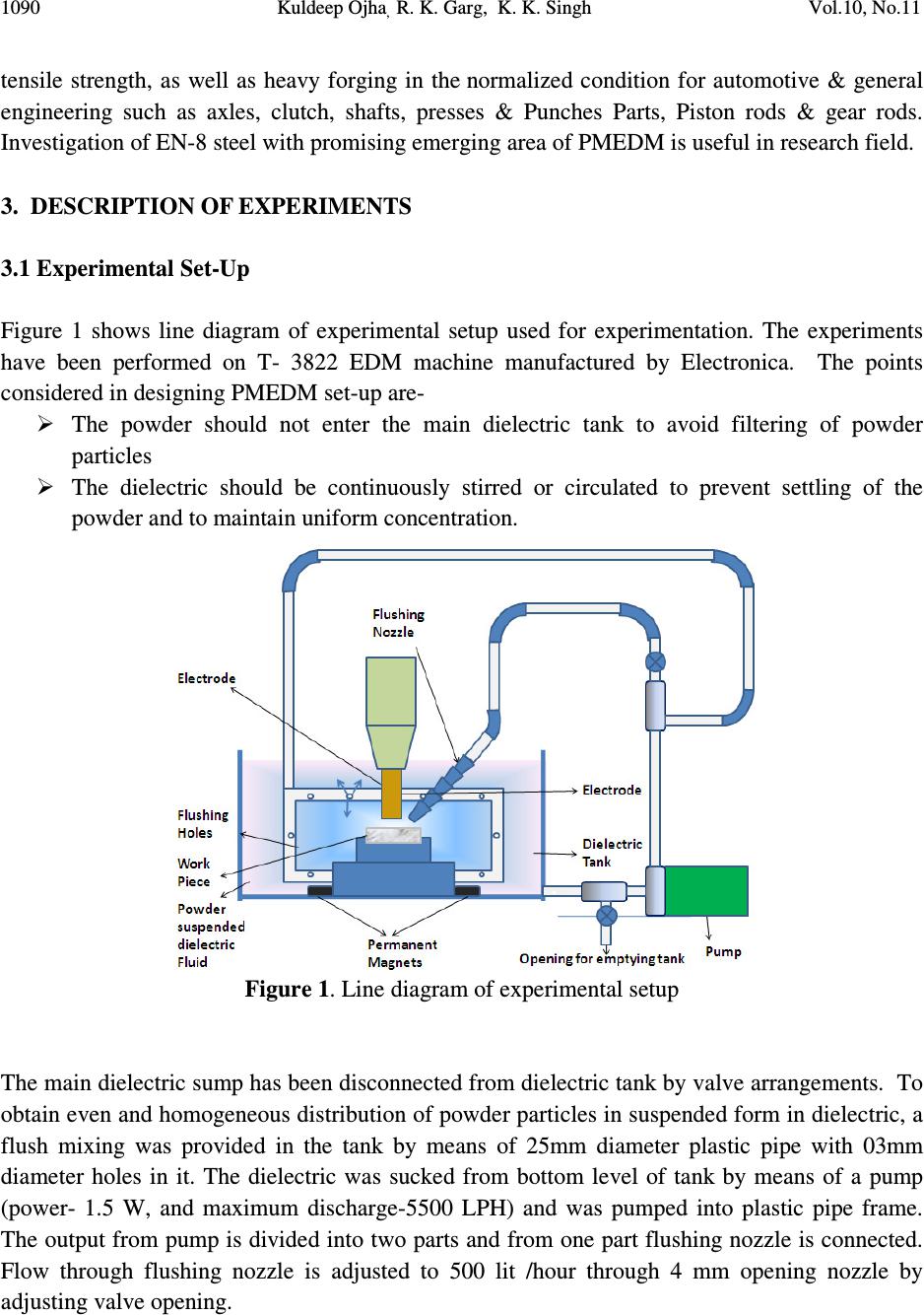 1090 Kuldeep Ojha , R. K. Garg, K. K. Singh Vol.10, No.11 tensile strength, as well as heavy forging in the normalized condition for automotive & general engineering such as axles, clutch, shafts, presses & Punches Parts, Piston rods & gear rods. Investigation of EN-8 steel with promising emerging area of PMEDM is useful in research field. 3. DESCRIPTION OF EXPERIMENTS 3.1 Experimental Set-Up Figure 1 shows line diagram of experimental setup used for experimentation. The experiments have been performed on T- 3822 EDM machine manufactured by Electronica. The points considered in designing PMEDM set-up are- The powder should not enter the main dielectric tank to avoid filtering of powder particles The dielectric should be continuously stirred or circulated to prevent settling of the powder and to maintain uniform concentration. Figure 1. Line diagram of experimental setup The main dielectric sump has been disconnected from dielectric tank by valve arrangements. To obtain even and homogeneous distribution of powder particles in suspended form in dielectric, a flush mixing was provided in the tank by means of 25mm diameter plastic pipe with 03mm diameter holes in it. The dielectric was sucked from bottom level of tank by means of a pump (power- 1.5 W, and maximum discharge-5500 LPH) and was pumped into plastic pipe frame. The output from pump is divided into two parts and from one part flushing nozzle is connected. Flow through flushing nozzle is adjusted to 500 lit /hour through 4 mm opening nozzle by adjusting valve opening. 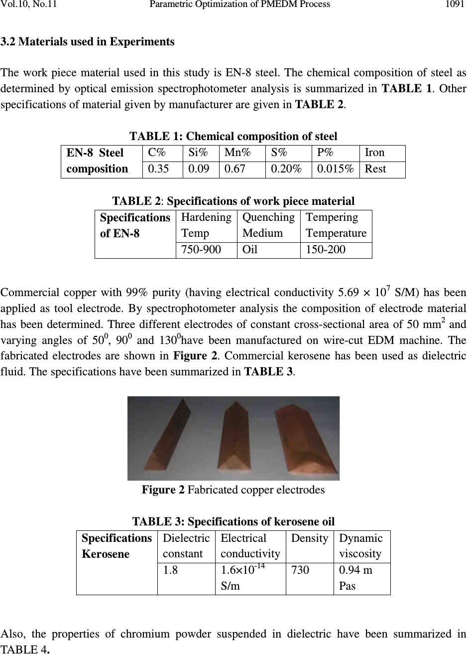 Vol.10, No.11 Parametric Optimization of PMEDM Process 1091 3.2 Materials used in Experiments The work piece material used in this study is EN-8 steel. The chemical composition of steel as determined by optical emission spectrophotometer analysis is summarized in TABLE 1. Other specifications of material given by manufacturer are given in TABLE 2. TABLE 1: Chemical composition of steel EN-8 Steel composition C% Si% Mn% S% P% Iron 0.35 0.09 0.67 0.20% 0.015% Rest TABLE 2: Specifications of work piece material Specifications of EN-8 Hardening Temp Quenching Medium Tempering Temperature 750-900 Oil 150-200 Commercial copper with 99% purity (having electrical conductivity 5.69 × 10 7 S/M) has been applied as tool electrode. By spectrophotometer analysis the composition of electrode material has been determined. Three different electrodes of constant cross-sectional area of 50 mm 2 and varying angles of 50 0 , 90 0 and 130 0 have been manufactured on wire-cut EDM machine. The fabricated electrodes are shown in Figure 2. Commercial kerosene has been used as dielectric fluid. The specifications have been summarized in TABLE 3. Figure 2 Fabricated copper electrodes TABLE 3: Specifications of kerosene oil Specifications Kerosene Dielectric constant Electrical conductivity Density Dynamic viscosity 1.8 1.6×10 - 14 S/m 730 0.94 m Pas Also, the properties of chromium powder suspended in dielectric have been summarized in TABLE 4. 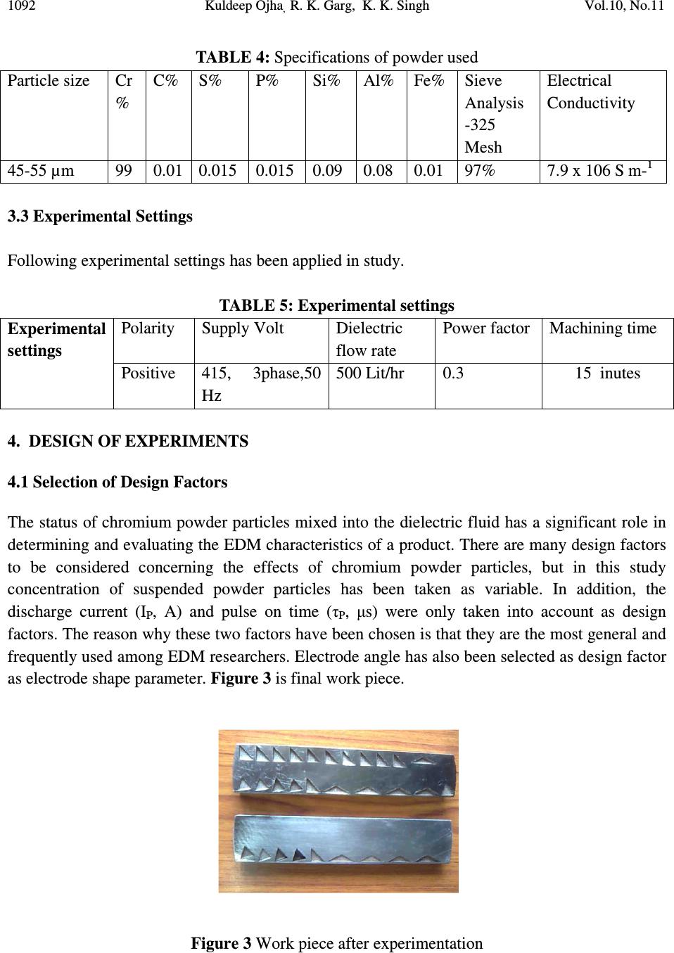 1092 Kuldeep Ojha , R. K. Garg, K. K. Singh Vol.10, No.11 TABLE 4: Specifications of powder used Particle size Cr % C% S% P% Si% Al% Fe% Sieve Analysis -325 Mesh Electrical Conductivity 45-55 µm 99 0.01 0.015 0.015 0.09 0.08 0.01 97% 7.9 x 10⁶ S m - 1 3.3 Experimental Settings Following experimental settings has been applied in study. TABLE 5: Experimental settings Experimental settings Polarity Supply Volt Dielectric flow rate Power factor Machining time Positive 415, 3phase,50 Hz 500 Lit/hr 0.3 15 inutes 4. DESIGN OF EXPERIMENTS 4.1 Selection of Design Factors The status of chromium powder particles mixed into the dielectric fluid has a significant role in determining and evaluating the EDM characteristics of a product. There are many design factors to be considered concerning the effects of chromium powder particles, but in this study concentration of suspended powder particles has been taken as variable. In addition, the discharge current (I P , A) and pulse on time (τ P , µs) were only taken into account as design factors. The reason why these two factors have been chosen is that they are the most general and frequently used among EDM researchers. Electrode angle has also been selected as design factor as electrode shape parameter. Figure 3 is final work piece. Figure 3 Work piece after experimentation  Vol.10, No.11 Parametric Optimization of PMEDM Process 1093 4.2 Selection of Response Variables The response variables selected in this study were MRR and TWR. Both MRR and TWR refer to the machining efficiency of the PMEDM process and the wear of copper electrode, respectively, and are defined as follows. MRR (mm 3 /min) = (Wear weight of work piece)/ (time of machining× density of work piece material) TWR (mm 3 /min) = (Wear weight of tool electrode)/ (time of machining× density of electrode material) The work piece and electrode were weighed before and after each experiment using an electric balance with a resolution of 0.001 mg to determine the value of MRR and TWR. For efficient evaluation of the PMEDM process, the larger MRR and the smaller TWR are regarded as the best machining performance. Therefore, the MRR is considered as a “the larger-the-better characteristic” and the TWR is considered as “the smaller-the-better characteristic” in this experimentation. 4.3 Experimental Design Response surface methodology (RSM) is used in design matrix formation which is an empirical modeling approach using polynomials as the local approximations to obtain true input/output relationships. The experimental plans were designed on the basis of the central composite design (CCD) technique of RSM. The factorial portion of CCD is a full factorial design with all combinations of the factors at two levels (high, +1 and low, −1) and composed of the eight star points and seven central points (coded level 0). Central points are the midpoint between the high and low levels. The star points are at the face of the cube portion on the design that corresponds to an α value of 1, and this type of design is commonly called the “face-centered CCD”. In this study, the experimental plan was conducted using the stipulated conditions according to the face- centered CCD and involved a total of 30 experimental observations at four independent input variables. The machining time for each experimental specimen is 15 min. This was set up before the operation of the machine reached the stable state. The levels of design factors have been selected in accordance with literature consulted as well as by personal experience. The design factors selected for study with their low and high levels are summarized in TABLE 6. Design Expert 8.0.4 software was used for design of experiments, and regression and graphical analysis of data obtained. The optimum conditions have been obtained by solving the regression equations and by analyzing response surface contours.  1094 Kuldeep Ojha , R. K. Garg, K. K. Singh Vol.10, No.11 TABLE 6: Process parameters and their levels Parameters Notation Unit Range and levels Natural Coded -1 0 +1 Current I X 1 A 4 6 8 Duty cycle (%) D (%) X 2 % 54 63 72 Powder concentration C X 3 g/l 2 4 6 Tool angle A X 4 Degree 50 90 130 5. RESPONSE SURFACE MODELING As stated earlier Response surface methodology has been applied for modeling and analysis of parameters. The quantitative relationship between desired responses and independent process variables can be represented as Y= f (X 1 , X 2 , X 3, ……………. X n ) Where Y is the desired response, f is the response function and X1, X2... are independent parameters. By plotting the expected responses, a surface known as Response surface is obtained. RSM aims at approximating f by using the fitted second order polynomial regression model which is called the quadratic model. The model can be represented as follows- n n Y=C 0 + ∑ C i X n +∑ d i X i2 ± € I=1 i=1 6. RESULTS AND DISCUSSIONS 30 experimental runs have been conducted and values of MRR and TWR along with design matrix are given in TABLE 7 to avoid any systematic error creeping into system. Analysis of variance (ANOVA) is performed on collected data for testing significance of regression model and model coefficients.  Vol.10, No.11 Parametric Optimization of PMEDM Process 1095 TABLE 7: Experimental design matrix and collected data Run No Coded values Natural Values Responses X 1 X 2 X 3 X 4 I (A) D (%) C (g/l) D (Deg ree) MRR (mm 3 /min) TWR (mm 3 /min) 1 0 0 0 0 6 63 4 90 8.61 0.04 2 +1 0 0 0 8 63 4 90 7.78 0.035 3 0 0 0 +1 6 63 4 130 5.83 0.033 4 -1 -1 -1 -1 4 54 2 50 1.72 0.03 5 0 0 0 0 6 63 4 90 8.64 0.031 6 0 0 -1 0 6 63 2 90 8.01 0.022 7 -1 0 0 0 4 63 4 90 7.98 0.029 8 +1 +1 -1 +1 8 72 2 130 6.66 0.021 9 +1 +1 -1 -1 8 72 2 50 5.42 0.036 10 0 0 0 0 6 63 4 90 7.89 0.028 11 +1 +1 +1 +1 8 72 6 130 13.41 0.034 12 +1 -1 -1 +1 8 54 2 130 3.25 0.039 13 -1 -1 +1 +1 4 54 6 130 3.31 0.016 14 -1 -1 -1 +1 4 54 2 130 2.74 0.013 15 +1 -1 -1 -1 8 54 2 50 8.72 0.041 16 +1 +1 +1 -1 8 72 6 50 9.02 0.033 17 0 0 0 0 6 63 4 90 7.76 0.031 18 +1 -1 +1 -1 8 54 6 50 11.01 0.035 19 +1 -1 +1 +1 8 54 6 130 10.31 0.032 20 0 -1 -1 0 6 54 4 90 7.79 0.034 21 0 +1 -1 0 6 72 4 90 6.52 0.026 22 -1 +1 -1 -1 4 72 2 50 1.54 0.016 23 -1 +1 +1 +1 4 72 6 130 2.09 0.02 24 0 0 +1 +1 6 63 6 90 6.65 0.032 25 -1 +1 +1 -1 4 72 6 50 3.28 0.033 26 0 0 0 0 6 63 4 90 7.53 0.026 27 -1 -1 +1 -1 4 54 6 50 2.75 0.025 28 0 0 0 0 6 63 4 90 7.98 0.031 29 0 0 0 -1 6 63 4 50 5.87 0.035 30 -1 +1 -1 +1 4 72 2 130 1.59 0.019  1096 Kuldeep Ojha , R. K. Garg, K. K. Singh Vol.10, No.11 6.1 Analysis of MRR Figure 4, Figure 5 and Figure 6 shows the estimated response surface for MRR in relation to the design parameters of average current with tool angle, powder concentration and duty cycle. As can be seen from these figures, the MRR tends to increase, considerably with increase in current for any value of other factors. Hence, maximum MRR is obtained at high current. The MRR increases with increase in tool angle owing to increase in current. After certain level, the MRR tends to decrease due to inefficient flushing. MRR is found to increase with duty cycle and powder concentration. Powder concentration has much significant effect on MRR. Figure 4 Response surface for MRR showing effect of current and tool angle and powder concentration Figure 5 Response surface for MRR showing effect of current and powder concentration  Vol.10, No.11 Parametric Optimization of PMEDM Process 1097 Figure 6 Response surface for MRR showing effect of current and duty cycle 6.2 Analysis of TWR Figure 7, Figure 8 and Figure 9 shows the estimated response surface for TWR in relation to the design parameters of average current with tool angle, powder concentration and duty cycle. As can be seen from these figures, only current and electrode angle are dominant parameter affecting TWR. The TWR decreases with increase in tool angle. Figure 7 Response surface for TWR showing effect of current and powder concentration Figure 8 Response surface for TWR showing effect of current and duty cycle  1098 Kuldeep Ojha , R. K. Garg, K. K. Singh Vol.10, No.11 Figure 9 Response surface for TWR showing effect of current and tool angle 6.3 Parametric Optimization Optimization of parameters with the help of software suggests the following results. Following constraints on the design space has been applied as shown in TABLE 8. TABLE 8: Constraints in design space Constraints Name Goal Limit Limit Weight Weight Importance A In range 4 8 1 1 3 B In range 54 72 1 1 3 C In range 2 6 1 1 3 D In range 50 130 1 1 3 MRR Maximize 1.54 13.41 1 1 3 TWR Minimize 0.013 0.041 1 1 3 Following solution has been suggested by software for optimum parameter settings. 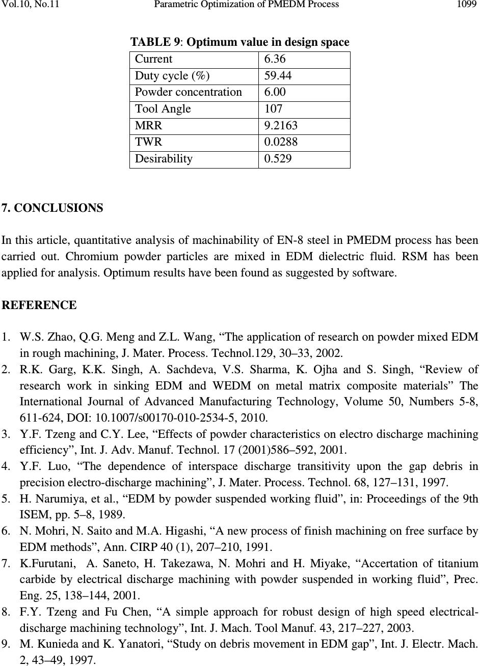 Vol.10, No.11 Parametric Optimization of PMEDM Process 1099 TABLE 9: Optimum value in design space Current 6.36 Duty cycle (%) 59.44 Powder concentration 6.00 Tool Angle 107 MRR 9.2163 TWR 0.0288 Desirability 0.529 7. CONCLUSIONS In this article, quantitative analysis of machinability of EN-8 steel in PMEDM process has been carried out. Chromium powder particles are mixed in EDM dielectric fluid. RSM has been applied for analysis. Optimum results have been found as suggested by software. REFERENCE 1. W.S. Zhao, Q.G. Meng and Z.L. Wang, “The application of research on powder mixed EDM in rough machining, J. Mater. Process. Technol.129, 30–33, 2002. 2. R.K. Garg, K.K. Singh, A. Sachdeva, V.S. Sharma, K. Ojha and S. Singh, “Review of research work in sinking EDM and WEDM on metal matrix composite materials” The International Journal of Advanced Manufacturing Technology, Volume 50, Numbers 5-8, 611-624, DOI: 10.1007/s00170-010-2534-5, 2010. 3. Y.F. Tzeng and C.Y. Lee, “Effects of powder characteristics on electro discharge machining efficiency”, Int. J. Adv. Manuf. Technol. 17 (2001)586–592, 2001. 4. Y.F. Luo, “The dependence of interspace discharge transitivity upon the gap debris in precision electro-discharge machining”, J. Mater. Process. Technol. 68, 127–131, 1997. 5. H. Narumiya, et al., “EDM by powder suspended working fluid”, in: Proceedings of the 9th ISEM, pp. 5–8, 1989. 6. N. Mohri, N. Saito and M.A. Higashi, “A new process of finish machining on free surface by EDM methods”, Ann. CIRP 40 (1), 207–210, 1991. 7. K.Furutani, A. Saneto, H. Takezawa, N. Mohri and H. Miyake, “Accertation of titanium carbide by electrical discharge machining with powder suspended in working fluid”, Prec. Eng. 25, 138–144, 2001. 8. F.Y. Tzeng and Fu Chen, “A simple approach for robust design of high speed electrical- discharge machining technology”, Int. J. Mach. Tool Manuf. 43, 217–227, 2003. 9. M. Kunieda and K. Yanatori, “Study on debris movement in EDM gap”, Int. J. Electr. Mach. 2, 43–49, 1997.  1100 Kuldeep Ojha , R. K. Garg, K. K. Singh Vol.10, No.11 10. A. Erden and S. Bilgin, “Role of impurities in electric discharge machining”, in: Proceedings of the 21st International Machine Tool Design and Research Conference, Macmillan, London, pp. 345– 350, 1980. 11. M.L. Jeswani, “Effects of the addition of graphite powder to kerosene used as the dielectric fluid in electrical discharge machining”, Wear 70, 133–139, 1981. 12. N. Mohri, et al., “Mirror-like finishing by EDM”, in: Proceedings of the 25th International Symposium on Machine Tool Design and Research, UK, pp. 329–336, 1985. 13. H. Kansal, S. Singh and P. Kumar, “State of the art concerning powder mixed EDM”, in: Proceedings of the International Conference on Emerging Technology (ICET-2003) KIIT, Bhubansewar, India, 2003. 14. H. K. Kansal, S. Singh and P. Kumar, “Parametric optimization of powder mixed electrical discharge machining by response surface methodology”, Journal of Materials Processing Technology 169, 427–436, 2005. 15. N. Mohri, J. Tsukamoto and M. Fujino, “Surface modification by EDM—an innovation in EDM with semi-conductive electrodes”, in: Proceedings of Winter Annual Meet ASME, vol. 34, pp. 21–30, 1988. 16. N. Mohri, N. Saito and M.A. Higashi, “A new process of finish machining on free surface by EDM methods”, Ann. CIRP 40 (1), 207–210, 1981. 17. B.H. Yan and S.L. Chen, “Effects of dielectric with suspended aluminum powder on EDM”, J. Chin. Soc. Mech. Eng. 14 (3), 307–312, 1993. 18. B.H. Yan and S.L. Chen, “Characteristics of SKD11 by complex process of electric discharge machining using liquid suspended with aluminum powder”, J. Jpn. Inst. Light Met. 58 (9), 1067–1072, 1994. 19. B.H. Yan and S.L. Chen, “Effect of ultrasonic vibration on electrical discharge machining characteristics of Ti–6Al–4V alloy”, J. Jpn. Inst. Light Met. 44 (5), 281–285, 1994. 20. Y. Uno and A. Okada, “Surface generation mechanism in electrical discharge machining with silicon powder mixed fluid”, Int. J. Elec. Mach. 2, 13–18, 1997. 21. Y.S. Wong, L.C. Lim, I. Rahuman and W.M. Tee, “Near-mirror-finish phenomenon in EDM using powder-mixed dielectric”, Int. J. Adv. Manuf. Technol. 79, 30–40, 1998. 22. B.H. Yan, Y.C. Lin, F.Y. Huang and C.H. Wang, “Surface modification of SKD 61 during EDM with metal powder in the dielectric”, Mater Trans 42(12):2597–2604, 2004. 23. K.L. Wu, B.H. Yan, F.Y. Huang and S.C. Chen, “Improvement of surface finish on SKD steel using electro-discharge machining with aluminum and surfactant added dielectric”, Int J Mach Tools Manu 45:1195–1201, 2005. 24. K. Kobayashi, T. Magara, Y. Ozaki and T. Yatomi, “The present and future developments of electrical discharge machining”, in: Proceedings of 2nd International Conference on Die and Mould Technology, Singapore, pp. 35–47, 1992. 25. Y. Uno, A. Okada, Y. Hayashi and Y. Tabuchi, “Surface integrity in EDM of aluminum bronze wit nickel powder mixed fluid”, J. Jpn. Soc. Elec. Mach. Eng. 32 (70), 24–31 (in Japanese), 1998.  Vol.10, No.11 Parametric Optimization of PMEDM Process 1101 26. A. Okada, Y. Uno and K. Hirao, “Formation of hard layer by EDM with carbon powder mixed fluid using titanium electrode”, in: Proceedings of 5th International Conference on Progress of Machining Technology, pp. 464–469, 2000. 27. H.M. Chow, B.H. Yan, F.Y. Huang and J.C. Hung, “Study of added powder in kerosene for the micro-slit machining of titanium alloy using electro-discharge machining”, J. Mater. Process. Technol. 101, 95–103, 2000. 28. Wang, C.H., Lin, Y.C., Yan, B.H., Huang, F.Y. (2001), “Effect of characteristics of added powder on electrical discharge machining”, J. Jpn. Inst. Light Met., 42(12), 2597-2604. 29. K. Furutani and K. Shiraki, “Deposition of lubricant layer during finishing process by electrical discharge machining with molybdenum disulphide powder suspended in working fluid”, in: JSME/ASME International Conference on Materials and Processing, 2002, pp. 468–473, 2002. 30. J. Simao, “Work piece surface modification using electrical discharge machining”, Int. J. Mach. Tools Manuf. 43, 121–128, 2003. 31. P. Pecas and E.A. Henriques, “Influence of silicon powder mixed dielectric on conventional electrical discharge machining”, Int. J. Mach. Tools Manuf. 43, 1465–1471, 2003. 32. C. Cogun, B. Ozerkan and T.Karacay, “An experimental investigation on the effect of powder mixed dielectric on machining performance in electrical discharge machining”, J. Engineering Manufacture, Proc. IMechE Vol. 220 Part B, 1035-1050, 2006. 33. H.K. Kansal, S. Singh and P. Kumar, “Effect of Silicon powder mixed EDM on machining rate of AISI D2 die Steel”, Journal of Manufacturing Processes Vol. 9/No. 1, 2007. 34. P. Peças and E. Henriques, “Effect of the powder concentration and dielectric flow in the surface morphology in electrical discharge machining with powder-mixed dielectric (PMD- EDM)”, Int J Adv Manuf Technol, 37:1120–1132, DOI 10.1007/s00170-007-1061-5, 2008. 35. P. Peças and E. Henriques, “Electrical discharge machining using simple and powder-mixed dielectric: The effect of the electrode area in the surface roughness and topography”, journal of materials processing technology 200, 250–258, 2008. 36. G.S. Prihandana, M. Mahardika, M. Hamdi, Y.S.Wong and Kimiyuki Mitsui, “Effect of micro-powder suspension and ultrasonic vibration of dielectric fluid in micro-EDM processes—Taguchi approach”, International Journal of Machine Tools & Manufacture, 49, 1035–1041, 2009. 37. K. Furutani, H. Sato and M. Suzuki, “Influence of electrical conditions on performance of electrical discharge machining with powder suspended in working oil for titanium carbide deposition process”, Int J Adv Manuf Technol, 40:1093–1101, DOI 10.1007/s00170-008- 1420-x, 2009. 38. K.Y. Kung , J.T. Horng and K.T. Chiang, “Material removal rate and electrode wear ratio study on the powder mixed electrical discharge machining of cobalt-bonded tungsten carbide”, Int J Adv Manuf Technol, 40:95–104 DOI 10.1007/s00170-007-1307-2, 2009. 39. Ojha, K., Garg, R.K. and Singh, K.K., (2011) “The Effect of Nickel Micro Powder Suspended Dielectric on EDM Performance Measures of EN-19 Steel”Journal of  1102 Kuldeep Ojha , R. K. Garg, K. K. Singh Vol.10, No.11 Engineering and Applied Sciences, Year: 2011, Volume: 6, Issue: 1, Page No.: 27-37, DOI: 10.3923/jeasci.2011.27.37 40. K. Ojha and R.K. Garg, “Parametric Optimization of PMEDM Process with Nickel Micro Powder Suspended Dielectric and Varying Triangular Shapes Electrodes on EN-19 Steel”, Journal of Engineering and Applied Sciences, Volume: 6, Issue: 2, Page No.: 152-156, DOI: 10.3923/jeasci.2011.152.156, 2011. 41. K. Ojha, R.K. Garg and K.K. Singh, “MRR Improvement in Sinking Electrical Discharge Machining: A Review”, Journal of Minerals & Materials Characterization & Engineering, Vol. 9, No.8, pp.709-739, 2010. 42. K. Ojha and R.K. Garg, “A review of tool electrode designs for sinking EDM process”, Published and presented in WSEAS International Conference on Robotics Control and Manufacturing Technology (ROCOM '11), Venice, Italy in March 8-10, 2011. 43. K. Ojha, R.K. Garg and K.K. Singh, “Innovative tool electrode designs for sinking EDM process- A review”, Second International Conference on Production & Industrial Engineering (CPIE-2010), NIT-Jalandhar, 3-5th December 2010. |