Paper Menu >>
Journal Menu >>
 Journal of Minerals & Materials Characterization & Engineering, Vol. 10, No.11, pp.1027-1039, 2011 jmmce.org Printed in the USA. All rights reserved 1027 Design of a Cantilever - Type Rotating Bending Fatigue Testing Machine K. K. Alaneme Department of Metallurgical and Materials Engineering Federal University of Technology, Akure, PMB 704, Nigeria kalanemek@yahoo.co.uk ABSTRACT This research is centered on the design of a low–cost cantilever loading rotating bending fatigue testing machine using locally sourced materials. The design principle was based on the adaptation of the technical theory of bending of elastic beams. Design drawings were produced and components/materials selections were based on functionality, durability, cost and local availability. The major parts of the machine: the machine main frame, the rotating shaft, the bearing and the bearing housing, the specimen clamping system, pulleys, speed counter, electric motor, and dead weights; were fabricated and then assembled following the design specifications. The machine performance was evaluated using test specimens which were machined in conformity with standard procedures. It was observed that the machine has the potentials of generating reliable bending stress – number of cycles data; and the cost of design (171,000 Naira) was lower in comparison to that of rotating bending machines from abroad. Also the machine has the advantages of ease of operation and maintenance, and is safe for use. Keywords: Fatigue; failure analysis; machine; design 1. INTRODUCTION Structural materials, machine components, and materials utilized in many industrial and specialized fields such as aerospace, defense, power generation among others; are often subjected to varied stress cycles or dynamic loading conditions during the course of their use. It is thus not surprising that most of these materials fail primarily by fatigue while in service. Fatigue failures are reported to account for more than 75% of documented materials failures of which a great percent occur catastrophically [1-2]. Fatigue cracks once initiated often grow in an insidious manner resulting in failures with serious implications. The technical problems, economic and potential human losses which accompany fatigue failures make its consideration during materials design of utmost importance if the challenges associated with its occurrence are to be mitigated [3].  1028 K. K. Alaneme Vol.10, No.11 A lot of research interest has been devoted to studying the fatigue behavior of engineering materials with a view to arriving at ways to effectively design against the failure mode [4-5]. The success of these research efforts is hinged on having a reliable means of evaluating the fatigue properties of materials. Over the years, there have been varied testing equipments and methods developed for fatigue evaluation [6-7]. The servo – hydraulic machines are currently the fastest and most versatile with features that allow for a wide range of test variations to be performed on it. The high cost of these machines is a drawback to its use especially in most African countries where investment in research and development is still low. Also most manufacturing companies and medium scale establishments involved in materials development using indigenous processing equipment and techniques would find it unaffordable. The electromechanical systems like the rotating bending fatigue machines which are relatively cheaper are still not readily available as they would have to be imported from abroad. This research work thus aims at addressing this problem by venturing into the design of a low – cost rotating bending fatigue testing machine using locally sourced materials. It is expected that on completion the machine would be found reliable and affordable by research institutes, universities, and companies that are involved in materials development and durability analysis. 1.1 Design Theory The theory governing the design of the fatigue machine is the cantilever loading elastic beam bending principle often referred to as the technical theory of bending [8]. A beam is a relatively long member that can support loads perpendicular to its axis. It can also support applied moments that tend to bend it resulting in the compression of the lower layers of the beam and the extension of the upper layers of the beam. The stress on the beam as a result of the bending is referred to as bending stresses [9]. The adaptation of this theory is applied in the workings of the cantilever loading type of rotating bending fatigue test which consists in the application of a known constant bending stress (due to a bending moment) to a round specimen on one end which is not hinged while the other extreme end of the specimen is fixed, combined with the rotation of the sample around the bending stress axis until failure occurs (Figure 1). The rotation and simultaneous bending on which the fatigue machine operates ensures that the bending stresses which leads to stretch the upper layers of the specimen and compress the bottom layers as is applicable in stationary beams; is evenly distributed around the entire circumference of the specimen. For round specimens, the moment of resistance for circular sections is applicable [8], and is given by: ( ) 1 yR E I M σ == and ( ) 2 64 4 4 mm d I⋅ = π 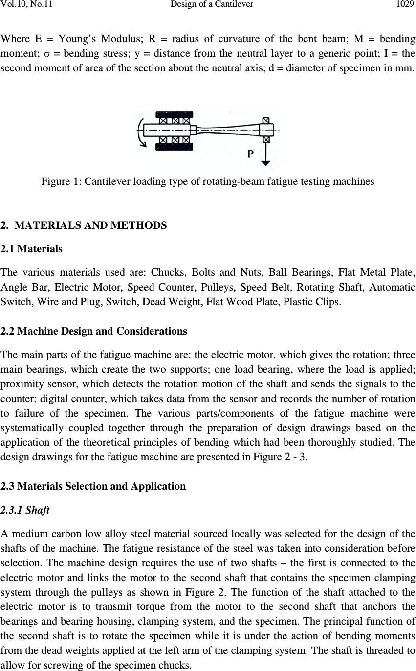 Vol.10, No.11 Where E = Young’s Modulus; R = radius of moment; σ = bending stress; y = distance from the neutral layer to a generic point; I = the second moment of area of the section about the neutral axis Figure 1: Cantilever loading 2. MATERIALS AND METHODS 2.1 Materials The various materials used are: Angle Bar, Electric Motor, Speed Counter, Pulleys, Speed Switch, Wire and Plug, Switch, Dead Weight, Flat Wood Plate, Plastic Clips. 2.2 Machine Design and Considerations The main parts of the fatigue machine main bearings, which create the two supports; proximity sensor, which detects the rotation motion of the shaft and sends counter; digital counter, which takes to failure of the specimen. The various parts/components of the fatigue machine were systematically coupled together through the preparation of design drawings application of the theoret ical principles of bending which had been thoroughly studied design drawings for the fatigue machine 2.3 Materials Selection and Application 2.3.1 Shaft A medium carbon low alloy steel material sourced locally was shafts of the machine. The fatigue resistance of the steel was taken into consideration before selection. The machine design requires the use of two shafts electric motor and links the motor to system through the pulleys as shown in Figure 2. The function of the shaft attached to the electric motor is to transmit torque from the motor to the second shaft that anchors the bearings and bearing h ousing, clamping system, and the specimen. The principal function of the second shaft is to rotate the specimen while it is under the action of bending moments from the dead weights applied at the left arm of the clamping system. The shaft is threaded to a llow for screwing of the specimen chucks. Vol.10, No.11 Design of a Cantilever Where E = Young’s Modulus; R = radius of curvature of the bent beam; M = bending = bending stress; y = distance from the neutral layer to a generic point; I = the second moment of area of the section about the neutral axis ; d = diameter of specimen in Cantilever loading type of rotating- beam fatigue testing machines MATERIALS AND METHODS The various materials used are: Chucks, Bolts and Nuts, Ball Bearings, Flat Metal Plate, Angle Bar, Electric Motor, Speed Counter, Pulleys, Speed Belt, Rotating Shaft, Automatic Wire and Plug, Switch, Dead Weight, Flat Wood Plate, Plastic Clips. Machine Design and Considerations parts of the fatigue machine are: the electric motor , which gives the rotation; three main bearings, which create the two supports; o ne load bearing, where the load is applied sensor, which detects the rotation motion of the shaft and sends the takes data from the sensor and records the number of rotation The various parts/components of the fatigue machine were together through the preparation of design drawings ical principles of bending which had been thoroughly studied design drawings for the fatigue machine are presented in Figure 2 - 3. Materials Selection and Application A medium carbon low alloy steel material sourced locally was selected for the design of the shafts of the machine. The fatigue resistance of the steel was taken into consideration before selection. The machine design requires the use of two shafts – the first is connected to the electric motor and links the motor to the second shaft that contains the specimen clamping system through the pulleys as shown in Figure 2. The function of the shaft attached to the electric motor is to transmit torque from the motor to the second shaft that anchors the ousing, clamping system, and the specimen. The principal function of the second shaft is to rotate the specimen while it is under the action of bending moments from the dead weights applied at the left arm of the clamping system. The shaft is threaded to llow for screwing of the specimen chucks. 1029 curvature of the bent beam; M = bending = bending stress; y = distance from the neutral layer to a generic point; I = the of specimen in mm. beam fatigue testing machines Flat Metal Plate, Belt, Rotating Shaft, Automatic , which gives the rotation; three ne load bearing, where the load is applied ; the signals to the data from the sensor and records the number of rotation The various parts/components of the fatigue machine were based on the ical principles of bending which had been thoroughly studied . The selected for the design of the shafts of the machine. The fatigue resistance of the steel was taken into consideration before the first is connected to the the second shaft that contains the specimen clamping system through the pulleys as shown in Figure 2. The function of the shaft attached to the electric motor is to transmit torque from the motor to the second shaft that anchors the ousing, clamping system, and the specimen. The principal function of the second shaft is to rotate the specimen while it is under the action of bending moments from the dead weights applied at the left arm of the clamping system. The shaft is threaded to  1030 K. K. Alaneme Vol.10, No.11 Figure 2: Fatigue Testing Machine without Casing Figure 3: First Angle Projection of the Fatigue Testing Machine without Covering 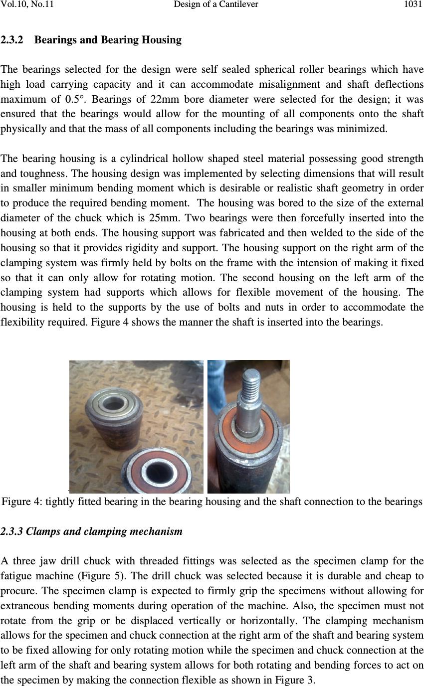 Vol.10, No.11 Design of a Cantilever 1031 2.3.2 Bearings and Bearing Housing The bearings selected for the design were self sealed spherical roller bearings which have high load carrying capacity and it can accommodate misalignment and shaft deflections maximum of 0.5°. Bearings of 22mm bore diameter were selected for the design; it was ensured that the bearings would allow for the mounting of all components onto the shaft physically and that the mass of all components including the bearings was minimized. The bearing housing is a cylindrical hollow shaped steel material possessing good strength and toughness. The housing design was implemented by selecting dimensions that will result in smaller minimum bending moment which is desirable or realistic shaft geometry in order to produce the required bending moment. The housing was bored to the size of the external diameter of the chuck which is 25mm. Two bearings were then forcefully inserted into the housing at both ends. The housing support was fabricated and then welded to the side of the housing so that it provides rigidity and support. The housing support on the right arm of the clamping system was firmly held by bolts on the frame with the intension of making it fixed so that it can only allow for rotating motion. The second housing on the left arm of the clamping system had supports which allows for flexible movement of the housing. The housing is held to the supports by the use of bolts and nuts in order to accommodate the flexibility required. Figure 4 shows the manner the shaft is inserted into the bearings. Figure 4: tightly fitted bearing in the bearing housing and the shaft connection to the bearings 2.3.3 Clamps and clamping mechanism A three jaw drill chuck with threaded fittings was selected as the specimen clamp for the fatigue machine (Figure 5). The drill chuck was selected because it is durable and cheap to procure. The specimen clamp is expected to firmly grip the specimens without allowing for extraneous bending moments during operation of the machine. Also, the specimen must not rotate from the grip or be displaced vertically or horizontally. The clamping mechanism allows for the specimen and chuck connection at the right arm of the shaft and bearing system to be fixed allowing for only rotating motion while the specimen and chuck connection at the left arm of the shaft and bearing system allows for both rotating and bending forces to act on the specimen by making the connection flexible as shown in Figure 3.  1032 K. K. Alaneme Vol.10, No.11 Figure 5: Drill chuck 2.3.4 Proximity sensor The proximity sensor utilized in the design is presented in Figure 6. The sensor is utilized to detect the oscillation of nearby objects without having any physical contact with the object; so far the objects are not more than a distance of 15mm from it. A proximity sensor often emits an electromagnetic or electrostatic field, or a beam of electromagnetic radiation (infrared, for instance), and looks for changes in the field or return signal. It has been found suitable for detecting the number of revolutions of rotating materials hence it was selected to detect the number of revolutions of the shaft under the applied bending moments leading to fatigue failure. The sensor was placed on the end of the shaft at the left arm of the main frame of the machine to detect every cycle the shaft rotates. The rotating motion of the shaft and sends signal to the counter. Figure 6: Proximity Sensor 2.3.5 Digital counter A 6 digit digital counter was selected for recording the number of stress cycles a specimen undergoes during testing. It was ensured that the digital counter was compatible with the proximity sensor selected, that is, it should be able to translate the signals from the sensor to a numerical output. The digital counter utilized can relay digital outputs, but can be programmed to run for a specified number of cyclic revolutions utilizing an analog input bottom incorporated into the counter (Figure 7). It can also be programmed to evaluate rate in 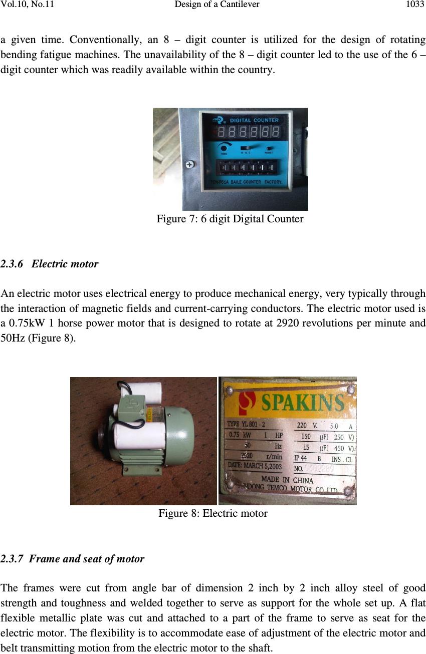 Vol.10, No.11 Design of a Cantilever 1033 a given time. Conventionally, an 8 – digit counter is utilized for the design of rotating bending fatigue machines. The unavailability of the 8 – digit counter led to the use of the 6 – digit counter which was readily available within the country. Figure 7: 6 digit Digital Counter 2.3.6 Electric motor An electric motor uses electrical energy to produce mechanical energy, very typically through the interaction of magnetic fields and current-carrying conductors. The electric motor used is a 0.75kW 1 horse power motor that is designed to rotate at 2920 revolutions per minute and 50Hz (Figure 8). Figure 8: Electric motor 2.3.7 Frame and seat of motor The frames were cut from angle bar of dimension 2 inch by 2 inch alloy steel of good strength and toughness and welded together to serve as support for the whole set up. A flat flexible metallic plate was cut and attached to a part of the frame to serve as seat for the electric motor. The flexibility is to accommodate ease of adjustment of the electric motor and belt transmitting motion from the electric motor to the shaft.  1034 K. K. Alaneme Vol.10, No.11 2.3.8 Electrical connections and circuit diagrams The electrical connection is done in such a way that when the whole machine is put on, the counter comes on and is indicated by the lighting of a bulb but the whole machine doesn’t come on not until the second switch is put on, this is to ensure safety and to be able to control the whole machine. The electrical connection diagram is presented in Figure 9. No Component 1 Bulb Indicator for Electric Motor 2 Electric Motor 3 Bulb Indicator for Speed Counter 4 Speed Counter Figure 9: Electrical connection diagram 2.4 Assembly The different fabricated and purchased part are then assembled together to form the required setup as shown in the design. This starts by passing the turned shaft through the bearing in the housing forcefully and the shaft is allowed to extend beyond the bearing housing. A pulley is fixed to the electric motor and another to the extended shaft of the fixed bearing housing. The electric motor is then securely fastened to its seat and properly aligned with the upper pulley. The chuck is then screwed to the threaded mouth of the shaft and the two bearing housing are tightly screwed to the wooden base and properly aligned with each other. Finishing operation involves the addition of body fillers and grinding of all the parts of the machine using emery papers to make sure the parts are smooth. Thereafter, spraying of the machine was performed and the wooden coverings attached. The resulting work at different stages of finishing is presented in Figures 10 – 12. 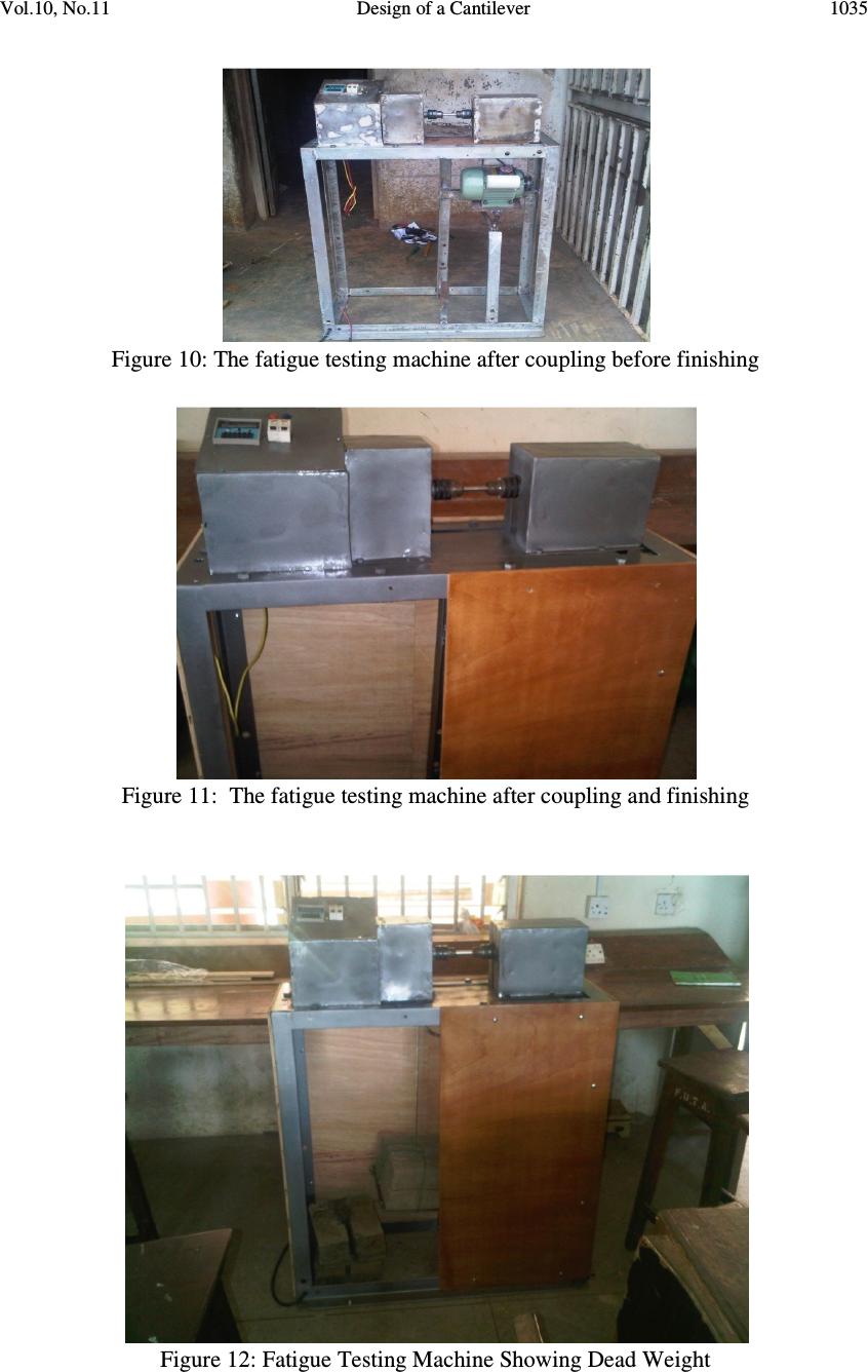 Vol.10, No.11 Design of a Cantilever 1035 Figure 10: The fatigue testing machine after coupling before finishing Figure 11: The fatigue testing machine after coupling and finishing Figure 12: Fatigue Testing Machine Showing Dead Weight  1036 K. K. Alaneme Vol.10, No.11 2.5 Control of the Machine The machine is controlled by two switches; one switch turns on the whole system while the other puts on the electric motor which eventually starts the whole experiment. The magnitude of the load used for testing is predetermined and is applied through the loading arm of the fatigue machine. The bending moment on the specimen and the bending stress are calculated using the relevant relations as discussed in section 1.1. The number of cycles to achieve failure is recorded on the digital counter. The electric motor operates at a constant speed of 2920 rev/min and a frequency of 50Hz. The revolution counting can be achieved with precision by ensuring that the distance between the proximity sensor and the rotating shaft does not exceed 15mm. This will imply regular check after each operation of the machine. 2.6 Testing Mild steel of predetermined chemical composition was utilized to prepare specimens for the fatigue test. The reason for selection of mild steel is that there are well documented stress life fatigue data on mild steel available in literatures. The specimens were machined having a total length of 80mm with 15mm at both ends of the specimen to be held in the chuck so that the length experiencing tension-compression (gauge length) is 50mm. The diameter of the specimen is 12mm while the neck diameter is 8mm. The typical fatigue specimen configuration with dimensions is presented in Figure 13. Figure 13: representative specimen dimensions The machined samples were mounted on the chucks of the machine. The distance from the neck to the specimen’s contact surface with the bearing was measured. The concrete weight was then applied. The revolution counter was set to zero and the electric motor switch turned on. The test terminates once the specimen fractures; after which the electric motor is witched off.  Vol.10, No.11 Design of a Cantilever 1037 3. RESULTS AND DISCUSSION 3.1 Machine Performance The machine enables the evaluation of the stress life fatigue behavior of the tested material through the plotting of bending stress against number of cycles from which the fatigue limit/fatigue strength of the test material can be determined. The working principle of the fatigue machine is easy to learn hence the operation of the machine does not require any specialized training. Following a few simple instructions on the instruction manual and placing the sample in between clamps/chucks, then turning on the switches, gets the machine running. The duration of testing is comparable to that of conventional rotating bending fatigue machines which have an electric motor that operates at 2920 rev/min and 50Hz.Similar machines take approximately 56 hours to achieve 10 7 cycles. The machine during testing was observed to be safe to operate as the whole set up was tightly secured to the base. When testing is to be performed thorough care is taken to ensure that the specimens are tightly clamped in the chuck to safeguard against removal of specimen when the machine is in operation. This ensures that when fracture occurs, the specimen will still be firmly held by the chucks of the machine. The machine was also properly earthed to prevent shock in case of a short circuit. The maintenance strategy to ensure that the machine performs at high efficiency is quite simple. The wires of the machine are properly protected against mutilation by domestic rodents. The proximity sensor is regularly checked to ensure that the maximum distance for reliable sensing of the shaft rotation is not exceeded; also regular cleaning of the sensor particularly if the machine has been unused for some time. In the case of machine malfunction, all parts are easily detachable and to be repaired. 3.2 Cost Analysis The entire materials and equipment used for the design of the fatigue machine are presented in Table 1. The materials and equipment used in the design are locally sourced, and the overall cost of designing the machine is approximately 171,000 Naira ($1100.00). The machine is cheap in comparison to similar designs from abroad. 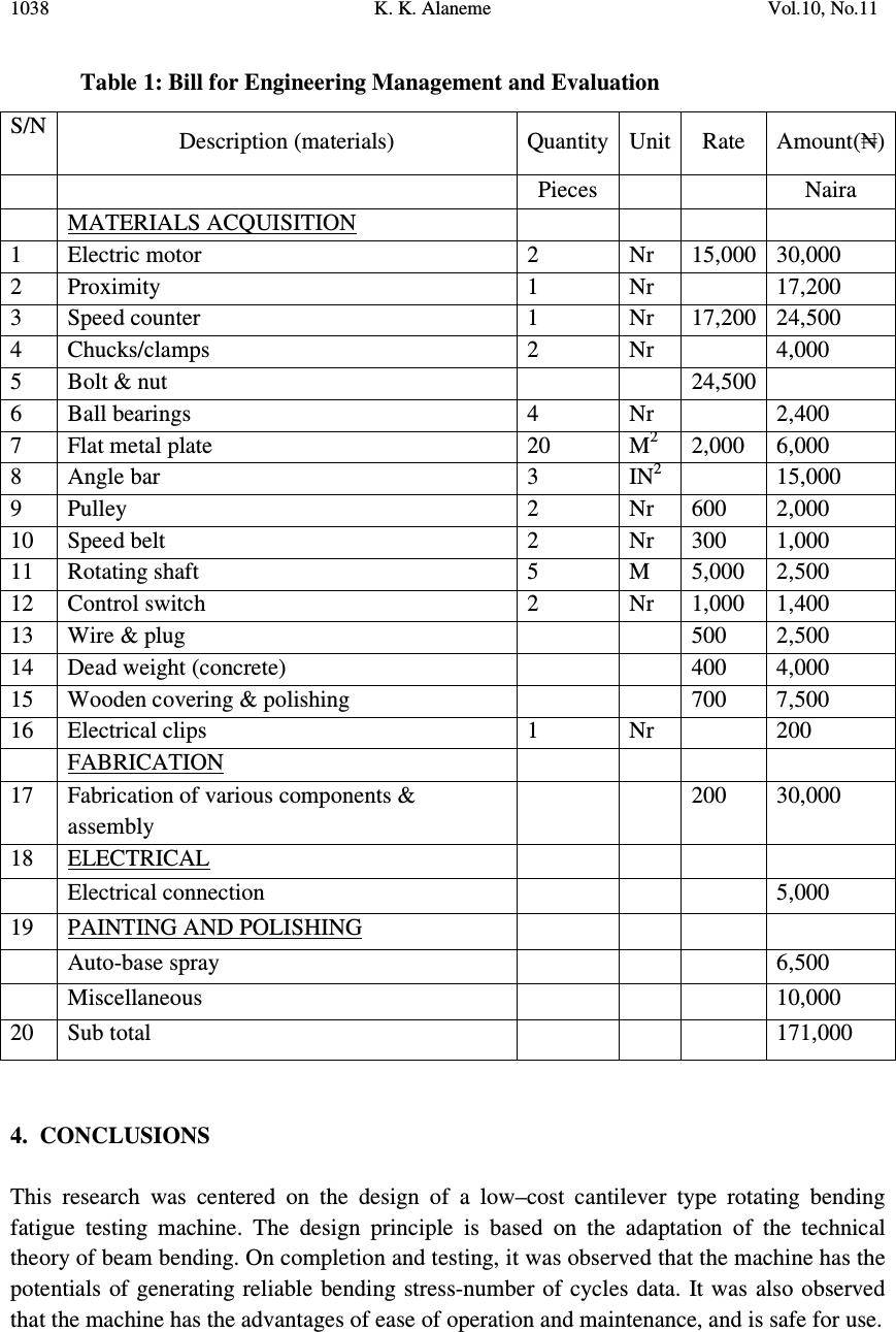 1038 K. K. Alaneme Vol.10, No.11 Table 1: Bill for Engineering Management and Evaluation 4. CONCLUSIONS This research was centered on the design of a low–cost cantilever type rotating bending fatigue testing machine. The design principle is based on the adaptation of the technical theory of beam bending. On completion and testing, it was observed that the machine has the potentials of generating reliable bending stress-number of cycles data. It was also observed that the machine has the advantages of ease of operation and maintenance, and is safe for use. S/N Description (materials) Quantity Unit Rate Amount( ₦ ) Pieces Naira MATERIALS ACQUISITION 1 Electric motor 2 Nr 15,000 30,000 2 Proximity 1 Nr 17,200 3 Speed counter 1 Nr 17,200 24,500 4 Chucks/clamps 2 Nr 4,000 5 Bolt & nut 24,500 6 Ball bearings 4 Nr 2,400 7 Flat metal plate 20 M 2 2,000 6,000 8 Angle bar 3 IN 2 15,000 9 Pulley 2 Nr 600 2,000 10 Speed belt 2 Nr 300 1,000 11 Rotating shaft 5 M 5,000 2,500 12 Control switch 2 Nr 1,000 1,400 13 Wire & plug 500 2,500 14 Dead weight (concrete) 400 4,000 15 Wooden covering & polishing 700 7,500 16 Electrical clips 1 Nr 200 FABRICATION 17 Fabrication of various components & assembly 200 30,000 18 ELECTRICAL Electrical connection 5,000 19 PAINTING AND POLISHING Auto-base spray 6,500 Miscellaneous 10,000 20 Sub total 171,000  Vol.10, No.11 Design of a Cantilever 1039 ACKNOWLEDGEMENT The author appreciates the support of the Association of Commonwealth Universities (ACU) for the award of its Wington Titular Fellowship in Engineering which he utilized at the Materials Engineering Department Indian Institute of Science, Bangalore. The support received from Prof U Ramamurty at whose laboratory the author worked with various types of fatigue machines is immensely appreciated. The author equally recognizes the assistance of Adesheyoju P. A., Afolabi B. M., Oguntimehin J. O and Oke S.R.; in materials sourcing and the fabrication process. REFERENCES [1] J. Rosler, H. Harders, M. Baker, Mechanical Behaviour of Engineering Materials – Metals, Ceramics, Polymers, and Composites, Springer, Germany, 2007, pp 333 – 375. [2] W. Soboyejo, Mechanical Property of Materials, Princeton University, USA, 2002, pp 468-480. [3] K. K. Alaneme, S. M. Hong, Indrani Sen, E. Fleury, and U. Ramamurty, Effect of Copper Addition on the Fracture and Fatigue Crack Growth Behaviour of Solution Heat-Treated SUS 304H Austenitic Steel, Materials Science and Engineering: A 2010, 527: 4600 – 4604. [4] M. Topic, R. B. Tait, C. Allen, The Fatigue Behaviour of metastable (AISI – 304) Austenitic Stainless Steel Wires, International Journal of Fatigue, 2007, 29: 656 – 665. [5] Y. Akiniwa, S. Stanzl –Tschegg, H. Mayer, M. Wakita, and K. Tanaka, Fatigue Strength of Spring Steel under Axial and Torsional Loading in the very High Cycle Regime, International Journal of Fatigue, 2008, 30: 2057 – 2063. [6] D. Brandolisio, G. Poelman, G. De Corte, J. Symynck, M. Juwet, and F. De Bal, Rotating Bending Machine for High Cycle Fatigue Testing, Department of Mechanical Engineering, KaHo Technological University Sint-Lieven Ghent, Belgium, 2007. [7] ASTM E 9 - 99. Manual on fatigue testing. In : Annual Book of ASTM Standards, ASTM International, 1999. [8] J. Hannah, and M. J. Hillier, Applied Mechanics, Third Edition, Longman, England, 1999, pp 341 – 372. [9] N. H. Cook, Mechanics and Materials for Design, Mc Graw – Hill International Edition, Singapore, 1987, pp 238 – 255. |

