Paper Menu >>
Journal Menu >>
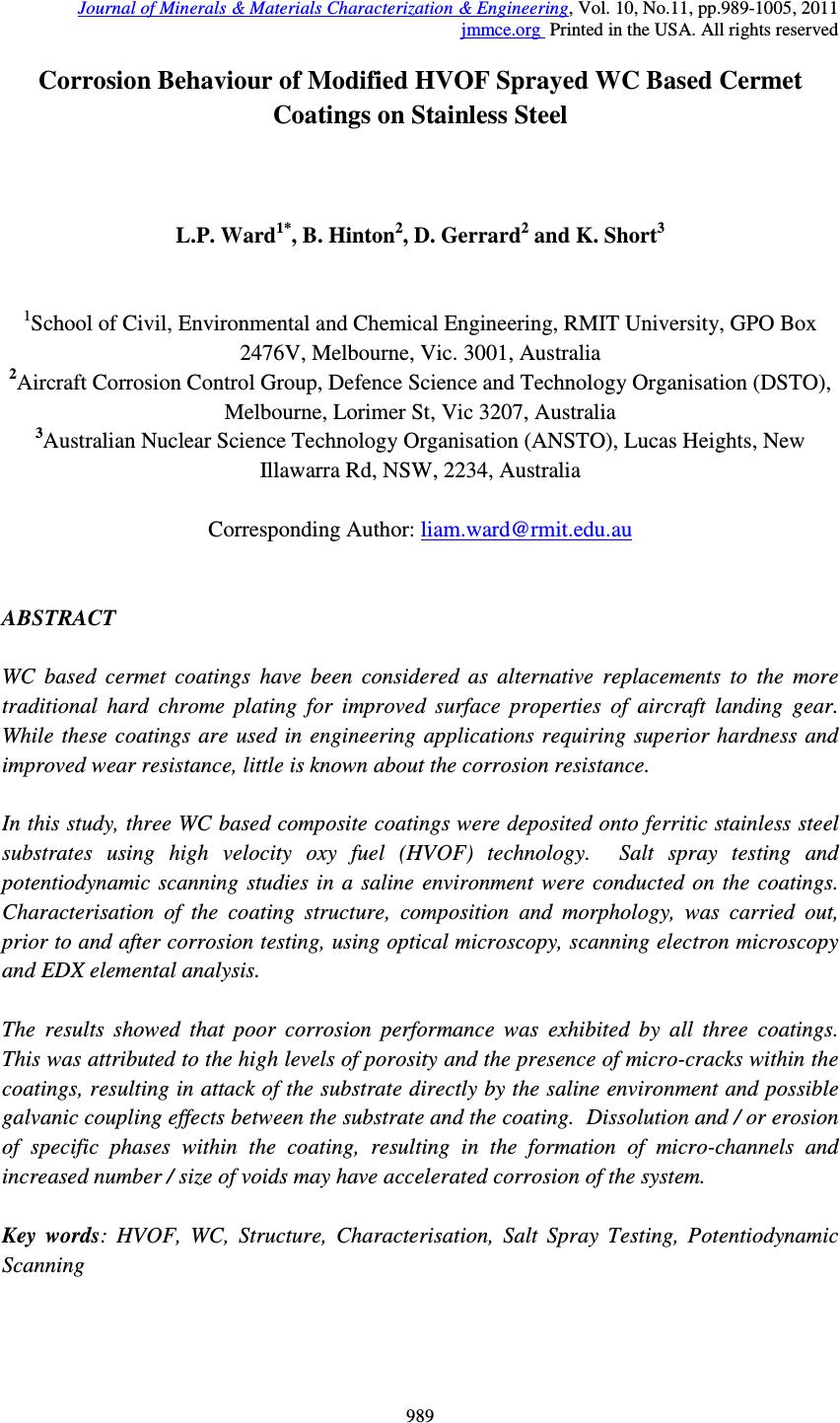 Journal of Minerals & Materials Characterization & Engineering, Vol. 10, No.11, pp.989-1005, 2011 jmmce.org Printed in the USA. All rights reserved 989 Corrosion Behaviour of Modified HVOF Sprayed WC Based Cermet Coatings on Stainless Steel L.P. Ward 1* , B. Hinton 2 , D. Gerrard 2 and K. Short 3 1 School of Civil, Environmental and Chemical Engineering, RMIT University, GPO Box 2476V, Melbourne, Vic. 3001, Australia 2 Aircraft Corrosion Control Group, Defence Science and Technology Organisation (DSTO), Melbourne, Lorimer St, Vic 3207, Australia 3 Australian Nuclear Science Technology Organisation (ANSTO), Lucas Heights, New Illawarra Rd, NSW, 2234, Australia Corresponding Author: liam.ward@rmit.edu.au ABSTRACT WC based cermet coatings have been considered as alternative replacements to the more traditional hard chrome plating for improved surface properties of aircraft landing gear. While these coatings are used in engineering applications requiring superior hardness and improved wear resistance, little is known about the corrosion resistance. In this study, three WC based composite coatings were deposited onto ferritic stainless steel substrates using high velocity oxy fuel (HVOF) technology. Salt spray testing and potentiodynamic scanning studies in a saline environment were conducted on the coatings. Characterisation of the coating structure, composition and morphology, was carried out, prior to and after corrosion testing, using optical microscopy, scanning electron microscopy and EDX elemental analysis. The results showed that poor corrosion performance was exhibited by all three coatings. This was attributed to the high levels of porosity and the presence of micro-cracks within the coatings, resulting in attack of the substrate directly by the saline environment and possible galvanic coupling effects between the substrate and the coating. Dissolution and / or erosion of specific phases within the coating, resulting in the formation of micro-channels and increased number / size of voids may have accelerated corrosion of the system. Key words: HVOF, WC, Structure, Characterisation, Salt Spray Testing, Potentiodynamic Scanning  990 L.P. Ward, B. Hinton, D. Gerrard and K. Short Vol.10, No.11 1. INTRODUCTION For many years corrosion protection of structural aircraft components such as the landing gear, has been achieved with the deposition of a hard chrome electroplated coating. Hard chrome plating provides a combination of good surface hardness, wear resistance and adequate corrosion resistance. However, the carcinogenic effects of hexavalent chromium salts associated with the plating process, has stimulated research into the use of “cleaner technology” methods for coating production, as alternatives to chrome plating. One such group of coatings of considerable interest are thermally sprayed WC based ceramic / metal composite coatings. These coatings are selected primarily for applications requiring enhanced wear resistance and surface hardness, and to a lesser extent, their corrosion resistance. Studies on the behaviour of HVOF deposited WC coatings by Nascimento et al [1] showed poor corrosion resistance, results being similar to those obtained for hard chromium electroplated coatings, even though improved fatigue and abrasive wear characteristics were observed. However, improved corrosion resistance was observed when metallic and other binders were incorporated within the WC based matrix. Superior corrosion resistance for HVOF sprayed WC – Co coatings on steel compared with electroplated hard chrome coatings after long term atmospheric corrosion testing has been reported [1-3] and further improvements, when exposed to seawater, were observed by Perry et al [4] when Cr was added to the WC - Co based coating’s matrix. Reduced porosity with increasing levels of Co binder, observed by Saenger et al [5] may be responsible for increased resistance. Significant improvement in the corrosion behaviour of HVOF WC-Co coatings was observed after modifying the coating composition with additions of NiCrAl and / or conducting a post melt treatment [6]. Corrosion studies conducted by Lekatou et al on WC-17Co coatings in both 0.5 M H 2 SO 4 [7] and 3.5% aqueous NaCl [8] revealed that active corrosion processes were induced as a result of an inhomogeneous binder comprising of a Co(W,C) matrix with varying composition. Active dissolution of the binder phase (Co) initially occurred during anodic polarisation in 0.5 M H 2 SO 4 [7] In addition, potentiodynamic scans conducted in both solutions revealed pseudopassivity was observed, which was thought to be associated with oxidation of the W, Co and C. A comparison of the electrochemical corrosion resistance of HVOF sprayed WC- 17%Co and WC-17%Ni using polarisation and electro-impedance spectroscopy studies [9] revealed that the improved corrosion behaviour associated with the WC-17Ni coating was attributed to a combination of lower porosity of these coatings and better corrosion resistance of the Ni binder, when deposited on mild steel substrates. Similar observations have been reported for bulk WC-Ni composites and attributed to the corrosion resistant nature of the Ni binder [10]. The electrochemical corrosion behaviour of HVOF sprayed Cr 3 C 2 –NiCr and WC–Ni coatings under different process conditions using potentiodynamic scanning and EIS were studied by Espallargas et al [11]. The results showed that the Cr 3 C 2 –NiCr coatings showed superior  Vol.10, No.11 Corrosion Behaviour of Modified HVOF 991 corrosion resistance compared with the WC-Ni coatings, making them a good alternative to conventional hard chrome coatings. Studies on the effect of post laser treatment on the corrosion properties of HVOF WC based coatings [12, 13] revealed improved corrosion resistance after laser treatment. Such improvement was attributed to a number of factors, to include reduction in the size and number of pores / microcavities formed [12, 13], elimination of the formation of a discrete splat-structure [12], the formation of a compact interface [13] and a reduced microgalvanic driving force between the WC and the metal matrix [12]. Differences in the corrosion behaviour of HVOF thermally sprayed WC coatings with a selection metallic binders were attributed to variations in the galvanic effects induced between the WC phase and various metallic binder [14]. Here, enhanced corrosion was associated with binder materials showing more anodic characteristics. In contrast, electrochemical corrosion tests conducted by Koon et al [15] revealed that corrosion rate values were much higher for WC-Co-Cr and WC-CrC-Ni coatings, compared with hard chrome coated stainless steel samples and stainless steel itself. The literature has shown that while it is suggested that the use of binder materials with WC may improve the corrosion resistance, this is dependant on the composition of the binder material and that the results on their behaviour are conflicting. The purpose of this study was to systematically investigate the corrosion behaviour of a series of HVOF sprayed WC based composite coatings deposited on stainless steel, using standard salt spray testing and electrochemical potentiodynamic scanning studies. 2. EXPERIMENTAL Rectangular plate 409 ferritic stainless steel specimens were sectioned from 2 mm thick sheet, having dimensions 150 mm X 100 mm. Samples were shot blasted and degreased in alcohol to remove any surface contaminants, prior to coating. Three modified WC based cermet coatings were deposited onto the stainless steel plates using commercially available high velocity oxygen fuel (HVOF) spraying facilities. Coatings, having thicknesses in the range 250 – 300 µm, were of the type WC-12Ni, WC-20Cr 2 C 3 -7Ni and WC-10Co-4Cr. No information was available about the specific spraying parameters (distribution and size of powder feedstock, relative amounts, spraying velocity, etc), due to the proprietary nature of the commercial process. The corrosion behaviour of the WC based coatings was determined using salt spray (fog) testing and electrochemical potential-current density (potentiodynamic scanning) measurements. All salt spray (fog) tests were carried out in accordance with ASTM B 117 standards [16]. Prior to insertion into the salt spray cabinet, samples were degreased in MEK. Samples were inclined at a 45º angle, coating side upward, which were exposed to a salt fog produced from 5% NaCl solution, with pH range from 6.5 to 7.2. The temperature of the  992 L.P. Ward, B. Hinton, D. Gerrard and K. Short Vol.10, No.11 chamber was maintained constant at 35ºC. Exposure times for coated samples ranged from between 19 hours up to 558 hours. Samples were removed periodically from the chamber for visual inspection and microscopy analysis. Potentiodynamic scanning studies on coated and uncoated samples were conducted using a Potentiostat. A conventional three - electrode cell set up consisting of the working electrode, a saturated calomel electrode as the reference electrode and a platinum counter electrode was used. Analysis of the results was achieved using the software Corrview. All tests were carried out in 0.6 M sodium chloride (NaCl) solution at room temperature (23ºC). Here, samples were scanned in the range -1200 mV to +200 mV in order to obtain full anodic and cathodic polarisation curves. The results were presented as polarisation curves in the form E vs. log I plots. The corrosion potential E corr and the corrosion current I corr were determined by the Tafel extrapolation method. Characterisation of the coatings surface and cross section, prior to and after salt spray testing, was carried out using optical microscopy and scanning electron microscopy in conjunction with EDX analysis. 3. RESULTS AND DISCUSSION 3.1 Structural Characterisation of the As Sprayed Coatings Optical micrograph of the WC-12Ni, WC-20Cr 2 C 3 -7Ni and WC-10CoO-4Cr coating in cross section are shown in Figs. 1 to 3 respectively. The coating thickness measured in this region varied between 242 and 275 µm for WC-12Ni coating. Similar thicknesses were observed for the WC-10Co-4Cr coating (typically in the range 261 to 286 µm); however the WC- 20Cr 2 C 3 -7Ni coatings were much thinner, with coating thickness varying from 128 to 150 µm. Fig. 1 Optical micrograph of WC-12Ni coating cross section 275 µ µµ µm 256 µ µµ µm 242 µ µµ µm 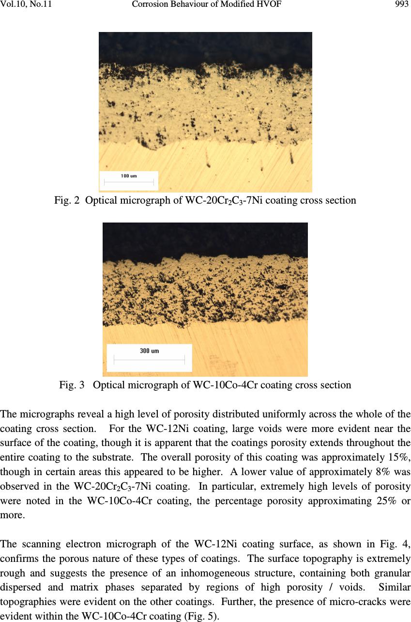 Vol.10, No.11 Corrosion Behaviour of Modified HVOF 993 Fig. 2 Optical micrograph of WC-20Cr 2 C 3 -7Ni coating cross section Fig. 3 Optical micrograph of WC-10Co-4Cr coating cross section The micrographs reveal a high level of porosity distributed uniformly across the whole of the coating cross section. For the WC-12Ni coating, large voids were more evident near the surface of the coating, though it is apparent that the coatings porosity extends throughout the entire coating to the substrate. The overall porosity of this coating was approximately 15%, though in certain areas this appeared to be higher. A lower value of approximately 8% was observed in the WC-20Cr 2 C 3 -7Ni coating. In particular, extremely high levels of porosity were noted in the WC-10Co-4Cr coating, the percentage porosity approximating 25% or more. The scanning electron micrograph of the WC-12Ni coating surface, as shown in Fig. 4, confirms the porous nature of these types of coatings. The surface topography is extremely rough and suggests the presence of an inhomogeneous structure, containing both granular dispersed and matrix phases separated by regions of high porosity / voids. Similar topographies were evident on the other coatings. Further, the presence of micro-cracks were evident within the WC-10Co-4Cr coating (Fig. 5). 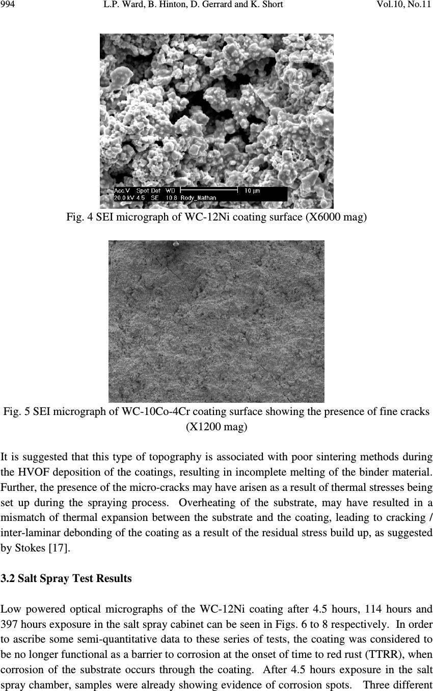 994 L.P. Ward, B. Hinton, D. Gerrard and K. Short Vol.10, No.11 Fig. 4 SEI micrograph of WC-12Ni coating surface (X6000 mag) Fig. 5 SEI micrograph of WC-10Co-4Cr coating surface showing the presence of fine cracks (X1200 mag) It is suggested that this type of topography is associated with poor sintering methods during the HVOF deposition of the coatings, resulting in incomplete melting of the binder material. Further, the presence of the micro-cracks may have arisen as a result of thermal stresses being set up during the spraying process. Overheating of the substrate, may have resulted in a mismatch of thermal expansion between the substrate and the coating, leading to cracking / inter-laminar debonding of the coating as a result of the residual stress build up, as suggested by Stokes [17]. 3.2 Salt Spray Test Results Low powered optical micrographs of the WC-12Ni coating after 4.5 hours, 114 hours and 397 hours exposure in the salt spray cabinet can be seen in Figs. 6 to 8 respectively. In order to ascribe some semi-quantitative data to these series of tests, the coating was considered to be no longer functional as a barrier to corrosion at the onset of time to red rust (TTRR), when corrosion of the substrate occurs through the coating. After 4.5 hours exposure in the salt spray chamber, samples were already showing evidence of corrosion spots. Three different 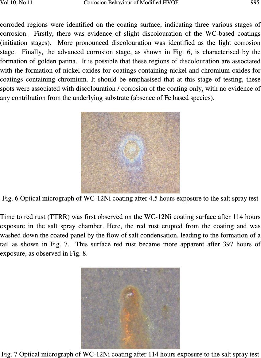 Vol.10, No.11 Corrosion Behaviour of Modified HVOF 995 corroded regions were identified on the coating surface, indicating three various stages of corrosion. Firstly, there was evidence of slight discolouration of the WC-based coatings (initiation stages). More pronounced discolouration was identified as the light corrosion stage. Finally, the advanced corrosion stage, as shown in Fig. 6, is characterised by the formation of golden patina. It is possible that these regions of discolouration are associated with the formation of nickel oxides for coatings containing nickel and chromium oxides for coatings containing chromium. It should be emphasised that at this stage of testing, these spots were associated with discolouration / corrosion of the coating only, with no evidence of any contribution from the underlying substrate (absence of Fe based species). Fig. 6 Optical micrograph of WC-12Ni coating after 4.5 hours exposure to the salt spray test Time to red rust (TTRR) was first observed on the WC-12Ni coating surface after 114 hours exposure in the salt spray chamber. Here, the red rust erupted from the coating and was washed down the coated panel by the flow of salt condensation, leading to the formation of a tail as shown in Fig. 7. This surface red rust became more apparent after 397 hours of exposure, as observed in Fig. 8. Fig. 7 Optical micrograph of WC-12Ni coating after 114 hours exposure to the salt spray test 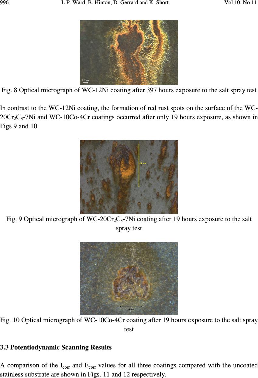 996 L.P. Ward, B. Hinton, D. Gerrard and K. Short Vol.10, No.11 Fig. 8 Optical micrograph of WC-12Ni coating after 397 hours exposure to the salt spray test In contrast to the WC-12Ni coating, the formation of red rust spots on the surface of the WC- 20Cr 2 C 3 -7Ni and WC-10Co-4Cr coatings occurred after only 19 hours exposure, as shown in Figs 9 and 10. Fig. 9 Optical micrograph of WC-20Cr 2 C 3 -7Ni coating after 19 hours exposure to the salt spray test Fig. 10 Optical micrograph of WC-10Co-4Cr coating after 19 hours exposure to the salt spray test 3.3 Potentiodynamic Scanning Results A comparison of the I corr and E corr values for all three coatings compared with the uncoated stainless substrate are shown in Figs. 11 and 12 respectively.  Vol.10, No.11 Corrosion Behaviour of Modified HVOF 997 Icorr Values for WC Composite Coatings on Stainless Steel 0 50 100 150 200 250 Stainless SteelWC-12NiWC-20Cr2C3- 7Ni WC-10C0-4Cr Coating type Icorr (microA/sq.cm) Fig. 11 I corr values for HVOF WC based composite coatings deposited on stainless steel Ecorr Values for WC Composite Coatings on Stainless Steel -600 -500 -400 -300 -200 -100 0 Stainless SteelWC-12Ni WC-20Cr2C3- 7Ni WC-10C0-4Cr Coating Type Ecorr (mV) vs SCE Fig. 12 E corr values for HVOF WC based composite coatings deposited on stainless steel All coatings exhibited much higher I corr values (60 µA/cm 2 , 200 µA/cm 2 and 30 µA/cm 2 for WC-12Ni, WC-20Cr 2 C 3 -7Ni and WC-10Co-4Cr respectively) compared with 0.85 µA/cm 2 for uncoated stainless steel. This would suggest that WC-20Cr 2 C 3 -7Ni coatings would be expected to exhibit the highest corrosion rates, followed by WC-12Ni, WC-10Co-4Cr and finally stainless steel showing the lowest corrosion rate. Further, all coatings, displayed more negative E corr values compared with the stainless steel, stainless steel having a value of -260 mV, compared with -520 mV, -390 mV and -440 mV for WC-12Ni, WC-20Cr 2 C 3 -7Ni and WC-10Co-4Cr respectively. A typical E – log I plot for WC-10Co-4Cr deposited on stainless steel is shown in Fig. 13.  998 L.P. Ward, B. Hinton, D. Gerrard and K. Short Vol.10, No.11 10 - 7 10 -6 10 -5 10 - 4 10 -3 10 - 2 -1.5 -1.0 -0.5 0 I (Amps/cm 2 ) E (Volts) Fig. 13 E – Log I plot for WC-10Co-4Cr deposited on stainless steel 3.4 Structural Characterisation of the Corroded Coatings A scanning electron micrograph of the corroded WC-12Ni coating surface and corresponding elemental mapping using EDX analysis are shown in Figs. 14 and 15 respectively. The SEI image indicates cracking occurring between the matrix and binder particles. The elemental maps indicate that, within the coating, a significant amount of Ni and Na were present, and to a lesser extent W, C, Fe, O, Cr and Cl. Within the cracks themselves, reduced amounts of Ni and Na, and to a lesser extent O and Cl, were observed, in addition to increased amounts of W. Analysis of EDX spectra taken from both corroded and uncorroded WC-12Ni coatings confirmed after corrosion, Ni content increased from 14.13 to 26.17 wt% and O content from 0.38 to 23.37 wt%, while a large reduction in the W content from 84.06 to 44.38 wt% was observed. Further, small amounts of Fe (2.38 wt %), Cr (0.07 wt %), Na (2.78 wt %) and Cl (0.9 wt %) were identified on the corroded coating surface [18]. The corroded surface of the WC-20Cr 2 C 3 -7Ni coating, as shown in Fig. 16, shows the presence of quite large micro-cracks, as previously observed in the WC-12Ni coating. It is postulated that the accelerated growth of these cracks, initiated during the spraying process, may have been due to the combined effect of inherent residual stresses and corrosive E corr =-0.44 Volts I corr = 3.0E-5 Amp/cm 2 Anodic Scan Cathodic Scan  Vol.10, No.11 Corrosion Behaviour of Modified HVOF 999 environment, creating a situation analogous to stress corrosion cracking. Further work on stress analysis needs to be carried out to confirm stress levels within the coating. Fig. 14 SEI micrograph of corroded WC-12Ni coating (X 20,000 mag) Fig. 15 EDX elemental maps of corroded WC-12Ni coating in Fig. 14 (X 20,000 mag) Tungsten Carbon (C) Iron (Fe) Nickel (Ni) Chlorine (Cl) Sodium (Na) Chromium (Cr) Oxygen (O 2 ) Selenium  1000 L.P. Ward, B. Hinton, D. Gerrard and K. Short Vol.10, No.11 3.5 Discussion on the Corrosion Behaviour of WC Based Composite Coatings The results from this study indicate that, overall, the (i) poor performance observed from the salt spray studies and (ii) higher I corr values when compared with the base material from the electrochemical studies can be largely attributed to the high degree of porosity / presence of voids and micro-cracks within the coating. It is likely that the coatings contain numerous networks of continuous voids, pores and cracks that extend from the coating surface through to the substrate. Such findings are in agreement with previously studies [14, 19]. The occurrence of red rust spots after 114 hours for the WC-12Ni, and 19 hours for the other coatings, was due to rusting of the stainless steel substrate, due to ingress of the NaCl solution through channels associated with the porosity and voids within the coating, as evidenced in Figs. 9 to 12. In addition, the presence of a network of micro-cracks (Fig. 13), may have also have contributed further to the poor corrosion resistance of the coating as these micro-cracks may have allowed NaCl to seep in through the coating and attack the stainless steel substrate. In particular the enlarged micro-cracks observed on the WC-20Cr 2 C 3 -7Ni coating as shown in Fig. 16 is supported by previous studies (10) which suggested that the overall corrosion resistance of a WC-CrC-Ni coating was inferior to that of a WC-Co-Cr coating due to the presence of micro-cracks acting as infiltration paths for the solution. Such a mechanism may also be responsible for the higher I corr value observed for the WC-20Cr 2 C 3 - 7Ni coating. Fig. 16 SEI micrograph of corroded surface of WC-20Cr 2 C 3 -7Ni showing enlarged micro- cracks The lack of red rust spots on the WC-12Ni coating, prior to 114 hours exposure time was possible due to the fact that stainless steel initially showed high resistance to corrosion and / or the coating was acting as a barrier to corrosion. The onset of time to red rust after only 19 hours for the other two coatings can be attributed to similar mechanisms, accelerated times occurring as a result of the higher levels of porosity for the WC-10CO-4Cr coating and the WC-20Cr 2 C 3 -7Ni coating being much thinner. The observed improvement in the WC-12Ni coating’s resistance to salt spray testing may be due to the presence of the Ni acting as an inert binder, as observed by Aw et al [9]. In addition, the increase in corrosion rates (higher I corr values) and more negative E corr values for the coatings, when compared with the stainless steel, can be attributed to the formation of  Vol.10, No.11 Corrosion Behaviour of Modified HVOF 1001 a galvanic cell resulting in accelerated corrosion of the more active components of the coating system, as observed by Cho et al [14]. It is further suggested that accelerated corrosion of the substrate via voids and cracks may occur due to dissolution of certain phases within the coating, resulting in increased formation of voids and continuous channels through the coating allowing for further ingress of the aggressive medium. The observed significant reduction in the amount of W and increase in the amount of Ni present in the corroded WC-12Ni coating may be attributed to (i) the dissolution of tungsten during salt spray testing and / or (ii) the migration of Ni species at the surface after testing. The significant amounts of both Ni and O within the coating surface, suggest the presence of NiO as a corrosion product. Appreciable levels of Na and to a lesser extent, Cl, confirm the presence of salt residue from the testing. The presence of Fe and Cr species at the surface cannot rule out selective leaching of these species from the base material. Increased levels of W within the cracks, compared to the coating, may give support to the theory of Ni products forming on the surface, thus masking out the W, as opposed to W dissolution. Further characterisation using XRD and other techniques is recommended to confirm the above findings Metallographic cross sections of the corroded WC-10Co-4Cr coating after exposure to salt spray testing are shown in Figs. 17 and 18. It is evident that the increased presence of continuous micro-channels (Fig. 17) and large voids (Fig. 18) occurred during their exposure to the salt spray. Here, the formation of micro-channels and voids can be attributed to both mechanical and chemical effects, whereby (i) dissolution of soluble phases within the coating and / or (ii) erosion of certain phases within the coating may have occurred. Fig. 17 Optical micrograph of corroded WC-10Co-4Cr coating cross section showing the presence of micro channels  1002 L.P. Ward, B. Hinton, D. Gerrard and K. Short Vol.10, No.11 Fig. 18 Optical micrograph of corroded WC-10Co-4Cr coating cross section showing large voids The corroded surface of the WC-10Co-4Cr coating, as shown in Fig. 19, consists of the WC matrix, Co and Cr binders, salt deposits and oxide corrosion products. EDX analysis of the surface revealed an increase in the concentration of Cr (2.9 to 4.0 wt%) and Co (9.4 to 18.7 wt%) and a decrease in the W species (87.3 to 70.2 wt%), when compared with the as sprayed coating. Small amounts of Na and Cl (< 1 wt%) was also recorded. This would suggest, as for the WC-12Ni coating, dissolution of the WC phase, the formation of Co and Cr oxides and deposits of salt on the surface has occurred after exposure to the salt spray. While free energy data predicts the formation of CoO and Cr 2 O 3 and possibly Co(OH) 2 as being the most energetically favoured (having free energies of -212.3, -252.9 and -105.6 kcal/mol respectively), the formation of soluble chloride species, such as CrCl 2 , CrCl 3 and CoCl 2 cannot be discounted as they have negative free energy values of -85.09, -116.18 and - 64.48 kcal/mol respectively. Fig. 19 SEI micrograph of corroded surface of WC-10CO-4Cr While it has been postulated that increased corrosion may occur due to dissolution and / or erosion of phases within the coating, Warsono [18] observed a reduction in the corrosion activities at the sites where the initial formation of red rust spots was observed, resulting in fewer observed changes in the surface appearance with increased exposure time. It is suggested that here, corrosion was reduced due to (i) the build up of corrosion products within the pores and (ii) the corrosion products associated with the stainless steel acting as a protective layer, thus forming a barrier between the salt solution and the stainless steel substrate. Further, the formation of nickel oxide, as evidenced from EDX analysis, revealing significantly higher levels of O and Ni compared with other regions, may have provided  Vol.10, No.11 Corrosion Behaviour of Modified HVOF 1003 additional protection. It has been suggested [20] that a nickel oxide layer can behave as a passive layer, thus protecting the coating from further corrosion. The results of the study here are similar to observations by Nascimento et al [1], for HVOF deposited WC coatings on AISI 4340 high strength steel, who suggested the lack of protection can be attributed to the high content of pores. However, it should be emphasised that the WC-12Ni coating in the current study had not completely corroded after 558 hours exposure, while the WC coating was completely corroded after only 72 hours exposure [1]. This may be attributed to the fact that the high strength steel was less likely to be corrosion resistant compared to the stainless steel. 4. CONCLUSIONS 1. Three WC based composite coatings (WC-12Ni, WC-20Cr 2 C 3 -7Ni and WC-10Co-4Cr) were deposited on 409 ferritic stainless steel substrates using high velocity oxy fuel (HVOF) spraying technology. 2. Salt spray testing revealed extensive corrosion (time to red rust) was observed after 114 hours for the WC-12Ni coating and only 19 hours for both the WC-20Cr 2 C 3 -7Ni and WC- 10Co-4Cr coatings. 3. The poor corrosion performance was attributed to the high levels of porosity and the presence of micro-cracks within the coatings, resulting in attack of the substrate directly by the saline environment. This was possibly due to incomplete sintering between the WC matrix and the binders during the spraying process. 4. Potentiodynamic scanning studies revealed poor corrosion performance of the coatings when compared with the stainless steel substrate, with increased I corr values and more negative E corr values. This was attributed to the poor structure and possible galvanic coupling effects between the substrate and the coating. 5. Corrosion of the coating substrate system may have been accelerated by dissolution and / or erosion of specific phases within the coating, resulting in the formation of micro-channels and increased number / size of voids. 5. RECOMMENDATIONS 1. To deposit coatings with greater variation in the spraying variables in order to systematically study the effect of process parameters on the corrosion behaviour and optimise the system in terms of reduced porosity / enhanced coating integrity 2. To expand the range of corrosion tests to include techniques such as ac impedance in order to further characterise and optimise the coating system  1004 L.P. Ward, B. Hinton, D. Gerrard and K. Short Vol.10, No.11 3. To conduct post deposition treatments (annealing, laser treatment) in order to reduce surface porosity 4. To employ a greater range of characterisation techniques, such as XPS, in order to provide a deeper understanding into the corrosion / active dissolution mechanisms occurring ACKNOWLEDGEMENTS This work was carried out as part of a research collaborative program between RMIT University and Defence, Science and Technology Organisation (DSTO). The authors would like to acknowledge G. Biddle from the Surface Materials Analysis Research & Training Group, Department of Applied Physics RMIT University for conducting the SEM and EDX analysis and F. Sciacca, T. Firouzian and R. Warsono for their contributions to the corrosion studies as part of their undergraduate final year projects. Additionally, the authors would like to acknowledge support provided for part of this overall program by the Australian Institute of Nuclear Science and Engineering (AINSE - grant no. AINGRA04180P). REFERENCES [1] Nascimento, M. P., Souza, R.C., Miguel, I.M, Pigatin, W. L. and Voorwald, H. J. , 2001, “Effects of Tungsten Carbide Thermal Spray Coating by HP/HVOF and Hard Chromium Electroplating on AISI 4340 High Strength Steel”, Surface and Coatings Technology, Vol. 138, pp. 113-124. [2] Natishan, P. M., Lawrence, S. H., Foster, R. L. and Sartwell, B. D., 2002, “Atmospheric Corrosion Study of Electrodeposited Hard Chromium and High-Velocity Oxygen-Fuel Thermal Spray Coatings”, Corrosion, Vol. 58, Ed. 2, pp. 119-123. [3] Sartwell, B. D., 2000, “HVOF Thermal Spray Coatings Replace Hard Chrome: (High- Velocity Oxygen-Fuel)”, Advanced Materials and Processes, Vol. 156, Ed. 2, pp. 25-28. [4] Perry, J. M., Neville A. and Hodgkiess, T., 2002, “A Comparison of the Corrosion Behaviour of WC-Co-Cr and WC-Co HVOF Thermally Sprayed Coatings by In Situ Atomic Force Microscopy (AFM)”, Journal of Thermal Spray Technology, Vol. 11, Ed. 4, pp. 536-541. [5] Saenger, R., Martin, D. and Gabrielli, C., 2005, “Electrochemical Characterisation of Plasma Sprayed WC-Co Coatings by Impedance Techniques”, Surface and Coatings Technology, Vol. 194, pp. 335-343. [6] Godoy, C., Lima, M. M., Castro, M. M. R. and Avelar–Batista, J. C., 2004, “Structural Changes in High Velocity Oxy – Fuel Thermally Sprayed WC-Co Coatings for Improved Corrosion Resistance”, Surface and Coatings Technology, Vol. 188-189, pp. 1-6. [7] Lekatou, A., Regoutas, E. and Karantzalis, A. E., 2008, “Corrosion Behaviour of Cermet Based Coatings with a Bond Coat in 0.5 M H 2 SO 4 ”, Corrosion Science, Vol. 50, pp. 3389-3400.  Vol.10, No.11 Corrosion Behaviour of Modified HVOF 1005 [8] Lekatou, A., Grois, D. and Grimanelis, D., 2008, “Corrosion Properties of HVOF Cermet Coatings with Bond Coats in an Aqueous Chloride Environment), Thin Solid Films, Vol. 516, pp. 5700-5705. [9] Aw, P.K., Tan, A. L. K., Tan, T. P. and Qiu, J., 2008, “Corrosion Resistance of Tungsten Carbide Based Cermet Coatings Deposited by the High Velocity Oxy Fuel Spray Process”, Thin Solid Films, Vol. 516, pp. 5710-5715 [10] Kalish, H. S., 2009, Corrosion of Cemented Carbides, ASM Handbooks on-line, Vol. 13B, Corrosion, < products.asminternational.org>. [11] Espallargas, N., Berget, J., Guilemany J. M., Benedetti, A. V. and Suegama, P. H., 2008, “Cr 3 C 2 –NiCr and WC–Ni Thermal Spray Coatings as Alternatives to Hard Chromium for Erosion–Corrosion Resistance”, Surface & Coatings Technology, Vol. 202, pp. 1405–1417. [12] Liu, Z., Cabrero, J., Niang, S. and Al-Taha, Z. Y, 2007, “Improving Corrosion and Wear Performance of HVOF-Sprayed Inconel 625 and WC-Inconel 625 Coatings by High Power Diode Laser Treatments”, Surface & Coatings Technology, Vol. 201, pp. 7149– 7158. [13] Zhang, S. H., Yoon, J. H., Li, M. X., Cho, T. Y., Joo, Y. K. and Cho, J.Y., 2010, “Influence of CO 2 Laser Heat Treatment on Surface Properties, Electrochemical and Tribological Performance of HVOF Sprayed WC–24%Cr 3 C 2 –6%Ni Coating”, Materials Chemistry and Physics, Vol. 119, pp. 458–464. [14] Cho, J. E., Hwang, S. Y. and Kim, K.Y., 2006, “Corrosion Behaviour of Thermal Sprayed WC Cermet Coatings Having Various Metallic Binders in Strong Acidic Environments, Surface and Coatings Technology, Vol. 200, pp. 2653-2662. [15] Koon, A. P., Hee, T. B., Taylor, M. , Western M. and Yip, J., 1999, Hard Chrome Replacements by HVOF Sprayed Coatings, SIMTech Technical Report (Pt/99/002/ST), Surface Technology Group, Process Technology Division. [16] ASTM Committee, 1997, Standard Practice for Operating Salt Spray (Fog) Apparatus, ASTM Standard Designation: B117 – 97, ASTM, United States. [17] Stokes, J., 2008, The Theory and Application of the HVOF Thermal Spray Process, Dublin City University, ISBN 1-87232-753-2, ISSN 1649-8232 < webpages.dcu.ie/~stokesjt/ThermalSpraying/Book/HVOFThermalSpraying.htm>. [18] Warsono, R., 2004, Development of HVOF Sprayed Tungsten Carbide Nickel Coatings Deposited on Stainless Steel Substrates for Corrosion Protection in the Aerospace Environment, Internal Report, RMIT University, Melbourne. [19] Celik E., Ozdemir, I., Avci, E. and Tsunekawa, Y., 2005, “Corrosion Behaviour of Plasma Sprayed Coatings”, Surface and Coatings Technology, Vol. 193 pp. 297-302. [20] Jones, D.A., 1992, Principles and Prevention of Corrosion, Maxwell Macmillan International Publishing Group, Sydney. |