Paper Menu >>
Journal Menu >>
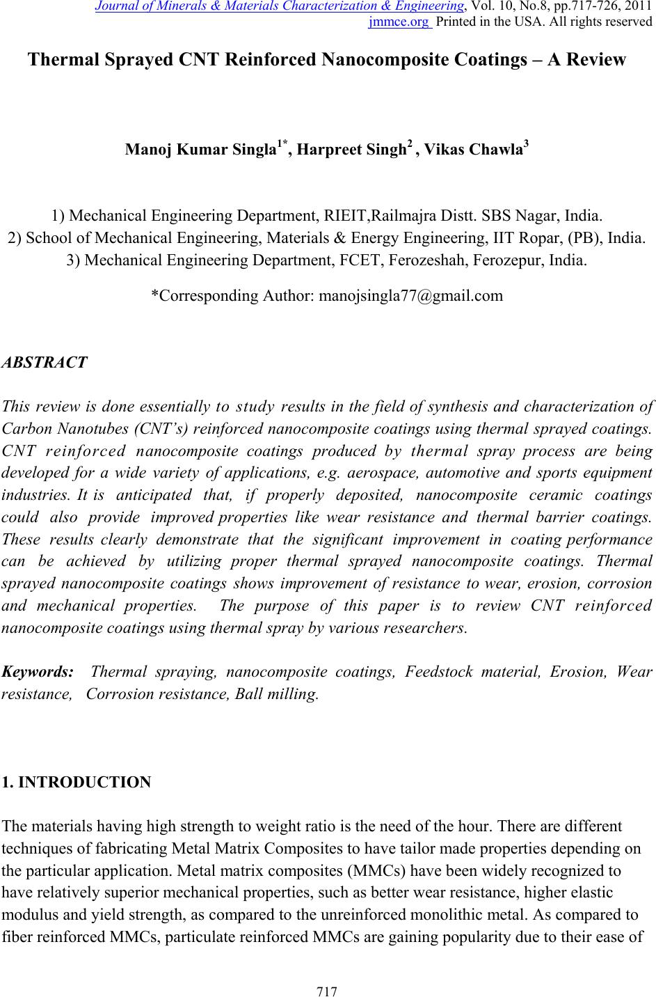 Journal of Minerals & Materials Characterization & Engineering, Vol. 10, No.8, pp.717-726, 2011 jmmce.org Printed in the USA. All rights reserved 717 Thermal Sprayed CNT Reinforced Nanocomposite Coatings – A Review Manoj Kumar Singla1*, Harpre et Si ng h2 , Vikas Chawla3 1) Mechanical Engineering Department, RIEIT,Railmajra Distt. SBS Nagar, India. 2) School of Mechanical Engineering, Materials & Energy Engineering, IIT Ropar, (PB), India. 3) Mechanical Engineering Department, FCET, Ferozeshah, Ferozepur, India. *Corresponding Author: manojsingla77@gmail.com ABSTRACT This review is done essentially t o s tu dy results in the field of synthesis and characterization of Carbon Nanotubes (CNT’s) reinforced nanocomposite coatings using thermal sprayed coatings. CNT reinforced nanocomposite coatings produced by thermal spray process are being developed for a wide variety of applications, e.g. aerospace, automotive and sports equipment industries. It is anticipated that, if properly deposited, nanocomposite ceramic coatings could also provide improved properties like wear resistance and thermal barrier coatings. These results clearly demonstrate that the significant improvement in coating performance can be achieved by utilizing proper thermal sprayed nanocomposite coatings. Thermal sprayed nanocomposite coatings shows improvement of resistance to wear, erosion, corrosion and mechanical properties. The purpose of this paper is to review CNT reinforced nanocomposite coa t i ngs usi ng thermal spray by various researchers . Keywords: Thermal spraying, nanocomposite coatings, Feedstock material, Erosio n, Wear resistance, Corrosi o n resistan c e , Ball milling. 1. INTRODUCTION The materials having high strength to weight ratio is the need of the hour. There are different techniques of fabricating Metal Matrix Composites to have tailor made properties depending on the particular application. Metal matrix composites (MMCs) have been widely recognized to have relatively superior mechanical properties, such as better wear resistance, higher elastic modulus and yield strength, as compared to the unreinforced monolithic metal. As compared to fiber reinforced MMCs, particulate reinforced MMCs are gaining popularity due to their ease of 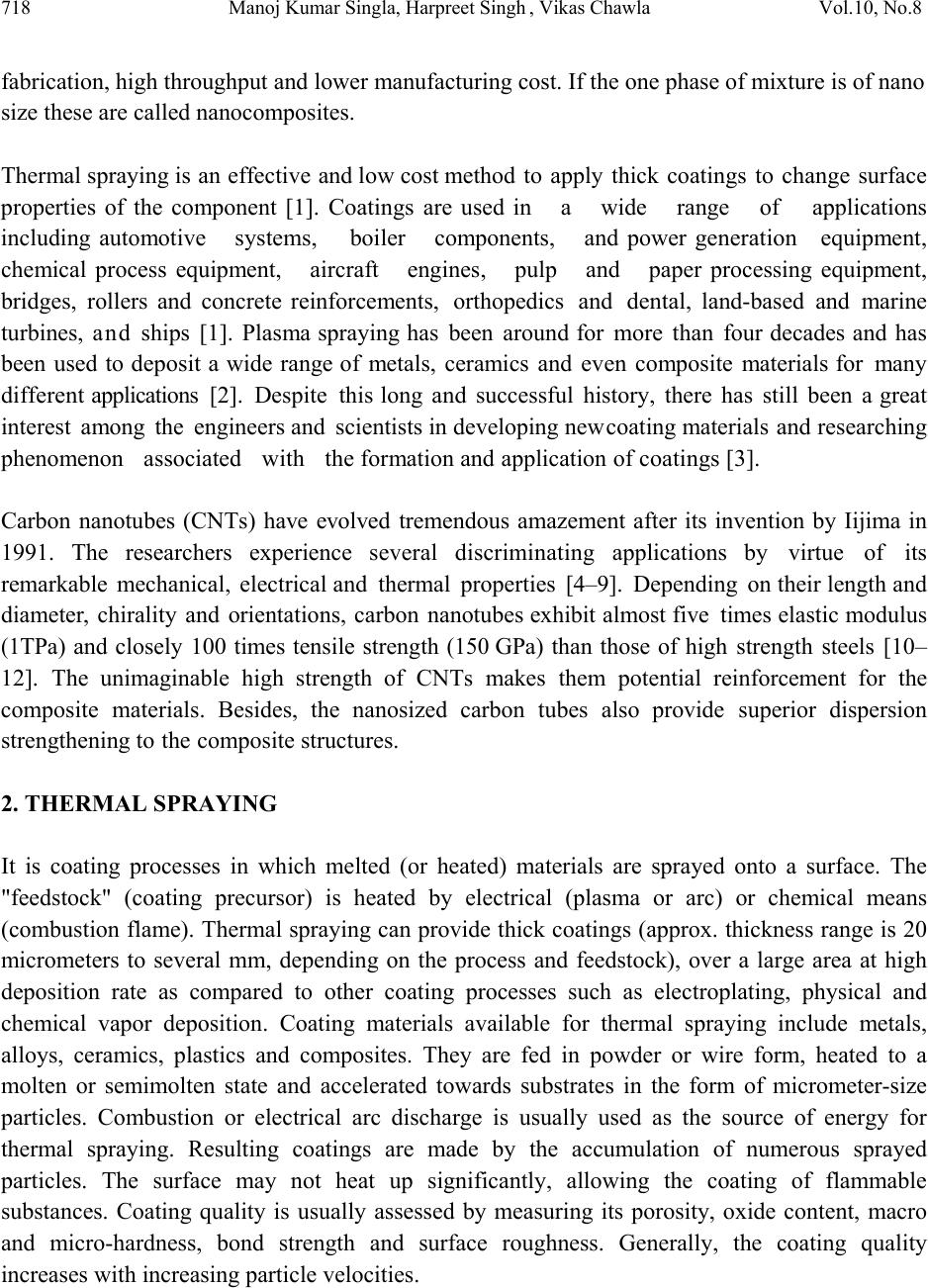 718 Manoj Kumar Singla, Harpreet Singh , Vikas Chawla Vol.10, No.8 fabrication, high throughput and lower manufacturing cost. If the one phase of mixture is of nano size these are called nanocomposites. Thermal spraying is an effective and low cost method to apply thick coatings to change surface properties of the component [1]. Coatings are used in a wide range of applications including automotive systems, boiler components, and power generation equipment, chemical process equipment, aircraft engines, pulp and paper processing equipment, bridges, rollers and concrete reinforcements, orthopedics and dental, land-based and marine turbines, and ships [1]. Plasma spraying has been around for more than four decades and has been used to deposit a wide range of metals, ceramics and even composite materials for many different applications [2]. Despite this long and successful history, there has still been a great interest among the engineers and scientists in developing new coating materials and researching phenomenon associated with the formation and application of coatings [3]. Carbon nanotubes (CNTs) have evolved tremendous amazement after its invention by Iijima in 1991. The researchers experience several discriminating applications by virtue of its remarkable mechanical, electrical and thermal properties [4–9]. Depending on their length and diameter, chirality and orientations, carbon nanotubes exhibit almost five times elastic modulus (1 TPa) and closely 100 times tensile strength (150 GPa) than those of high strength steels [10– 12]. The unimaginable high strength of CNTs makes them potential reinforcement for the composite materials. Besides, the nanosized carbon tubes also provide superior dispersion strengthening to the composite structures. 2. THERMAL SPRAYING It is coating processes in which melted (or heated) materials are sprayed onto a surface. The "feedstock" (coating precursor) is heated by electrical (plasma or arc) or chemical means (combustion flame). Thermal spraying can provide thick coatings (approx. thickness range is 20 micrometers to several mm, depending on the process and feedstock), over a large area at high deposition rate as compared to other coating processes such as electroplating, physical and chemical vapor deposition. Coating materials available for thermal spraying include metals, alloys, ceramics, plastics and composites. They are fed in powder or wire form, heated to a molten or semimolten state and accelerated towards substrates in the form of micrometer-size particles. Combustion or electrical arc discharge is usually used as the source of energy for thermal spraying. Resulting coatings are made by the accumulation of numerous sprayed particles. The surface may not heat up significantly, allowing the coating of flammable substances. Coating quality is usually assessed by measuring its porosity, oxide content, macro and micro-hardness, bond strength and surface roughness. Generally, the coating quality increases with increasing particle velocities. 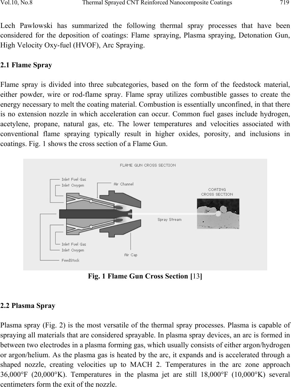 Vol.10, No.8 Thermal Sprayed CNT Reinforced Nanocomposite Coatings 719 Lech Pawlowski has summarized the following thermal spray processes that have been considered for the deposition of coatings: Flame spraying, Plasma spraying, Detonation Gun, High Velocity Oxy-fuel (HVOF), Arc Spraying. 2.1 Flame Spray Flame spray is divided into three subcategories, based on the form of the feedstock material, either powder, wire or rod-flame spray. Flame spray utilizes combustible gasses to create the energy necessary to melt the coating material. Combustion is essentially unconfined, in that there is no extension nozzle in which acceleration can occur. Common fuel gases include hydrogen, acetylene, propane, natural gas, etc. The lower temperatures and velocities associated with conventional flame spraying typically result in higher oxides, porosity, and inclusions in coatings. Fig. 1 shows the cross section of a Flame Gun. Fig. 1 Flame Gun Cross Section [13] 2.2 Plasma Spray Plasma spray (Fig. 2) is the most versatile of the thermal spray processes. Plasma is capable of spraying all materials that are considered sprayable. In plasma spray devices, an arc is formed in between two electrodes in a plasma forming gas, which usually consists of either argon/hydrogen or argon/helium. As the plasma gas is heated by the arc, it expands and is accelerated through a shaped nozzle, creating velocities up to MACH 2. Temperatures in the arc zone approach 36,000°F (20,000°K). Temperatures in the plasma jet are still 18,000°F (10,000°K) several centimeters form the exit of the nozzle.  720 Manoj Kumar Singla, Harpreet Singh , Vikas Chawla Vol.10, No.8 Fig. 2 Plasma Gun Cross Section [14] 2.3 Detonation Gun Spray The D-gun™, shown schematically in Figure 3, includes a long, water cooled barrel with an ID of about 25mm (Schwarz, 1980). A mixture of oxygen (4) and acetylene (5) is fed into the barrel, together with a charge of powder (1). The gas is ignited, explodes and its detonation wave accelerates the powder. In order to avoid ‘backfiring’, i.e. explosion of the fuel gas supply, an inert gas, such as nitrogen, is used between the portions of exploding mixture. Fig. 3 Schematic of D-gun process: 1. powder injection 2. Spark plug 3. Gun barrel 4. Oxygen input 5. Nitrogen input [15] Nitrogen also purges the barrel. The detonation process therefore has the following cycles (Kadyrov and Kadyrov, 1995): • Injection of oxygen and fuel into the combustion chamber; • Injection of powder and nitrogen to prevent ‘backfiring’;  Vol.10, No.8 Thermal Sprayed CNT Reinforced Nanocomposite Coatings 721 • Ignition of mixture and acceleration of powder; • Purging of barrel by nitrogen. There are 1–15 detonations per second with purges of nitrogen between them. 2.4 High Velocity Oxy-fuel (HVOF) Spray High-velocity, oxy-fuel, (HVOF) Fig. 4 devices are a subset of flame spray. There are two distinct differences between conventional flame spray and HVOF. HVOF utilizes confined combustion and an extended nozzle to heat and accelerate the powdered coating material. Typical HVOF devices operate at hypersonic gas velocities, i.e. greater than MACH 5. The extreme velocities provide kinetic energy which help produce coatings that are very dense and very well adhered in the as-sprayed condition. Fig. 4 HVOF Gun Cross Section [16] 2.5 Arc Spray Like flame spray, electric-arc spray (Fig. 5) was invented in the early 20th century. Even though the technology has been around for a long time, it still remains a very powerful thermal spray technology. Electric-arc spray uses a simple, low power arc drawn between two electrically charged wires. Arc spray equipment resembles GMAW (MIG) welding equipment, in the power source and wire feeding units. Common arc spray units are capable of spraying iron and copper alloys at rates up to 40 lbs./hr (18 Kg/hr.) using only 12 kW (42 MJ) of electricity. Electric-arc spraying produces the fastest coating rates of any technology. Electric-arc spray devices are thermally efficient and, because there is no flame or plasma, little heat are transferred to the part being coated. 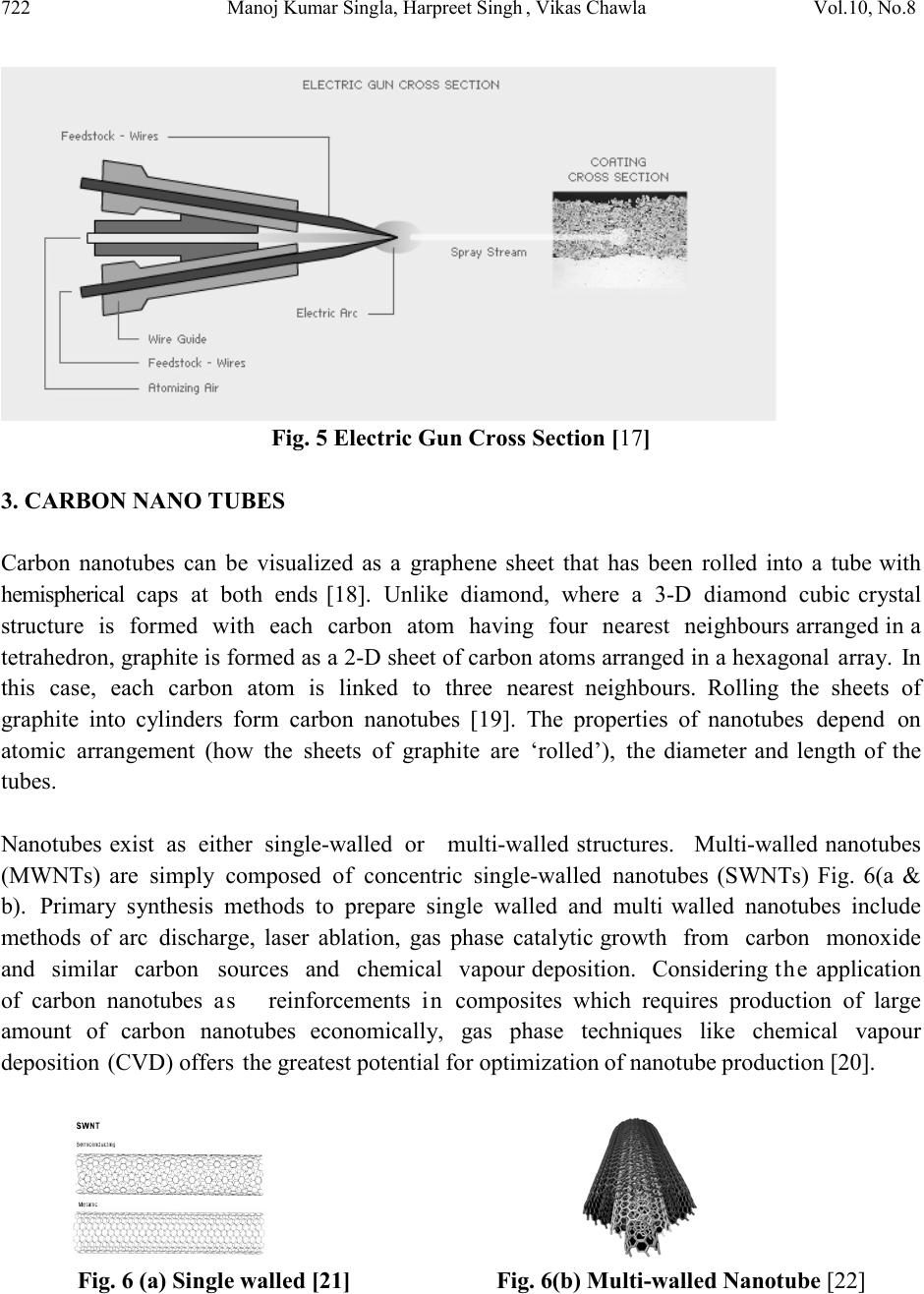 722 Manoj Kumar Singla, Harpreet Singh , Vikas Chawla Vol.10, No.8 Fig. 5 Electric Gun Cross Section [17] 3. CARBON NANO TUBES Carbon nanotubes can be visualized as a graphene sheet that has been rolled into a tube with hemispherical caps at both ends [18]. Unlike diamond, where a 3-D diamond cubic crystal structure is formed with each carbon atom having four nearest neighbours arranged in a tetrahedron, graphite is formed as a 2-D sheet of carbon atoms arranged in a hexagonal array. In this case, each carbon atom is linked to three nearest neighbours. Rolling the sheets of graphite into cylinders form carbon nanotubes [19]. The properties of nanotubes depend on atomic arrangement (how the sheets of graphite are ‘rolled’), the diameter and length of the tubes. Nanotubes exist as either single-walled or multi-walled structures. Multi-walled nanotubes (MWNTs) are simply composed of concentric single-walled nanotubes (SWNTs) Fig. 6(a & b). Primary synthesis methods to prepare single walled and multi walled nanotubes include methods of arc discharge, laser ablation, gas phase catalytic growth from carbon monoxide and similar carbon sources and chemical vapour deposition. Considering the application of carbon nanotubes as reinforcements in composites which requires production of large amount of carbon nanotubes economically, gas phase techniques like chemical vapour deposition (CVD) offers the greatest potential for optimization of nanotube production [20]. Fig. 6 (a) Single walled [21] Fig. 6(b) Multi-walled Nanotube [22]  Vol.10, No.8 Thermal Sprayed CNT Reinforced Nanocomposite Coatings 723 The purpose of this paper is to review the CNT reinforced nanocomposite coatings using thermal spraying techniques by various researchers. 4. STUDIES RELATED TO THERMAL SPRAY COATINGS T. Laha et al. [23] synthesized and characterized carbon nanotubes as reinforced composites of unique properties. In his endeavor, free standing structures of Al-based nanostructured composite with carbon nanotubes as second phase particles has been synthesized by plasma spray forming technique. Optical microscopy, scanning electron microscopy, X-ray diffraction, transmission electron microscopy has been carried out to analyze the composite structure and to verify the retention of carbon nanotubes. Besides, density and microhardness measurements have been performed to understand the effect of carbon nanotube reinforcement on the mechanical properties of the composite. It has been observed that microhardness increased from 85 to 146 The characterization affirms the presence of unmelted and chemically unreacted carbon nanotubes in the composite. Moreover, the composite experienced an increase in relative microhardness due to the presence of Carbon Nano tubes. T. Laha et al.[24] fabricated free standing structures of hypereutectic aluminum-23 wt% silicon nanocomposite with multiwalled carbon nanotubes (MWCNT) reinforcement by two different thermal spraying technique viz Plasma Spray Forming (PSF) and High Velocity Oxy-Fuel (HVOF) Spray Forming. Comparative microstructural and mechanical property evaluation of the two thermally spray formed nanocomposites has been carried out. Presence of nanosized grains in the Al–Si alloy matrix and physically intact and undamaged carbon nanotubes were observed in both the nanocomposites. Excellent interfacial bonding between Al alloy matrix and MWCNT was observed. The elastic modulus (82.8+9.3 GPa) and hardness (1.93+0.14 GPa) of HVOF sprayed nanocomposite is found to be higher than PSF sprayed composites. K. Balani et al. [25] evaluated wear behavior of plasma-sprayed carbon nanotube (CNT)- reinforced hydroxyapatite (HA) coating in the simulated body fluid environment. Apart from enhancing the fracture toughness and providing biocompatibility, CNT-reinforced HA coating demonstrated superior wear resistance compared with that of hydroxyapatite coating without CNT. Initiation and propagation of micro- cracks during abrasive wear of plasma-sprayed hydroxyapatite coatings was suppressed by CNT reinforcement. Surface characterization and wear studies have shown that in addition to acting as underprop lubricant; CNTs provide reinforcement via stretching and splat- bridging for enhanced abrasion resistance in vitro. K. Balani et al. [26] dispersed CNTs are grown on Al2O3 powder particles in situ by the catalytic chemical vapor deposition (CCVD) technique. Consequently, 0.5 wt.% CNT-reinforced Al2O3 particles were successfully plasma sprayed to obtain a 400 µm thick coating on the steel substrate. In situ CNTs grown on Al2O3 shows a promising enhancement in hardness and fracture toughness of the plasma-sprayed coating attributed to the existence of strong 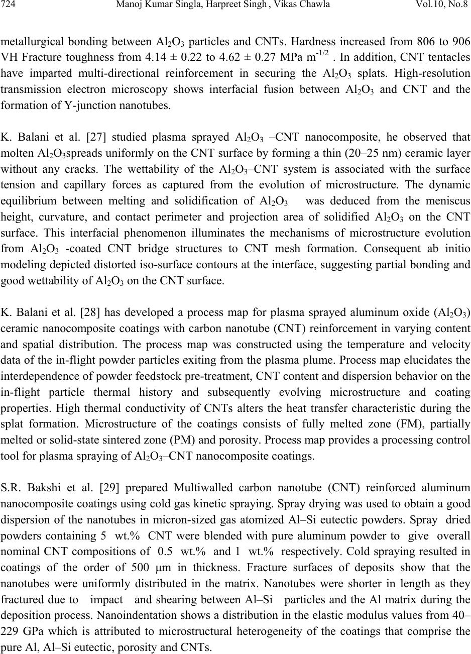 724 Manoj Kumar Singla, Harpreet Singh , Vikas Chawla Vol.10, No.8 metallurgical bonding between Al2O3 particles and CNTs. Hardness increased from 806 to 906 VH Fracture toughness from 4.14 ± 0.22 to 4.62 ± 0.27 MPa m-1/2 . In addition, CNT tentacles have imparted multi-directional reinforcement in securing the Al2O3 splats. High-resolution transmission electron microscopy shows interfacial fusion between Al2O3 and CNT and the formation of Y-junction nanotubes. K. Balani et al. [27] studied plasma sprayed Al2O3 –CNT nanocomposite, he observed that molten Al2O3spreads uniformly on the CNT surface by forming a thin (20–25 nm) ceramic layer without any cracks. The wettability of the Al2O3–CNT system is associated with the surface tension and capillary forces as captured from the evolution of microstructure. The dynamic equilibrium between melting and solidification of Al2O3 was deduced from the meniscus height, curvature, and contact perimeter and projection area of solidified Al2O3 on the CNT surface. This interfacial phenomenon illuminates the mechanisms of microstructure evolution from Al2O3 -coated CNT bridge structures to CNT mesh formation. Consequent ab initio modeling depicted distorted iso-surface contours at the interface, suggesting partial bonding and good wettability of Al2O3 on the CNT surface. K. Balani et al. [28] has developed a process map for plasma sprayed aluminum oxide (Al2O3) ceramic nanocomposite coatings with carbon nanotube (CNT) reinforcement in varying content and spatial distribution. The process map was constructed using the temperature and velocity data of the in-flight powder particles exiting from the plasma plume. Process map elucidates the interdependence of powder feedstock pre-treatment, CNT content and dispersion behavior on the in-flight particle thermal history and subsequently evolving microstructure and coating properties. High thermal conductivity of CNTs alters the heat transfer characteristic during the splat formation. Microstructure of the coatings consists of fully melted zone (FM), partially melted or solid-state sintered zone (PM) and porosity. Process map provides a processing control tool for plasma spraying of Al2O3–CNT nanocomposite coatings. S.R. Bakshi et al. [29] prepared Multiwalled carbon nanotube (CNT) reinforced aluminum nanocomposite coatings using cold gas kinetic spraying. Spray drying was used to obtain a good dispersion of the nanotubes in micron-sized gas atomized Al–Si eutectic powders. Spray dried powders containing 5 wt.% CNT were blended with pure aluminum powder to give overall nominal CNT compositions of 0.5 wt.% and 1 wt.% respectively. Cold spraying resulted in coatings of the order of 500 μm in thickness. Fracture surfaces of deposits show that the nanotubes were uniformly distributed in the matrix. Nanotubes were shorter in length as they fractured due to impact and shearing between Al–Si particles and the Al matrix during the deposition process. Nanoindentation shows a distribution in the elastic modulus values from 40– 229 GPa which is attributed to microstructural heterogeneity of the coatings that comprise the pure Al, Al–Si eutectic, porosity and CNTs. 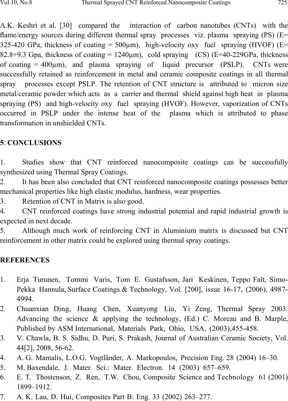 Vol.10, No.8 Thermal Sprayed CNT Reinforced Nanocomposite Coatings 725 A.K. Keshri et al. [30] compared the interaction of carbon nanotubes (CNTs) with the flame/energy sources during different thermal spray processes viz. plasma spraying (PS) (E= 325-420 GPa, thickness of coating = 500µm), high-velocity oxy fuel spraying (HVOF) (E= 82.8+9.3 Gpa, thickness of coating = 1240µm), cold spraying (CS) (E=40-229GPa, thickness of coating = 400µm), and plasma spraying of liquid precursor (PSLP). CNTs were successfully retained as reinforcement in metal and ceramic composite coatings in all thermal spray processes except PSLP. The retention of CNT structure is attributed to micron size metal/ceramic powder which acts as a carrier and thermal shield against high heat in plasma spraying (PS) and high-velocity oxy fuel spraying (HVOF). However, vaporization of CNTs occurred in PSLP under the intense heat of the plasma which is attributed to phase transformation in unshielded CNTs. 5. CONCLUSIONS 1. Studies show that CNT reinforced nanocomposite coatings can be successfully synthesized using Thermal Spray Coatings. 2. It has been also concluded that CNT reinforced nanocomposite coatings possesses better mechanical properties like high elastic modulus, hardness, wear properties. 3. Retention of CNT in Matrix is also good. 4. CNT reinforced coatings have strong industrial potential and rapid industrial growth is expected in next decade. 5. Although much work of reinforcing CNT in Aluminium matrix is discussed but CNT reinforcement in other matrix could be explored using thermal spray coatings. REFERENCES 1. Erja Turunen, Tom mi Varis, Tom E. Gustafsson, Jari Keskinen, Teppo Falt, Simo- Pekka Hannula, Surface Coatings & Technology, Vol. [200], issue 16-17, (2006), 4987- 4994. 2. Chuanxian Ding, Huang Chen, Xuanyong Liu, Yi Zeng, Thermal Spray 2003: Advancing the science & applying the technology, (Ed.) C. Moreau and B. Marple, Published by ASM International, Materials Park, Ohio, USA, (2003),455-458. 3. V. Chawla, B. S. Sidhu, D. Puri, S. Prakash, Journal of Australian Ceramic Society, Vol. 44[2], 2008, 56-62. 4. A. G. Mamalis, L.O.G. Vogtländer, A. Markopoulos, Precision Eng. 28 (2004) 16–30. 5. M. Baxendale, J. Mater. Sci.: Mater. Electron. 14 (2003) 657–659. 6. E. T. Thostenson, Z. Ren, T.W. Chou, Composite Science and Technology 61 (2001) 1899–1912. 7. A. K. Lau, D. Hui, Composites Part B: Eng. 33 (2002) 263–277.  726 Manoj Kumar Singla, Harpreet Singh , Vikas Chawla Vol.10, No.8 8. Ph. Mauron, Ch. Emmenegger, A. Züttel, Ch. Nützenadel, P. Sudan, L. Schlapbach, Carbon 40 (2002) 1339–1344. 9. X. F. Zhang, X.B. Zhang, G.V. Tendeloo, S. Amelinckx, M. Beeck, J.V. Landuyt, Journal of Crystal Growth 130 (1993) 368–382. 10. R. B. Pipes, P. Hubert, Composite Science and Technology 62 (2002) 419–428. 11. J. Salvetat-Delmotte, A. Rubio, Carbon 40 (2002) 1729–1734. 12. E. Saether, S.J. Frankland, R.B. Pipes, Composite Science and Technology 63 (2003) 1543–1550. 13. URL: http://www.tstcoatings.com/flame_spray.html 14. URL; http://www.tstcoatings.com/plasma_spray.html 15. Lech Pawlowski, The Science and Engineering of Thermal Spray Coatings, John Wiley & Sons Ltd.. 16. URL; http://www.tstcoatings.com/HVOF.html 17. URL; http://www.tstcoatings.com/electric_arc_spray.html 18. S. Iijima, , Nature, vol. 354, (1991) 56-58. 19. P. J. F. H a rr i s, ‘Carbon nanotubes and related structures’, Cambridge University press, 1999. 20. S. S. Samal, S. Bal, JMMCE, vol. 7 No. 4 (2008) 355-370. 21. URL: http://www.selahtechnologies.com/technology.aspx 22. URL: http://www.robaid.com/tech/nanotechnologies-carbon-nanotubes.htm 23. T. Laha, A. Agarwal, Tim Mc Kechnie, S. Seal, Material Science and Engineering (2004) 249-258. 24. T. Laha, Y. Liu, A. Agarwal, Journal of Nano Science and Nanotechnology, Vol. 7, (2007)1-10. 25. K. Balani, Yao Chen, Sandip P. Harimkar, Narendra B. Dahotre, A. Agarwal, Acta Biomaterialia 3 (2007) 944-951. 26. K. Balani, T. Zhang, A. Karakoti, W. Z. Li, S. Seal, A.Agarwal, Acta Materialia (2007). 27. K. Balani, A. Agarwal, Nanotechnology19 (2008) 1-8, IOP Publishing Ltd. 28. K. Balani, A. Agarwal, Surface & Coating Technology 202 (2008) 4270-4277. 29. S. R. Bakshi, V. Singh, K. Balani, D. Graham McCartney, S. Seal, A. Agarwal, Surface & Coating Technology 202 (2008) 5162-5169. 30. A. K. Keshri, K. Balani, S. R. Bakshi, V. Singh, T. Laha, S. Seal, A. Agarwal, Surface & Coating Technology 203 (2009) 2193-2201. |