Paper Menu >>
Journal Menu >>
 Journal of Minerals & Materials Characterization & Engineering, Vol. 10, No.8, pp.693-705, 2011 jmmce.org Printed in the USA. All rights reserved 693 Development of Iron Based Brake Friction MMC Used for Military Aircraft Application by A New P/M Route Mohammad Asif*, K. Chandra and P.S. Misra Metallurgical and Materials Engineering Department, Indian Institute of Technology, Roorkee. Roorkee- 247667, India * Corresponding Author: masifiitr@gmail.com, asif5_mohd@yahoo.com ABSTRACT A new P/M route based hot powder pre-form forging process has been evolved to develop high density brake materials for heavy duty applications. Number of iron based MMC’s so developed offer better characteristics for braking applications in comparison to the materials developed through conventional P/M route based on high pressure compaction and pressure sintering. The process so developed in the present investigations is much simpler and easy to adopt by existing P/M industries. Hot powder pre-form forging technique for making heavy duty brake pads offers better opportunity for pore free material with better bonding between various metallic and non-metallic constituents. After conducting an initial characterization such as hardness, density and Pin-on Disc tests, the samples were tested for high energy (32,933kgfm) on Sub-scale dynamometer under Rejected Take Off conditions. The results have also been compared with respect to brake pads employed in heavy duty Military aircraft tested under identical laboratory conditions. The present work indicates that the newly developed materials compare better than the one being currently employed in heavy duty aircraft. The reasons for better performance are improved processing technique a nd resulting higher levels of density and improved binding of the product. Keywords: brake pad; heavy duty Aircraft brakes; Powder Metallurgy. 1. INTRODUCTION Friction materials are used in clutch and brake devices of many automobiles, railways, civilian/military aircrafts, earth movers, presses, and various types of load lifting devices etc. To control the speed, resin bonded friction materials are used in commercial cars and light duty automobiles. However, resin bonded materials do not suit in heavy duty brakes because of 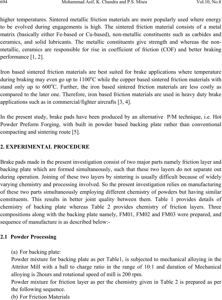 694 Mohammad Asif, K. Chandra and P.S. Misra Vol.10, No.8 higher temperatures. Sintered metallic friction materials are more popularly used where energy to be evolved during engagements is high. The sintered friction material consists of a metal matrix (basically either Fe-based or Cu-based), non-metallic constituents such as carbides and ceramics, and solid lubricants. The metallic constituents give strength and whereas the non- metallic, ceramics are responsible for rise in coefficient of friction (COF) and better braking performance [1, 2]. Iron based sintered friction materials are best suited for brake applications where temperature during braking may even go up to 1100oC while the copper based sintered friction materials with stand only up to 600oC. Further, the iron based sintered friction materials are less costly as compared to the later one. Therefore, iron based friction materials are used in heavy duty brake applications such as in commercial/fighter aircrafts [3, 4]. In the present study, brake pads have been produced by an alternative P/M technique, i.e. Hot Powder Preform Forging, with built in powder based backing plate rather than conventional compacting and sintering route [5]. 2. EXPERIMENTAL PROCEDURE Brake pads made in the present investigation consist of two major parts namely friction layer and backing plate which are formed simultaneously, such that these two layers do not separate out during operation. Joining of these two layers by sintering is usually difficult because of widely varying chemistry and processing involved. So the present investigation relies on manufacturing of these two parts simultaneously employing different chemistry of powders but having similar constituents. This results in better joint quality between them. Table 1 provides details of chemistry of backing plate whereas Table 2 provides chemistry of friction layers. Three compositions along with the backing plate namely, FM01, FM02 and FM03 were prepared, and sequence of manufacture is as described below:- 2.1 Powder Processing (a) For backing plate: Powder mixture for backing plate as per Table1, is subjected to mechanical alloying in the Attritor Mill with a ball to charge ratio in the range of 10:1 and duration of Mechanical alloying is 2hours and rotational speed of mill is 200 rpm. Powder mixture for friction layer as per the chemistry given in Table 2 is prepared as per the following sequence. (b) For Friction Materials  Vol.10, No.8 Development of Iron Based Brake Friction MMC 695 - SIC powder is mechanically alloyed with sulphide/sulphate powders and of graphite powder (having size range 0-120micron) as shown in Table 3.The parameters of mechanically alloying are:- - Attritor speed (200rpm), Ball to charge ratio (10:1), Duration (60mins.). This will ensure coating of soft powders on hard SIC powder. - Entire amount of iron and other powders as per the chosen chemistry is mechanically alloyed with graphite powder in Attritor Mill as mentioned above. - The two powder mixtures so prepared are then mechanically mixed with each other 2.2 Powder Compacting Powder compaction takes place in a suitably designed die in accordance with the given shape of disc brake pad for example, suitable for MIG27 aircraft. Requisite quantity of backing plate powder mixture is first filled to a uniform height. Thereafter, friction layer powder mixture in requisite quantity is filled in the die. The filling of these layers of powder is done on fixed weight basis as per the design say Fig.1 (a), and densities of respective layers. Both the layers of powder mixture are simultaneously pressed in a Screw forging press with the help of upper and lower punches at a pressure in the range of 150 to 450MPa. The compact so pressed is ejected out of the die. The die is suitably lubricated employing graphite /Zinc stearate in the suspension of methyl alcohol/ethyl alcohol/acetone prior to filling for easy ejection without cracking of green compact. 2.3 Preform Coating The green compact so produced is coated with an indigenously developed ceramic coating to protect it from oxidation when subjected to heating. The coating is baked to remove moisture from it at a temp of 120 oC for 2 hrs in an oven [6]. 2.4 Heating The coated green compacts are heated in a furnace. The operating temperature of the furnace ranges from 1050oC for iron based brake pads, holding time 1 hr. 2.5 Hot powder Preform Forging The hot powder preform are taken out from the furnace and quickly transferred into the hot die duly lubricated with graphite and fitted in the forging press. The forging is done at a speed of 500mm/s. The preform fully consolidates to its near theoretical density on forging. The forged component is later on ejected out of the die.  696 Mohammad Asif, K. Chandra and P.S. Misra Vol.10, No.8 2.6 Annealing The forged pads are subjected to high temperature resistant ceramic glassy coating again and, then annealed at a temperature of 710oC for 5 hours to adjust hardness of friction layer to < 100 BHN. On cooling the coating peels off by itself and residual coating if any is removed by minor surface finishing operations. As shown in Fig.1(b) Frictiom Ma terial Backing Plate 14 3 28 14 R172 R116 Ø10 Ø5 56 20° A A R2.5 R5 Front ViewSection View A -A 7 to 1 0 Figure 1(a). Design of Brake Pad as developed in the present investigation  Vol.10, No.8 Development of Iron Based Brake Friction MMC 697 Annealin g at710OCu p to2hrs Pre p arationofthesam p lesforvarioustests 1. DensityandHardnessmeasurement 2. Pin‐on‐discweartest 3. Temperaturerisemeasurement 4. FractureTest 5. SubscaleInertiaDynamometertest 6. Materialcharacterization(Metallographic,SEMwith EDAX,X‐rayMappingetc.) Metallicpowders(Fe,Cu,and Ferroalloysetc) Non‐metallic,Ceramics, (SiC) Sievingofpowdersfromsteelballs Blending/MixingofPowdermixture Raw materials Lubricants(Graphite, Sb2S3,BaSO4etc) MakinggreencompactusingScrewTypeForgingpress ApplyHightemperatureresistantglassycoatingonsamples Dryingsamplesinopenatmosphere Heatingthesamplesinmufflefurnaceupto1050oCfor1hr Fillingofpowderinoptimizedquantityinacloseddie HotFor g in g thesam p lesincloseddie  698 Mohammad Asif, K. Chandra and P.S. Misra Vol.10, No.8 Fig. 1(b). Process Flow sheet for manufacturing of iron based Brake pads with built-in powder based backing plate Table 1. Chemistry of back plate materials. Table 2. Chemistry of friction materials. Symbol Chemistry (wt%) Metallic Constituents Ceramic Constituents Lubricants FM01 Fe-70.5, Cu-11 SiC-6 Graphite-6.5, BaSO4-6 FM02 Fe-70.1, Cu-11, Sn-1 P-0.4, SiC-6 Graphite-6.5,Sb2S3-5 FM03 Fe-70, Cu-11, Sn-2 P-0.5,SiC-4 Graphite-6.5, BaSO4-6 Table 3. Sizes of powders employed. S.No. Powder Size range Source 1 Iron powder -120µm Hoganas Industries Ltd. 2 Copper powder -120µm Electrolytic 3 Graphite -200 to +150µm Natural Crystalline Grade 4 Ferro-phosphorus -45µm Commercial grade 5 Tin powder -75µm Atomized 6 Silicon Carbide -180 to +150µm Chemical grade 7 Barium Sulphate/ Antimony Trisulpide -45µm Chemical grade Sample Name C % Cu % P % SiC % Fe % FM01-FM03 0.5 2.5 - 1 Balance  Vol.10, No.8 Development of Iron Based Brake Friction MMC 699 3. RESULTS AND DISCUSSIONS: 3.1 Characterization of Friction Materials/Pads The brake pads so produced along with the built-in powder based backing plates are characterized for physical, and functional properties namely density, hardness etc. Also pin-on- disc wear test, sub-scale brake inertia dynamometer tests are carried out. 3.1.1 Determination of density and hardness The basic method of determining the density of our samples is by measuring the ratio of mass and volume of the samples was used. Density depends upon extent of forging and annealing treatments thereafter. It also indirectly depends upon chemistry of friction materials. In this paper, the density of our sample was estimated by Archimedes principle as shown in Table 4. [7] The Brinell hardness test method consists of indenting the test material with a 10 mm diameter hardened steel ball subjected to a load of 31.25 kg applied for10–15 s. The diameter of the indentation left in the test material is measured with a low powered microscope. The diameter of the impression is the average of two readings at right angles and the use of a Brinell hardness number table can simplify the determination of the Brinell hardness. Brinell hardness number of test pins is shown in Table 4. The sample FM03 has high hardness, this due to the improper annealing treatment and presence of hard materials like SiC. Hence it may not give desired results Table 4. Density and hardness iron based brake friction elements. Samples FM01 FM02 FM03 Density Ρ (gm/ cm2) 6.3 6.1 6.0 Hardness (BHN) 110 118 130 3.1.2 Pin on disc test The results of wear test are summarized in Table 5. It shows that the samples FM01, FM02, have the higher wear resistance. Sample FM03 has higher coefficient of friction (COF) shown in Table5, which is suitable for heavy duty applications. The rise in temperature is also marginally low except the sample FM02. The noise level for the sample FM01 is less as compared to for the samples FM02, FM03 shown in Table 5.  700 Mohammad Asif, K. Chandra and P.S. Misra Vol.10, No.8 Table 5. Pin-on-disc wear test results. (contact area of pin: 7×7 mm2 , sliding speed of 9m/s and applied load of 8 kg). Samples Wear loss, in gm Coefficient of Friction, (COF) Max Temperature Rise Noise level, dB Max Min Avg oC Max Min Avg. FM01 0.35 0.24 0.18 0.21 207 30 24 27 FM02 0.55 0.25 0.21 0.23 225 39 31 35 FM03 0.81 0.28 0.26 0.27 147 37 29 33 3.1.3 Sub scale dynamometer test The test input parameters for the various aircrafts applications are shown in Table 6. The required test output parameter values are shown in Table 7. The test results are shown in Fig.2 and Fig.3 for MIG 27 rotor application; the run down time are nearly in the specified ranges as that of output parameters (Table 7). However wear (in grams) is slightly higher in pads FM01 and FM03 when the wear is expressed in terms of thickness all the pads are within the specified ranges as shown in Table 7. These pads seem to be suitable for MIG27 aircraft rotor applications. The test results for MIG 27 rotor application are best suitable in terms of run down time; wear in thickness, coefficient of friction. Figure 2.and Fig.3 Show the test performance of three compositions starting from FM01 to FM03 for heavy duty applications (high energy under reduced conditions). The shaded regions in these figures indicate maximum and minimum ranges of permissible test parameters as described in the above Table 7. Experimental points in these figures have not been shown for the sake of clarity and the curve smoothening has been done. This has been done just to get a clearer picture of the performance. Shaded regions in these graphs wherever, shown, are corresponding to Table7. Which decides the suitability of application of brake pad developed in the present investigation? There is a general trend in these figures such that a property changes are more severe up to 8 numbers of cycles of the test. Thereafter, the property tends to stabilize. This is because of the initial engagement of stationery brake pads with moving inertia wheel during testing. It can be easily inferred from these figures that with the exception of FM03 (which has performed the worst), all the other combinations tested in the present investigation are suitable for heavy duty aircraft application. However, preference is in the following order: [8] FM02 > FM01 > FM03  Vol.10, No.8 Development of Iron Based Brake Friction MMC 701 It may further be mentioned that the region for poor performance of FM03, is due to higher hardness and lower density combination. It is noteworthy to mention, that MIG 27 Rotor application is very specialized high energy condition for which chemistry of sintered pads is very complex and costly. In comparison to this, chemistry developed in the present investigation is much simpler and offer wide variety of choices to suit this challenging application. Table 6. Test input parameters for mig 27 rotor application. (brake pad contact area: 28.8 cm2) Applications Test Parameters Kinetic energy, kgfm Brake Speed, rpm Brake Force, kgf MIG 27 Rotor 36123 1445 135 Reduced to Actual Pad Area 32933 1445 135 Table 7. Test output parameters for MIG 27 rotor application. Application Test parameter RD Time, sec COF Maximum Wear (for 50 cycles) Min Max Min Max in grams, gm in thickness, mm MIG 27 Rotor - 18 0.20 0.45 10 0.70  702 Mohammad Asif, K. Chandra and P.S. Misra Vol.10, No.8 (a) (b) (c) Fig. 2. Variations of (a) Run down time, (b) Coefficient of friction and (c) Brake torque for test parameters corresponding to MIG-27 aircraft rotor application.  Vol.10, No.8 Development of Iron Based Brake Friction MMC 703 0 0.1 0.2 0.3 0.4 0.5 0.6 0.7 0.8 FM01 FM02 FM03 WearinThi ckness(mm) Samples (a) 0 2 4 6 8 10 12 FM01 FM02 FM03 Wear(gm) Sampl es (b) 82 83 84 85 86 87 88 89 FM01 FM02 FM03 Temp eratu re ( d eg C ) Samples (c) Fig. 3.Variations in wear data (a)in grams,(b) in thickness and (c) Temperature in deg C for 50 numbers of cycles for test parameters corresponding to MIG-27 aircraft rotor application. 3.1.4 Metallographic examinations On the basis of metallographic examination as shown in Fig.4, we have observed that the microstructures of friction layer Fig.4 (a) as well as backing plate are finer and more homogeneous. Backing plate in FM-02 sample which is shown in Fig.4 (c) is a low carbon steel but with very fine ferrite grains, this is because of high speed forging employed during  704 Mohammad Asif, K. Chandra and P.S. Misra Vol.10, No.8 processing providing fast cooled fine grained structure which in turn yields high strength backing plate without resorting to higher carbon steel. The distribution of other constituents in forged samples is also uniform. The microstructure of hot powder preform forged FM-02 sample at the interface as shown in Fig.4(b) indicate strong bonding between backing plate and friction element because of enhanced diffusion of carbon from friction element side to backing plate side and absence of any layered structure at the interface[8]. Figure5., shows the distribution of different elements in sample FM02. It is clear from these pictures that the constituents present in the sample are uniformly distributed. There appears to be no segregation of constituents in the structure. Accordingly, the performance of these samples in actual service conditions is expected to be more consistent in comparison to sintered samples. (a)Friction Layer (FM-02) (b) Interface (FM-02) (c) Backing Layer (FM-02) Fig. 4. Microstructures of Hot Powder Preform Forged Brake pads Interface Surface (FM-02) Iron Silicon Carbide Carbon Copper Phosphorous Fig. 5. X-ray mapping of MIG27 air craft hot powder preforms forged brake pad at Interface layer (backing plate and friction material) at 100x  Vol.10, No.8 Development of Iron Based Brake Friction MMC 705 4. CONCLUSIONS 1. A new set of iron-based friction elements in desired shapes and sizes with built-in powder based backing plate (Net shape) for heavy-duty applications are prepared without using protective H2 gas environment. 2. Use of high temperature oxidation resistant glassy coating which, which can be used for iron/copper, based brake pads and protect it from oxidations at high temperature. 3. Provides much better joint between Friction element and backing plate compare to sintering technology. 4. Yields matching quality of the product compared to sintering technology. 5. Easily adoptable by existing P/M industries without any additional cost. ACKNOWLEDGEMENT We are thankful to HAL Bangalore for providing testing facilities in their works to test our samples on their sub-scale dynamometer. REFERENCES [1] Anderson, A. E., 1992, ASM Handbook, Vol.18, pp569-577, Materials park, OH. [2] Hausner, H., 1970, Vol.4, pp61-72 & pp123-137, Perspectives in Powder Metallurgy, Friction and Anti-friction materials, Plenum press, New York. [3] Nadezda, M. et. al., 2000, Materials Letters Vol.46, pp255–260. [4] So H., 1996, Tribology International Vol.29, pp415-423. [5] S. D. Lenin., Chandra K., Misra P. S., 2009, “New Processing Technology for the Manufacture of Heavy duty Metallo-Ceramic Brake pads” Powder Metallurgy, p6. [6] Misra P. S., Chandra K. “Development of High Temperature Oxidations Resistant Glassy Coating” Indian Patent, application No. 153/DEL/2010 dated Jan. 27, 2010. [7] S. D. Lenin., Development of friction materials through powder metallurgy, 2008. Ph.D. Thesis, Indian Institute of Technology Roorkee (INDIA). [8] Asif M., Chandra K., Misra P. S., 2010 “Characterization of hot powder preform forged Iron Based brake pads for heavy duty applications” paper under review ASME Journal of Tribology, No TRIB-10-1178. [9] Asif M., Chandra K., Misra P. S., 2010, “Microstructure and Mechanical Properties of P/M Processed steel used in brake pads for heavy duty applications by hot powder preform Technique.” Paper accepted and will be published in Material science and Engineering- A, Elsevier journal, for Third International Conference on Recent Advances in Composite Materials, ICRACM-2010 France (December 13-15, 2010). |