Paper Menu >>
Journal Menu >>
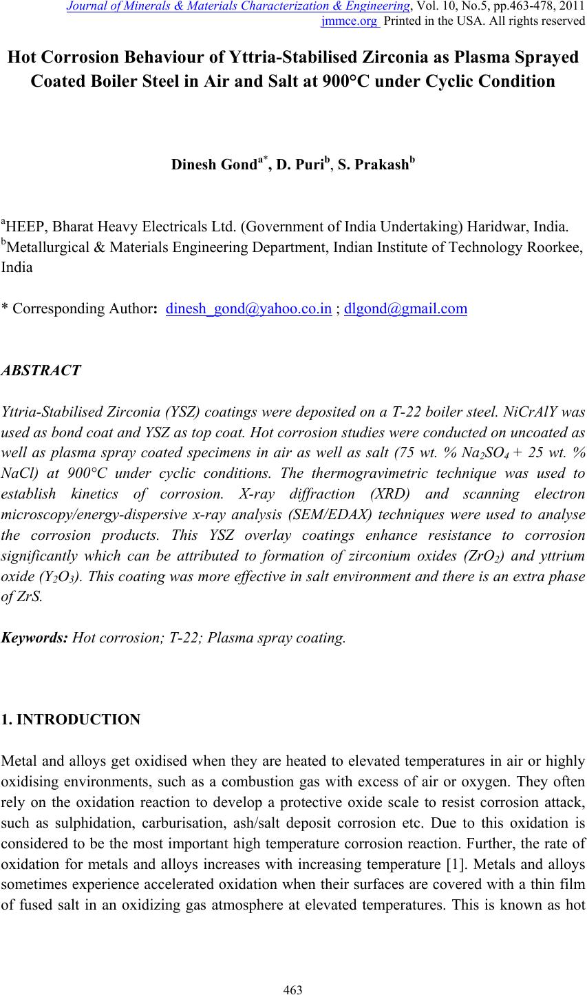 Journal of Mi nerals & Materials Characteriza tion & Engineering, V ol. 10, No.5, pp.463-478, 2011 jmmce.org Printed in the USA. All rights reserved 463 Hot Corrosion Behaviour of Yttria-Stabilised Zirconia as Plasma Sprayed Coated Boiler Steel in Air and Salt at 900°C under Cyclic Condition Dinesh Gonda*, D. Purib, S. Prakashb aHEEP, Bharat Heavy Electricals Ltd. (Government of India Undertaking) Haridwar, India. bMetallurgical & Materials Engineering Department, Indian Institute of Technology Roorkee, India * Corresponding Author: dinesh_gond@yahoo.co.in ; dlgond@gmail.com ABSTRACT Yttria-Stabilised Zirconia (YSZ) coatings were deposited on a T-22 boiler steel. NiCrAlY was used as bond coat and YSZ as top coat. Hot corrosion studies were conducted on uncoated as well as plasma spray coated specimens in air as well as salt (75 wt. % Na2SO4 + 25 wt. % NaCl) at 900°C under cyclic conditions. The thermogravimetric technique was used to establish kinetics of corrosion. X-ray diffraction (XRD) and scanning electron microscopy/energy-dispersive x-ray analysis (SEM/EDAX) techniques were used to analyse the corrosion products. This YSZ overlay coatings enhance resistance to corrosion significantly which can be attributed to formation of zirconium oxides (ZrO2) and yttrium oxide (Y2O3). This coatin g was more effective in salt environment and th ere is an extra phase of ZrS. Keywords: Hot corrosion; T-22; Plasma spray coating. 1. INTRODUCTION Metal and alloys get oxidised when they are heated to elevated temperatures in air or highly oxidising environments, such as a combustion gas with excess of air or oxygen. They often rely on the oxidation reaction to develop a protective oxide scale to resist corrosion attack, such as sulphidation, carburisation, ash/salt deposit corrosion etc. Due to this oxidation is considered to be the most important high temperature corrosion reaction. Further, the rate of oxidation for metals and alloys increases with increasing temperature [1]. Metals and alloys sometimes experience accelerated oxidation when their surfaces are covered with a thin film of fused salt in an oxidizing gas atmosphere at elevated temperatures. This is known as hot  464 Dinesh Gond, D. Puri, S. Prakash Vol.10, No.5 corrosion where a porous non-protective oxide scale is formed at the surfaces and sulphides in the substrate [2]. In a wide variety of applications, mechanical components which operate under severe conditions, such as high loads, speeds, temperatures and hostile chemical environments which lead to degradation of material as stated above. Thus, surface modification is n e cess ary in order to protect them against various types of degradation. Ceramic coatings produced by thermal spray techniques are widely used for a range of industrial applications, to confer wear and erosion resistance, corrosion protection and thermal insulation [3-6]. Thermal barrier coating (TBC) sy stems are used in ther mal insulating components which are found in the hot sections of gas turbines in order to increase operational temperature with better efficiency [7-13]. Yttria stabilized zirconia (YSZ) has been chosen for the top insulating coat material because of its high thermal expansion coefficient which closely matches to that of the substrate. [8-9]. Apart from this application TBC is also useful in aerospace, aircraft and boiler applications. The purpose of a hot corrosion resistant coating is to serve as an effective solid-s tate diffusion barrier between oxygen (or other gases) and base metal [14]. The research work deals with development of NiCrAlY as bond coat and Y SZ as top coat on T-22 boiler steels along with their characterisations. X-ray diffraction (XRD) and scanning electron microscopy/energy-dispersive analysis (SEM/EDAX) techniques have been used to characterise coating and respective corrosion products after hot corrosion at 900°C. 2. EXPERIMENTAL PROCEDURE 2.1. Development of Coatings 2.1.1. Substrate material The experimental work was performed by using samples of T-22 boiler steel. The T-22 steel samples were obtained from Prabhakar Engineering Pvt. Ltd, Pune, India. The spectroscopic analysis of candidate material is given below in Table 1. Table 1: Spectroscopic Analysis of T-22 Boiler Steel Type of steel C Mn Si S P Cr Mo Ni V Nb Al Fe T-22 0.097 0.43 0.35 0.01 4 0.01 7 2.2 5 0.93 0.09 3 0.02 1 0.00 4 0.0 1 Bal. 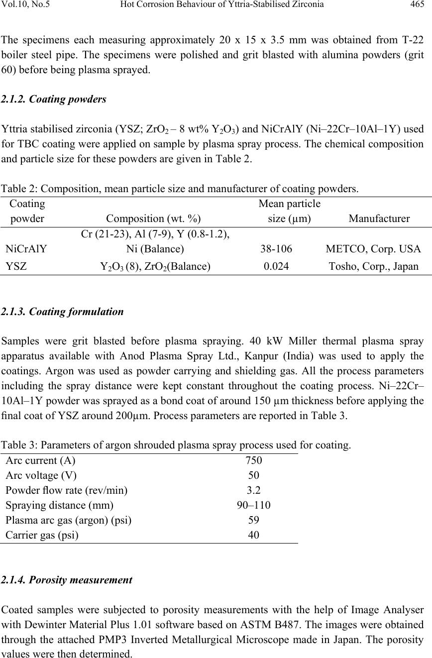 Vol.10, No.5 Hot Corrosion Behaviour of Yttria-Stabilised Zirconia 465 The specimens each measuring approximately 20 x 15 x 3.5 mm was obtained from T-22 boiler steel pipe. The specimens were polished and grit blasted with alumina powders (grit 60) before being plasma sprayed. 2.1.2. Coating powders Yttria stabilised zirconia (YSZ; ZrO2 – 8 wt% Y2O3) and NiCrAlY (Ni–22Cr–10Al–1Y) used for TBC coating were applied on sample by plas ma spray process. The chemical composition and particle size for these powders are given in Table 2. Table 2: Composition, mean particle size and manufacturer of coating powders. Coating powder Composition (wt. %) Mean particle size (µm) Manufacturer NiCrAlY Cr (21-23), Al (7-9), Y (0.8-1.2), Ni (Balance) 38-106 METCO, Corp. USA YSZ Y2O3 (8), ZrO2(Balance) 0.024 Tosho, Corp., Japan 2.1.3. Coating formulation Samples were grit blasted before plasma spraying. 40 kW Miller thermal plasma spray apparatus available with Anod Plasma Spray Ltd., Kanpur (India) was used to apply the coatings. Argon was used as powder carrying and shielding gas. All the process parameters including the spray distance were kept constant throughout the coating process. Ni–22Cr– 10Al–1Y powder was sprayed as a bond coat of around 150 µm thickness before apply ing the final coat of YSZ around 200µm. Process parameters are reported in Table 3. Table 3: Parameters of argon shrouded plasma spray process used for coating. Arc current (A) 750 Arc voltage (V) 50 Powder flow rate (rev/min) 3.2 Spraying distance (mm) 90–110 Plasma arc gas (argon) (psi) 59 Carrier gas (psi) 40 2.1.4. Porosity measurement Coated samples were subjected to porosity measurements with the help of Image Analyser with Dewinter Material Plus 1.01 software based on ASTM B487. The images were obtained through the attached PMP3 Inverted Metallurgical Microscope made in Japan. The porosity values were then determined.  466 Dinesh Gond, D. Puri, S. Prakash Vol.10, No.5 2.2. High Temperature Oxidation Study in Air and Salt Hot corrosion studies were conducted at 900°C in laboratory using a silicon carbide tubular furnace with PID temperature controller (make Digitech, India). The bare samples were subjected to mirror polishing including cloth polish. Accurate dimensions were taken by digital vernier (make Mototoy o, Japan) to calculate the area of the sample. Finally s pecimens were cleaned i.e. degreased by ethanol and kept in an alumina boat. Prior to the experiment, alumina boat was kept in the oven for 5hr at 250°C and then moved into the furnace at 900°C for 2hr to expel all the moisture. After this for hot corrosion behaviour in air, sa mples of T-22 bare and YSZ coated steel were kept in an alumina boat and then inserted in the tubular furnace for 1 hr at 900°C and removed to cool further for 20 minutes to room temperature and their weights were measured. In case of hot corrosion in the given salt environment of 75%wt Na2SO4 + 25%wt NaCl for bare and as sprayed samples each cycle consisted of 1hr of heating at 900 °C followed by 20min cooling at room temperature. The coating of uniform thickness with 3–5mg/cm2 of 75%wt Na2SO4 + 25%wt NaCl was applied with camel hairbrush on the preheated samples (250°C). After the salt application, the samples were kept in an oven for 2½hr at 250°C and then cyclic oxidation test was carried out on samples. The samples were subjected to weight change measurements after visual observations at the end of each cycle. Weights of the samples were taken using an Electronic Balance Model CB-120 (Contech, Mumbai, India) with a sensitivity of 0.001 gms. Burnt scales which were spalled out in boat were also taken into consideration i.e. the weight was taken along with the boat. This cycle was repeated for 50 times i.e. 50 cycles were made for each sample. Corroded samples from air and salt environment were analysed by XRD (BRUKER-binary V3) and SEM/EDAX and the oxide scales that fell into the boat were also analysed by XRD. Cu radiation was used in XRD at a step of 2°/min and the range of angle was 5-100°. 3. EXPERIMENTAL RESULTS 3.1. Behaviour in Air and Salt at Elevated Temperature The weight gain plots for bare sample and coated samples are shown in Fig. 1 in the presence of air and salt layer of 75%wt Na2SO4 + 25%wt NaCl at 900°C. On x-axis “number of cycles” and on y-axis “weight gain/area (mg/cm2)” was taken. In case of air oxidation, hot corrosion behaviour of T-22 bare steel in air was parabolic but oxidation rate of T-22 YSZ coated sample was too less i.e. nearly 88.45% less as compared to bare steel. In case of salt oxidation, T-22 bare steel behaviour was parabolic but after 35th cycle there was more weight gain and T-22 YSZ coated sample showed more resistance t o oxidation than th e bare sample i.e. nearly 89.47% less as compared to bare steel. The graph reveals that T-22 YSZ coated steel is better than T-22 bare steel in an environment of air and salt for 50 cycles. The behaviour of YSZ coated steel was almost constant in an environment of air and salt, which can be clearly seen from Fig.1 and Fig.2.  Vol.10, No.5 Hot Corrosion Behaviour of Yttria-Stabilised Zirconia 467 Fig. 2 shows graph of (Weight gain/area)2 vs. Number of cycles. In this graph every curve is associated with straight line of same colour. This straight line is trend line and it is used to calculate rate constant (Kp) which is given in Table 4. Fig 1. Weight gain vs. number of cycles plotted for Fig 2. (Weight gain/area) 2 vs. number of cycles plot Coated and uncoated T-22 steel subjected to cyclic for coated and uncoated T-22 steel subjected t o oxidation for 50 cycles in air and salt at 900°C. cyclic oxidation for 50 cycles in air and salt at 900°C Every line or curve in graph has an approximate equation which is given below. For T-22 bare air oxidised sample the approximated curve equation is Y= 0.83553 + 5.19553 *X - 0.05014 *X^2 For T-22 YSZ coated air oxidised sample, the approxi mated curve equation is Y= -2.07414 + 0.42323 *X - 9.92824E-4 *X^2 For T-22 bare salt oxidised sample, the approximated curve equation is Y= 18.71812 + 2.49238 *X - 0.00495 *X^2 For T-22 YSZ coated salt oxidised sample, the approxi mated curve equation is Y= 0.21895 + 0.20559 *X + 0.00222 *X^2 (Where X is number of cycle and Y is weight gain/area & these equation are calculated by using analysis mode of Origin software) Table 4: Value of the rate constant Kp for T-22 bare and coated specimens Description Kp (10-6 g2 cm -4 s-1) T-22 bare air oxidised 119 T-22 bare salt oxidised 100 T-22 YSZ coat ed air oxidised 1.6 T-22 YSZ coated salt oxidised 0.2 As shown in macrograph Fig.3 (a) cracks in the scale were observed for the hot corrosion runs for T-22 bare air oxidised sample and in case of T-22 bare salt oxidised sample its oxide  468 Dinesh Gond, D. Puri, S. Prakash Vol.10, No.5 layer got separated from its substrate in form of layers but were partially adhered to substrate as is evident from Fig.3 (b). In case of T-22 YSZ coated air oxidised sample Fig.3 (c) single crack in top layer is observed and in case of T-22 YSZ coated salt oxidised sample Fig.3 (d) cracks did not occurred in coating so there was no corrosion at the substrate. (a) (b) (c) (d) Fig. 3 Macrograph of (a) T-22 bare air oxidised (b) T-22 bare salt oxidised (c) T-22 YSZ coated air oxidised (d) T-22 YSZ coated salt oxidised. 3.2. X-Ray Diffraction Analysis The samples and their scales after oxidation were removed from boat and were analysed separately by XRD. After this, only oxidised sample were analysed by SEM /EDAX. The results of XRD analysis contained graph indicating peak values (i.e. d values) which were used to identify various phases with the help of inorganic X-ray Diffraction data card from Powder diffraction file of JCP DS. Help of Philips X ’ pert High score software was also taken for finding out compounds at respective peaks. 3.2.1. XRD result for T-22 bare and YSZ coated air and salt oxidised sample. From the X-Ray Diffraction analysis, it is found that ferrous oxide (Fe2O3), chromium oxide (Cr2O3), nickel oxide (NiO) are mainly formed along with chromium ferrous oxide (Cr, Fe)2O3 in T-22 bare air oxidised samples Fig.4 (C and D) and T-22 salt oxidised sample Fig. 5 (B and C) . Fe2O3, Cr2O3 form a protective oxide layer at surface due to which further oxidation is prevented as it acts as barrier for further corroding media to interact with substrate but at initial st age as the substrate material w as in direct contact of corroding media so there was accelerated corrosion at initial stage. In case of T-22 steel, Nickel oxide (NiO) is formed which are not protective, rathe r than that NiO is said to be loose structured and thus lead to more pore size and thus results in more corrosion [15]. In case of coat ed samples the cas e of acceler ated corrosion at in iti al stage was absent due to the overlay coating of yttria stabilised zirconia (YSZ). In T-22 YSZ coated air oxidised sample Fig. 4(A and B) and T-22 YSZ coated salt oxidised sample Fig. 5 (A) there is formation of mainly ZrO2, Y2ZrO3 and in case of YSZ coated salt oxidised sample apart from this an extra phase of ZrS is also formed.  Vol.10, No.5 Hot Corrosion Behaviour of Yttria-Stabilised Zirconia 469 Fig. 4 XRD patterns for T-22 steel subjected to cyclic oxidation in air at 900°C after 50 cycles. (A)T-22 YSZ coated sputtered scales (B) T-22 YSZ coated sample (C) T-22 bare sputtered scales (D) T-22 bare sample. Fig. 5 XRD patterns for T-22 steel subjected to cyclic oxidation in salt at 900°C after 50 cycles. (A) T-22 YSZ coated sample (B) T-22 bare sputtered scales (C) T-22 bare sample.  470 Dinesh Gond, D. Puri, S. Prakash Vol.10, No.5 3.3. Energy Dispersive X-ray (EDAX) Studies 3.3.1. Surface scale morphology The SEM/EDAX analysis for T-22 bare sample after oxidation in air for 50 cycles at 900°C is shown in Fig. 6(a). The SEM micrograph for corroded T-22 air oxidised steel indicate a scale with growth from inside having more amount of Mo when point analysis was taken in crack as compare to other spots and the scale has got cracked from middle. The s cale showed very high percentage of Fe and O as compared to chromium and this reveals that oxide layer formed mainly comprises of Fe2O3 and Mo2O3. EDAX analysis of T-22 YSZ coated air oxidised sample Fig. 6(b) shows high amount of Zr, O and Y which reveals the formation of ZrO2 and Y2O3 which prevented the oxidizing media to interact directly with substrate and at some spot iron was also revealed. In case of salt oxidised condition surface morphology of T-22 bare salt oxidised sample Fig. 6(c) revealed some fibrous structure at higher magnification which mainly comprised of Fe2O3 and the rest other compounds were Mo2O3, Cr2O3 and NiO and at very middle nodule of aluminium oxide was also found while in case of T-22 YSZ coated salt o xidised s ample Fig. 6(d) reveals the formation of ZrO2 and Y2O3 as in case of air oxidised sample. 3.3.2. Cross-sectional scale morphology In T-22 bare air oxidised sample Fig. 7(a) at point 3 where the oxide layer has got separated from substrate shows decrease in elemental composition but at outer side i.e. at point 12 there is more ferrous and at point 1 there is no oxygen but high amount of ferrous as it is substrat e material whereas there is a continuous increase in oxygen from point 4 till the end. In T-22 salt oxidised sample Fig. 7(b) after point 3 where the oxide layer has got bit separated from substrate shows decrease in elemental composition of ferrous but at outer side i.e. at point 9 there is more ferrous and at point 1 there is no oxygen but high amount of ferrous as it is substrate material and at point 4 where there is void less amount of ferrous oxide has been found as compared to other points. In this outer oxide layer seems to be thick. Cross sectiona l analysis of T-22 YSZ coated air oxidised sample Fig. 7(c) shows that at point 2 where the bond coat starts ferrous steeply decreased and nickel increased due to presence of bond coat and from 5 content of zirconium increased due to presence of top coat. In case of T-22 YSZ coated salt oxidised s ample Fig. 7(d) same condition o ccurred as that of T-22 YSZ coated air oxidised sample the main difference was that in this zirconium started increasing from point 7. In T-22 YSZ coated air oxidised and T-22 YSZ coated salt oxidised condition weight % of oxygen was very low.  Vol.10, No.5 Hot Corrosion Behaviour of Yttria-Stabilised Zirconia 471 (a)T-22 bare air oxidised sample at scale of 100µm (b)T-22 YSZ coated air oxidised sample at scale of 50µm (c)T-22 bare salt oxidised sample at scale of 100µm (d)T-22 YSZ coated salt oxidised sample at scale of 50µm Fig. 6 Surface scale morphology and EDAX analysis (wt%) for T-22 bare and YSZ coated sample subjected to the cyclic oxidation at 900°C for 50 cycles in 75 wt.% Na2SO4 + 25 wt.% NaCl salt.  472 Dinesh Gond, D. Puri, S. Prakash Vol.10, No.5 (a) T-22 bare air oxidised sample (b) T-22 bare salt oxidised sample (c) T-22 YSZ coated air oxidised sample (d) T-22 YSZ coated salt oxidised sample Fig. 7 Oxide scale morphology and elemental composition variation across the cross section of T-22 bare and YSZ coated sample exposed to air and salt environment at 900°C for 50 cycles.  Vol.10, No.5 Hot Corrosion Behaviour of Yttria-Stabilised Zirconia 473 3.3.3. X-Ray mapping X-ray mapping analysis of T-22 bare air oxidised sample is shown in Fig. 8. The micrograph indicates that oxide layer has got separated from substrate and from where it starts a thin dense layer of chromium are present and the dense layer of ferrous starts from then onwards till the end while dense oxygen layer is present in all over oxide scale region. X-ray mapping analysis of T-22 bare salt oxidised sample is shown in Fig. 9. In this dense layer of ferrous, chromium and oxygen is present in region of oxide scale. In X-ray mapping analysis voids are visible in oxide scale region of Fe and O mapping micrograph but chromium macrograph shows uniform distribution in voids also. X-ray mapping analysis of T-22 YSZ coated air oxidised sample is shown in Fig. 10. In this it is clearly revealed from Fe mapping micrograph that no oxidizing media was able to interact directly with substrate material due to presence of bond coat and top coat. Along with Zr layer Fe and O is seen at surface while in this a dense layer of nickel, chromium, aluminium and light layer of yttrium is seen at centre in bo nd co at reg i on. Dense l ayer of zirconium and yttrium can be seen at surfac e in top coat region. Fig.8 BSEI and elemental X-ray mapping of the cross-section of T-22 bare sample exposed to cyclic hot corrosion in air at 900°C for 50 cycles. BSEI Substrate Oxide Cr Fe Mn Mo Ni O  474 Dinesh Gond, D. Puri, S. Prakash Vol.10, No.5 Fig. 9 BSEI and elemental X-ray mapping of the cross-section of T-22 bare sample exposed to cyclic hot corrosion in salt at 900°C for 50 cycles. X-ray mapping analysis of T-22 YSZ coated salt oxidised sample is shown in Fig. 11. In this X-ray mapping analysis micrograph reveals dense layer of zirconium and oxygen at surface and in between the zirconium layer ferrous and aluminium can be seen. Dense lay er of nick el, chromium, aluminium is seen in region of bond coat. 4. DISCUSSION Internal oxidation led to the cracking of the scale due to the different thermal expansion coefficients of oxides in the scale from that of coating as suggested by P. Niranatlumpong [14]. This has further been supported by the findings of R.A. Rapp and P.S.Liu [16-17], where it has been observed that development of stresses is due to difference in thermal expansion coefficients. As there are various elements and each have different thermal coefficient of expansion hence there will be more stress generated which will lead to more cracking. Through these cracks, corrosive gases can penetrate to the base material and will thus allow significant grain boundary corrosion attack [18-20]. Substrate Oxide BSEI Cr Ni Fe O Mn Mo  Vol.10, No.5 Hot Corrosion Behaviour of Yttria-Stabilised Zirconia 475 Fig. 10 BSEI and elemental X-ray mapping of the cross-section of T-22 YSZ coated air oxidised sample exposed to cyclic hot corrosion at 900°C for 50 cycles. Extrusion of materials from beneath and oxide protrusions are believed to be due to the greater specific volume of oxides similar to the findings of N.S. Bornstein [21]. Weight gain in case of T-22 steels might be attributed to the presence of molybdenum in substrate steel. U.K. Chatterjee [22] has proposed that the cracking of the scale results from the enrichment by Mo at the su bstrate scale int erface , where MoO 2 is f or med . Thi s ox ide co nv er ts i nto Mo O3 on further oxidation, which is in liquid form at the given temperature of exposure and penetrates along the alloy scale interface. MoO3 further reacts with Na2SO4 to form low melting point Na2MoO4 and SO3 gas contribute to further generation of cracks. The concentration of M o at the interface will increase as the o ther alloying elements ar e oxidised and this MoO3 gets evaporated at the melt–gas interface. During investigation, the NiO layer was observed in the oxide scale of T-22 steel. This layer has been suggested to be loose- structured which may not be able to provide effective protection and increase in the p ore size of Ni and Cr scale with increase in exposure time, which allows the degrading species to penetrate through the coating thereby resulting in the oxidation of substrate steels [15]. However, once the oxides are formed at the places of the porosity and the grain boundaries, the oxide layer becomes dense and the diffusion of the oxidizing species to the internal Cr Ni Y Mo Zr O Fe Al BSEI Substrate Coating  476 Dinesh Gond, D. Puri, S. Prakash Vol.10, No.5 portions of the substrate gets slowed down and the growth of the oxides becomes limited mainly to the surface of the specimens. Zirconia-based TBCs require alloying oxides such as Y2O3, CaO, CeO, MgO, etc., in order to stabilize a single-phase material, usually in the tetragonal form [22]. At room temperature the equilibrium phases of yttria partially stabilized zirconia are expected to be a low yttria content monoclinic phase and a high yttria content cubic phase. However, due to rapid cooling during the plasma-spraying process, formation of a non-equilibrium tetragonal phase takes place [22-24]. Fig. 11 BSEI and elemental X-ray mapping of the cross-section of T-22 YSZ coated sample exposed to cyclic hot corrosion at 900°C for 50 cycles in salt of 75 wt.% Na2SO4 + 25 wt.% NaCl. Y O Zr Ni Na Mo Cr Fe Al BSEI Substrate Coating  Vol.10, No.5 Hot Corrosion Behaviour of Yttria-Stabilised Zirconia 477 A possible hot corrosion mechanism in zirconia-based TBCs can be divided into three steps. The first step is salt & other corroding media penetration into the entire thickness of the zirconia top coating layer through splat boundaries and other coating defects such as microcracks and open pores. This step is accomplished very fast. The second step is the reaction of penetrated salts & other corroding media with tetragonal stabilizers in zirconia. Because each zirconia splat is surrounded by the corroding media in the entire area of the zirconia coating layer, the depletion of stabilizers in zirconia and consequent phase transformation to monoclinic can occur in a very rapid and effective manner. Because of the volume expansion effect, accompanied with monoclinic phase transformation, results in unexpected failure under thermal shock conditions with a corrosive environment, this step is crucial and should be carefully considered, especially in the case of YSZ TBC systems. The final step is macroscale damage by diffusion controlled salt attacks. The failure of YSZ is due to transformation of zirconia to fully monoclinic, which can be retarded or prevented by using more acidic stabilizers [25].The results which were seen till now shows that YSZ coating is very much effective in providing protection from high temperature corrosion in case of both air and 75 wt. % Na2SO4 + 25 wt. % NaCl salt environment. In case of YSZ coated salt oxidised sample cracking was not observed till the end of 50 cycles whereas it occurred in YSZ coated air oxidised sample. 5. CONCLUSION The measured porosity value of plasma sprayed coating was 0.57% and this YS Z coated lay er has provided very high resistance to corrosion and thereby increasing their workable life as compared to bare sample subjected to corrosion in both condition i.e. air and 75 wt.% Na2SO4 + 25 wt.% NaCl salt environment. The cyclic oxidation of T-22 bare steel in air follow parabolic law and it has formed mainly hematite (Fe2O3) at top surface along with some NiO. In case of T-22 bare steel in salt oxidised sample weight gain follows parabolic law but after 35th cycle it showed steep increase in weight gain. Cyclic oxidation of T-22 YSZ coated air oxidised sample resulted in very fine cracking of coating but then to also the corrosion rate was too less as compared to bare sample and in case of T-22 YSZ coated salt oxidised sample cracking did not occurred. In T-22 YSZ coated salt oxidised sample an extra phase of ZrS was revealed from XRD analysis . The oxidation rate of T-22 YSZ coated air oxidised sample was too less i.e. nearly 88.45% less as compared to bare steel and in case of T-22 YSZ coated salt oxidised sample more resistance to oxidation than the bare sample was achieved i.e. nearly 89.47% less weight gain as compared to bare sample at 900° C for 50 cycles. REFERENCES [1] Lai G Y, Pub. ASM International (1990) Chapter 3, 15. [2] Harpreet Singh, D. Puri, S. Prakash, Surf. Coat. Technol. 192 (2004) 27– 38. [3] K.G. Bundinski, Surface Engineering for Wear Resistance, Prentice-Hall, New Jersey, 1988.  478 Dinesh Gond, D. Puri, S. Prakash Vol.10, No.5 [4] M.K. Hobbs, H. Reiter, Residual stresses in ZrO2–8%Y2O3 plasma sprayed thermal barrier coatings, in: D.L. Houck (Ed.), Thermal Spray: Advances in Coatings Technology, ASM International (1989) 285–290. [5] H. Herman, C.C. Berndt, H. Wang, Plasma sprayed ceramic coatings, in: J.B. Wachtman, R.A. Haber (Eds.), Ceramic Films and Coatings, Noyes Publications, New Jersey, (1993). [6] L. Pawlowski, The Science and Engineering of Thermal Spray Coatings, Wiley, New York, (1995). [7] A.G. Evans, D.R. Mu mm, J.W. Hutchinson, G.H . Meier, F.S. Pettit, Prog. Mater. Sci. 46 (2001) 505. [8] J.R. Brandon, R. Taylor, Surf. Coat. Techol. 69 (10) (1992) 75. [9] I. Gurrappa, J. Mater. Sci. Lett. 17 (1998) 1267. [10] R.L. Jones, J. Therm. Spray Technol. 6 (1) (1997) 77. [11] B.A. Nagaraj, D.J. Wortman, Trans. ASME 112 (1990) 536. [12] R. Srinivasan, J.M. Merrilea, Surf. Coat. Technol. 160 (2002) 187. [13] R.L. Jones, J. Am. Ceram. Soc. 75 (7) (1992) 1818. [14] P. Niranatlumpong, C.B. Ponton, H.E. Evans, Oxid. Met. 53 (3–4) (2000) 241. [15] Buta Singh Sidhu, S. Prakash, Surf. Coat. Technol. 201 (2006) 1643–1654. [16] R.A. Rapp, J.H. Devan, D.L. Douglass, P.C. Nordine, F.S. Pettit, D.P.Whittle, Mater. Sci.Eng.50 (1981) 1. [17] P.S. Liu, K.M. Liang, H.Y. Zhou, S.R. Gu, X.F. Sun, H.R. Guan, T. Jin, K.N. Yang, Surf. Coat. Technol. 145 (2001) 75. [18] Kimura K, Kushima H, Abe F, Yagi K, Irie H. In: Strang A, Banks WM, Conroy RD, Goulette MJ, “Advances in turbine materials, design and manufacturing”. London: The Institute of Materials, (1997) 257–69. [19] J.C. Van Wortel, C.F. Etienne, F. Arav, “Application of modified 9chromium steels in power generation components, in: VDEh ECSC Information Day, The Manufacture and Properties of Steel 91 for the Power Plant and Process Industries”, Dusseldorf, (1992) 4.2. [20] J. Orr, A. Di Gianfrancesco, “The effect of compositional variations on the properties of steel 91, in: VDEh ECSC Information Day, The Manufacture and Properties of Steel 91 for the Power Plant and Process Industries”, Dusseldorf, (1992) 2.4. [21] N.S. Bornstein, M.A. Decrescente, H.A. Roth, MMIC-75-27, Columbus, Ohio, USA, (1975) 115. [22] C. Batista, A. Portinha, R.M. Ribeiro, V. Teixeira, C.R. Oliveira, Surf. Coat. Technol. 200 (2006) 6783–6791. [23] R.A.Miller, R.G. Garlick, J.L. Smialek, Ceram. Bull. 62 (12) (1983) 1355. [24] A.N. Khan, J. Lu, H. Liao, Mater. Sci. Eng., A Struct. Mater.: Prop.Microstruct. Process. 359 (2003) 129. [25] S.Y. Park, J.H. Kim, M.C. Kim, H.S. Song, C.G. Park, Surf. Coat. Technol.190 (2005) 357-365. |