Paper Menu >>
Journal Menu >>
 Journal of Minera ls & Materials Ch ar ac teri zatio n & Engineeri ng, Vol. 10, No.4, pp.387-396, 2011 jmmce.org Printed in the USA. All rights reserved 387 Influence of Mould Heat Storage Capacity on Properties of Grey Iron A.V. Adedayo 1,3 and B. Aremo 2 1Department of Materials Science and Engineering, Obafemi Awolowo University, Ile-Ife, Nigeria 2Centre for Energy Research and Development (CERD), Obafemi Awolowo University, Ile-Ife, Nigeria 3Department of Metallurgical Engineering, Kwara State Polytechnic, PMB 1375, Ilorin, Nigeria Corresponding Author: adelekeadedayo58@yahoo.com ABSTRACT Grey cast iron is characterized by presence of a large portion of its carbon in the form of graphite flakes which are observable in their microstructures. Their properties are significantly dependent on the micro-constituents of the, cast iron components. A way of controlling the microstructure of cast iron is through the controlled cooling rates during solidification. To control cooling rate, the heat storage capacity of the mould is important. This paper presents the characteristic effects of graphite flake sizes on some mechanical properties of grey cast iron. Six mould materials with heat storage capacities ranging from 1.52 kJ.m-2.K-1.s-1/2 to 2.16 kJ.m-2.K-1.s-1/2 were prepared and used to cast some grey cast ir on samples whose microstructures were observed by optical microscopy. Mechanical properties of the grey iron were evaluated. The results show that the properties increased with the heat storage capacity of the mould. Also, the microstructures show a dependence on heat storage capacity of the mould. Keywords: Graphite, Heat storage capacity, Cementite, Grey Iron, Graphite flakes 1. INTRODUCTION Cast Irons (C.I.) normally contain 2-4 wt% of carbon with a high silicon concentration [1-4] and a greater concentration of impurities than steels. The carbon equivalent (CE) of a C.I. helps to identify the grey irons which cool into a microstructure containing graphite and the white irons where the carbon is present mainly as iron carbide and is then referred to as combined carbon - cementite. The carbon equivalent (CE) is defined as: 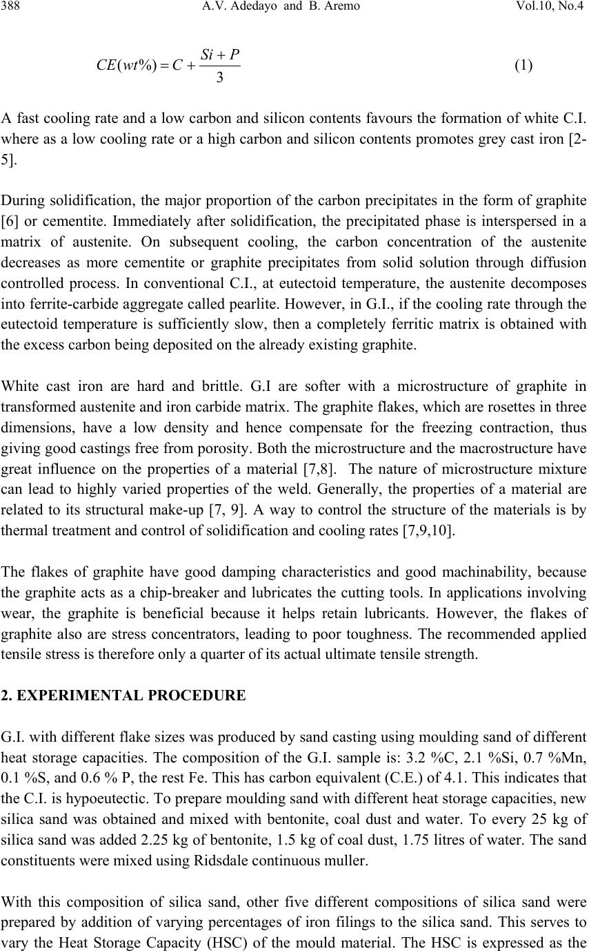 388 A.V. Adedayo and B. Aremo Vol.10, No.4 3 %)( PSi CwtCE (1) A fast cooling rate and a low carbon and silicon contents favours the formation of white C.I. where as a low cooling rate or a high carbon and silicon contents promotes grey cast iron [2- 5]. During solidification, the major proportion of the carbon precipitates in the form of graphite [6] or cementite. Immediately after solidification, the precipitated phase is interspersed in a matrix of austenite. On subsequent cooling, the carbon concentration of the austenite decreases as more cementite or graphite precipitates from solid solution through diffusion controlled process. In conventional C.I., at eutectoid temperature, the austenite decomposes into ferrite-carbide aggregate called pearlite. However, in G.I., if the cooling rate through the eutectoid temperature is sufficiently slow, then a completely ferritic matrix is obtained with the excess carbon being deposited on the already existing graphite. White cast iron are hard and brittle. G.I are softer with a microstructure of graphite in transformed austenite and iron carbide matrix. The graphite flakes, which are rosettes in three dimensions, have a low density and hence compensate for the freezing contraction, thus giving good castings free from porosity. Both the microstructure and the macrostructure have great influence on the properties of a material [7,8]. The nature of microstructure mixture can lead to highly varied properties of the weld. Generally, the properties of a material are related to its structural make-up [7, 9]. A way to control the structure of the materials is by thermal treatment and control of solidification and cooling rates [7,9,10]. The flakes of graphite have good damping characteristics and good machinability, because the graphite acts as a chip-breaker and lubricates the cutting tools. In applications involving wear, the graphite is beneficial because it helps retain lubricants. However, the flakes of graphite also are stress concentrators, leading to poor toughness. The recommended applied tensile stress is therefore only a quarter of its actual ultimate tensile strength. 2. EXPERIMENTAL PROCEDURE G.I. with different flake sizes was produced by sand casting using moulding sand of different heat storage capacities. The composition of the G.I. sample is: 3.2 %C, 2.1 %Si, 0.7 %Mn, 0.1 %S, and 0.6 % P, the rest Fe. This has carbon equivalent (C.E.) of 4.1. This indicates that the C.I. is hypoeutectic. To prepare moulding sand with different heat storage capacities, new silica sand was obtained and mixed with bentonite, coal dust and water. To every 25 kg of silica sand was added 2.25 kg of bentonite, 1.5 kg of coal dust, 1.75 litres of water. The sand constituents were mixed using Ridsdale continuous muller. With this composition of silica sand, other five different compositions of silica sand were prepared by addition of varying percentages of iron filings to the silica sand. This serves to vary the Heat Storage Capacity (HSC) of the mould material. The HSC is expressed as the  Vol.10, No.4 Influence of Mould Heat Storage Capacity 389 root of the product of the thermal conductivity, the specific heat capacity and the density of the mould materials. i.e: ..cHSC (2) where λ is the thermal conductivity, c the specific heat capacity and ρ the density of the mould materials. For a mould made of different materials, a simple proportion formula was used to evaluate the resultant HSC i.e. iiiinetmulticompo cfHSC .. (3) where fi is the fraction of component i in a multi-component mould (see Tables 1 and 2). A control sample, which had no Fe content, was also prepared (see Table 3). Table 1: Standard composition of the green moulding sand Materials Weight composition (wt %) Silica sand 82 Bentonite 7 Coal dust 5 Water 6 Table 2: Physical properties of the mould materials Materials Thermal conductivity (W.m-1.K-1) Specific heat capacity (kJ.kg-1.K-1) Density (kg.m-3) Silica sand 0.657 2.01 1700 Bentonite 1.035 1.089 1850 Coal dust 0.186 1.31 1200 Water 0.551 4.212 999.9 Iron 63 0.502 7220 Table 3: Specimen with percentages and masses of Fe filings contents Mold material Percentage of Fe filings (wt%) Mass of Fe filings (kg) Heat storage capacity of the mould, HSC, (kJ.m-2.K-1.s-1/2 ) A - - 1.52 A1 1 0.3 1.65 A2 2 0.6 1.77 A3 3 0.9 1.90 A4 4 1.2 2.03 A5 5 1.5 2.16 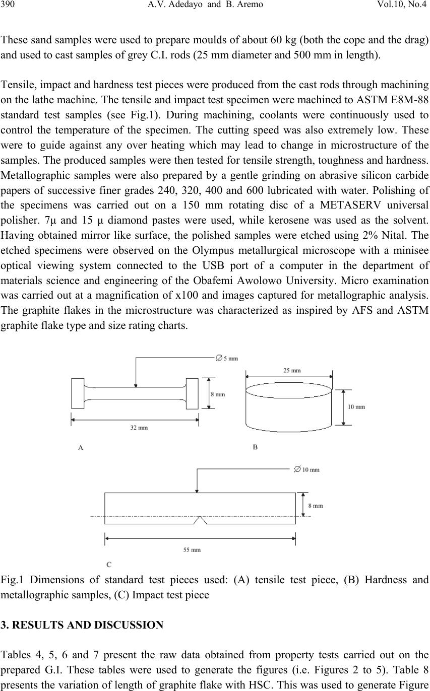 390 A.V. Adedayo and B. Aremo Vol.10, No.4 These sand samples were used to prepare moulds of about 60 kg (both the cope and the drag) and used to cast samples of grey C.I. rods (25 mm diameter and 500 mm in length). Tensile, impact and hardness test pieces were produced from the cast rods through machining on the lathe machine. The tensile and impact test specimen were machined to ASTM E8M-88 standard test samples (see Fig.1). During machining, coolants were continuously used to control the temperature of the specimen. The cutting speed was also extremely low. These were to guide against any over heating which may lead to change in microstructure of the samples. The produced samples were then tested for tensile strength, toughness and hardness. Metallographic samples were also prepared by a gentle grinding on abrasive silicon carbide papers of successive finer grades 240, 320, 400 and 600 lubricated with water. Polishing of the specimens was carried out on a 150 mm rotating disc of a METASERV universal polisher. 7μ and 15 μ diamond pastes were used, while kerosene was used as the solvent. Having obtained mirror like surface, the polished samples were etched using 2% Nital. The etched specimens were observed on the Olympus metallurgical microscope with a minisee optical viewing system connected to the USB port of a computer in the department of materials science and engineering of the Obafemi Awolowo University. Micro examination was carried out at a magnification of x100 and images captured for metallographic analysis. The graphite flakes in the microstructure was characterized as inspired by AFS and ASTM graphite flake type and size rating charts. Fig.1 Dimensions of standard test pieces used: (A) tensile test piece, (B) Hardness and metallographic samples, (C) Impact test piece 3. RESULTS AND DISCUSSION Tables 4, 5, 6 and 7 present the raw data obtained from property tests carried out on the prepared G.I. These tables were used to generate the figures (i.e. Figures 2 to 5). Table 8 presents the variation of length of graphite flake with HSC. This was used to generate Figure 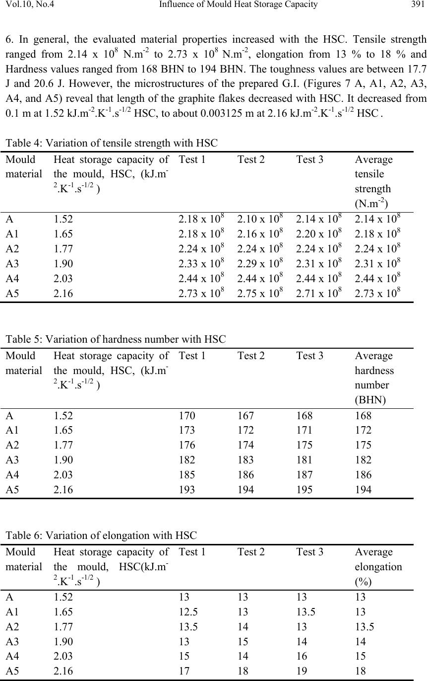 Vol.10, No.4 Influence of Mould Heat Storage Capacity 391 6. In general, the evaluated material properties increased with the HSC. Tensile strength ranged from 2.14 x 10⁸ N.m-2 to 2.73 x 10⁸ N.m-2, elongation from 13 % to 18 % and Hardness values ranged from 168 BHN to 194 BHN. The toughness values are between 17.7 J and 20.6 J. However, the microstructures of the prepared G.I. (Figures 7 A, A1, A2, A3, A4, and A5) reveal that length of the graphite flakes decreased with HSC. It decreased from 0.1 m at 1.52 kJ.m-2.K-1.s-1/2 HSC, to about 0.003125 m at 2.16 kJ.m-2.K-1.s-1/2 HSC . Table 4: Variation of tensile strength with HSC Mould material Heat storage capacity of the mould, HSC, (kJ.m- 2.K-1.s-1/2 ) Test 1 Test 2 Test 3 Average tensile strength (N.m-2) A 1.52 2.18 x 10⁸ 2.10 x 10⁸ 2.14 x 10⁸ 2.14 x 10⁸ A1 1.65 2.18 x 10⁸ 2.16 x 10⁸ 2.20 x 10⁸ 2.18 x 10⁸ A2 1.77 2.24 x 10⁸ 2.24 x 10⁸ 2.24 x 10⁸ 2.24 x 10⁸ A3 1.90 2.33 x 10⁸ 2.29 x 10⁸ 2.31 x 10⁸ 2.31 x 10⁸ A4 2.03 2.44 x 10⁸ 2.44 x 10⁸ 2.44 x 10⁸ 2.44 x 10⁸ A5 2.16 2.73 x 10⁸ 2.75 x 10⁸ 2.71 x 10⁸ 2.73 x 10⁸ Table 5: Variation of hardness number with HSC Mould material Heat storage capacity of the mould, HSC, (kJ.m- 2.K-1.s-1/2 ) Test 1 Test 2 Test 3 Average hardness number (BHN) A 1.52 170 167 168 168 A1 1.65 173 172 171 172 A2 1.77 176 174 175 175 A3 1.90 182 183 181 182 A4 2.03 185 186 187 186 A5 2.16 193 194 195 194 Table 6: Variation of elongation with HSC Mould material Heat storage capacity of the mould, HSC(kJ.m- 2.K-1.s-1/2 ) Test 1 Test 2 Test 3 Average elongation (%) A 1.52 13 13 13 13 A1 1.65 12.5 13 13.5 13 A2 1.77 13.5 14 13 13.5 A3 1.90 13 15 14 14 A4 2.03 15 14 16 15 A5 2.16 17 18 19 18  392 A.V. Adedayo and B. Aremo Vol.10, No.4 Table 7: Variation of toughness with HSC Mould material Heat storage capacity of the mould, HSC(kJ.m- 2.K-1.s-1/2 ) Test 1 Test 2 Test 3 Average toughness (J) A 1.52 18 18 17 17.7 A1 1.65 18 17 19 18 A2 1.77 17 18 20 18.3 A3 1.90 19 18 19 18.6 A4 2.03 21 20 20 20.3 A5 2.16 20 21 21 20.6 Table 8: Variation of length of graphite flake with HSC Mould material Heat storage capacity of the mould, HSC, (kJ.m-2.K-1.s-1/2 ) Length of graphite flakes (m) A 1.52 0.05 to 0.1 A1 1.65 0.025 to 0.05 A2 1.77 0.025 to 0.05 A3 1.90 0.0125 to 0.025 A4 2.03 0.00625 to 0.0125 A5 2.16 0.003125 to 0.00625 1.9 2 2.1 2.2 2.3 2.4 2.5 2.6 2.7 2.8 1.4 1.61.822.2 HSC (kJ.m-2.K-1.s-1/2 ) Tensile strength (x 10^8 N.m- 2 Test 1Test 2Test 3Average Figure 2: Variation of tensile strength with HSC  Vol.10, No.4 Influence of Mould Heat Storage Capacity 393 165 170 175 180 185 190 195 200 1.4 1.61.822.2 HSC (kJ.m-2.K-1.s-1/2 ) Hardness (BHN ) Test 1Test 2Test 3Average Figure 3: Variation of hardness number with HSC 0 2 4 6 8 10 12 14 16 18 20 1.4 1.61.822.2 HSC (kJ.m-2.K-1.s-1/2 ) Elongation (% ) Test 1Test 2Test 3Average Figure 4: Variation of elongation with HSC 0 5 10 15 20 25 1.4 1.61.822.2 HSC , (kJ.m-2.K-1.s-1/2 ) Toughness (J ) Test 1Test 2Test 3Average Figure 5: Variation of toughness with HSC  394 A.V. Adedayo and B. Aremo Vol.10, No.4 0 0.02 0.04 0.06 0.08 0.1 0.12 1.52 1.651.771.92.03 2.16 HSC (kJ.m-2.K-1.s-1/2 ) Length of graphite flakes ( m length of graphite flakes Figure 6: Variation of graphite flakes length with HSC Figure 7: Microstructures (x100) of G.I. cast by mould material A, A1, A2, A3, A4, and A5 respectively Generally, during solidification of G.I., primary austenite (γ) will separate out first until the eutectic temperature is reached. At eutectic temperature, eutectic consisting of austenite and graphite would form [1, 11]. This is due to the presence of sufficient silicon which increases the instability of cementite. The eutectic develops from nuclei and is in the form of approximately spherical particles known as eutectic cells. Graphite appears to be in the form of separate flakes, but in fact the eutectic cells are three dimensional and roughly spherical in  Vol.10, No.4 Influence of Mould Heat Storage Capacity 395 shape [11]. Rapid cooling, which produces a greater degree of under cooling initiates the formation of a greater number of eutectic cells and also more frequent branching in the eutectic graphite “leaves”, giving much finer graphite flakes. The smaller the eutectic cells, the finer the graphite flakes. This explains the observed trend in gradual change from coarse to fine graphite flakes in the microstructure. Also, if subsequent cooling proceed slowly enough, at the eutectoid transformation, instead of forming cementite (Fe3C), the carbon diffuses to the nearest graphite flake and precipitates there as additional graphite [12]. The rejection of carbon in the austenite phase is a process controlled by diffusion, which in turn, is temperature dependent. During graphitization, free carbon is precipitated in the iron or chemically combined carbon (Fe3C) is changed to free carbon (or graphite), thus leading to a reduction in quantity of cementite present in the G.I. microstructure. Actually, fine dispersion of iron carbide (Fe3C) can be responsible for straining ferrite matrix in G.I. which can lead to increased hardness and strength. Strengthening of bainitic structures has been reported to be due to straining of ferrite matrix by iron carbide [13]. Generally, a fast cooling rate promotes formation of cementite. This is due to suppression of the graphitization process. A slower cooling rate allows sufficient time for graphitization. This, most often lead to a mixed microstructure consisting of cementite and graphite [5]. A higher HSC value suppresses this carbon rejection process through rapid cooling. The iron content of the mould induced this change in HSC of the mould. Further more, the three dimensional graphite flakes that formed during eutectic reaction, dispersed in a matrix of ferrite, pearlite or other iron-based structures have no appreciable strength, they act essentially as voids in the structure. The pointed edges of the flakes act as preexisting notches or cracks initiation site[3, 14], thus giving the material a reduced strength. Fracture mechanics have identified a relationship between crack size and material properties [15]. In general, higher values of crack length lead to a reduced material strength. 4. CONCLUSION The research shows that the HSC of the mould has significant effects on the microstructure and properties of G.I. This suggests that HSC of a mould could be varied as required to effect changes in the microstructure, tensile strength, elongation, hardness and toughness of G.I. Also, the effects of graphite flake sizes on some G.I. mechanical properties give an inverse characteristic trend. ACKNOWLEDGEMENT Nigerian Machine Tools Limited, Osogbo, Osun State, Nigeria is acknowledged for assistance in mould preparation, melting and casting of the grey cast iron samples.  396 A.V. Adedayo and B. Aremo Vol.10, No.4 REFERENCES [1] Adedayo A.V. 2010 Effects of addition of iron filings to green moulding sand on the microstructure of grey cast iron. Journal of the Brazilian Society for Mechanical Sciences and Engineering, Vol. XXXII, No 2, pp 171-175 [2] Rajput R.K. 2006 Engineering materials and metallurgy, 1st ed. S. Chand & Co. New Delhi., pp 13, 28-31, 101 [3] DeGarmo E.P., Black J.T., Kosher R.A.2003 Material and processes in manufacturing 9th ed. John Wiley and Sons, New York, pp 60-100, 375 - 408, 1100-1123 [4] Heine R.W., Loper C.R., Rosenthal P.C. 2003 Principles of metal castings, 26th reprint, TMH ed. New York, pp 86. [5] Moffatt, W.G.; Pearsall, G.W.; Wulff, J. 1964 The structure and properties of materials, structure, vol.1, John Wiley and Sons, Brisbane, pp 134, 195 [6] Rajan T.V., Sharma C.P., Sharma A. 1988 Heat treatment principles and techniques, Prentice-Hall of India, Private Ltd, New Delhi, pp11-14, 289, 331. [7] Adedayo A.V., Ibitoye, S.A., Oyetoyan, O.A. 2010 Annealing heat treatment effects on steel welds. Journal of Mineral, Materials Characterization and Engineering, Vol. 9, No. 6 pp 601-611. [8] Imaev R.M., Imaev V.M., Khismatullin T.G. 2006Refinning of the microstructure of cast intermetallic alloy Ti-43% Al-X (Nb, Mo, B) with the help of heat treatment, Metallovedenie I Termicheskaya Obrabotka Metallov, No.2, pp 38-41 [9] Adedayo A.V. 2009a Effects of carbon content on steel welds. Journal of Research in Technology and Engineering Management, Vol. 2, No. 1 pp131-135 [10] Adedayo, A.V 2009b Effects of Iron Filings on the Properties of Green Moulding Sand, Proceedings of 2nd National Conference of Institute of Technology, Kwara State Polytechnic, Ilorin, Vol 2, No 1, pp45-49 [11] Higgins, R.A. 2004 Engineering metallurgy: Applied physical metallurgy. 6th ed. Viva books, New Delhi, pp 355, 356 [12] Flemings M.C. 1974 Solidification processing; Materials science and engineering series. McGraw-Hill New York. pp 184 [13] Brophy, J.H., Rose, R.M.; Wulff J., 1964 The structure and properties of materials, thermodynamics, vol.2, John Wiley and Sons, Brisbane, pp 113-114, 188-189 [14] DeGarmo E.P., Black J.T., Kosher R.A. 1999 Material and processes in manufacturing 8th ed. John Wiley and Sons, New York, pp 90-93,345-415, 1114 [15] Callister W.J. 1985 Materials science and engineering, an introduction. John Wiley & Sons, NY, pp 717 -731 |

