Paper Menu >>
Journal Menu >>
 Journal of Minera ls & Materials Ch ar ac teri zatio n & Engineeri ng, Vol. 10, No.3, pp.231-244, 2011 jmmce.org Printed in the USA. All rights reserved 231 Development of Iron Based Brake Friction Material by Hot Powder Preform Forging Technique used for Medium to Heavy Duty Applications Mohammad Asif *, K. Chandra, P.S. Misra Metallurgical and Materials Engineering Department, Indian Institute of Technology, Roorkee. Roorkee- 247667, India * Corresponding author: masifiitr@gmail.com ABSTRACT A promising friction material, Iron -based friction material, was prepared by powder metallurgy (PM) processing utilizing hot powder preform forging (near net-shape).The preparation of the product and its characterization are presented in this paper. These products are useful in heavy duty Military Aircraft applications such as AN-32. In order to eliminate costly environmental control systems to protect products during their high temperature processing (as is conventionally practiced employing hydrogen gas), the present investigation relies on carbon (mixed in the brake pad formulation) as reducing agent and high temperature oxidation resistant glassy coating (separately developed) applied over the product’s surface after cold compacting. After conducting an initial characterization such as hardness, density and Pin-on Disc tests, the samples were tested in sub-scale dynamometer under Rejected Take Off conditions. It was observed that the obtained density in the present investigation is higher than the reported density obtained by sintering route, and wear is on the lower side of the range as per the Aeronautical Standards. Optical metallography was used to investigate the microstructure of friction, interface and backing layer. It was observed that the distribution of ingredients in matrix was homogeneous. The results also indicate that the coefficient of friction is more stable, and wear is lower with respect to temperature rise. . Keywords: Forging, Powder Metallurgy, Friction material, brake pad 1. INTRODUCTION Friction materials which are made by powder metallurgical technique, have been widely used in commercial/fighter aircrafts; high speed trains; brakes; clutches and gear assemblies of different kinds of automobiles [1].  232 Mohammad Asif , K. Chandra, P.S. Misra Vol.10, No.3 The traditional powder metallurgical friction materials mainly include iron and copper based, which are prepared by pressing and sintering of metal powders with the addition of solid lubricants (BaSO4, Sb2S3) and abrasives. [2]. In recent years, the speed and load of vehicles and engineering machines have increased greatly, which brings forward higher requirements for friction materials [3]. So it is important to develop alternative approach with good combination of properties. Iron based friction materials, retain some metallic characteristics (stable thermal stability, and hardness), as well as some particular properties such as high density level, favorable oxidation and corrosion resistance [4]. In this paper, Iron, as the friction material matrix is chosen due of its stability under higher temperatures (1100oC) and can be applied under heavy duty dry operating conditions because of its high melting point and other improved properties which include strength, hardness, ductility, heat resistance and stability etc. [5]. Friction elements based on metallo-ceramic constituents contain number of materials such as metals, lubricants, abrasives etc. These are known for high strength, high temperature stability, oxidation resistance, high thermal conductivity, wear resistance, and fade resistance. The chemistry of the friction elements obviously becomes extremely complex because such expectations cannot be met with restricted number of constituents. In view of this, it becomes necessary to process these starting from powder mixture having different constituents in suitable proportions. Compacting and sintering technology [6] is one such technology through which these products are currently being made. However, it suffers from certain major limitations such as inadequate joining of friction element with backing plate, poor density levels achieved in friction element owing to limited application of pressure during compacting, poor thermal conductivity due to high levels of porosity in the product, poor strength due to segregation of the impurities along prior particle boundaries (PPB’s), anisotropy in the strength of the product owing to preferred direction due of pressing, and, wide variations in final characteristics due to large number of variables involved. Besides above, cost of raw material and consumables along with heavy capital equipments makes this technique costly and only large scale production is possible where these costs are distributed in the large volume of production. In contrast to these limitations, the present technique can made brake pads of much simpler chemistry but with improved performance on account of simultaneous application of pressure and temperature and with better control of variables. The technique does not involve any custom built equipments and is also likely to become economical even with small volume production. Chemistry in the present investigation relies on use of ferro-phosphorus which forms phosphide eutectic network along the grain boundaries of alloyed ferrite [7]. It is expected that this will provide improved frictional characteristics in the brake pad. Use of copper in the brake pad helps in increasing thermal conductivity and stabilization of coefficient of friction [8]. Concerns have been shown that increasing content of copper may cause growth during sintering. However, this problem is not likely to occur in the present investigation since  Vol.10, No.3 Development of Iron Based Brake Friction Material 233 sintering has been replaced by hot powder preform forging with built in powder based backing plate, which is purely solid state processing. Solid lubricants such as graphite, sulphates and sulphides give rise to improved frictional stability [9] and damping of vibration during engagement, apart from anti-seizure characteristics at higher temperatures [10]. Due to these reasons, iron as base metal matrix have been chosen in the present investigation. 2. EXPERIMENTAL DETAILS Brake pads made in the present investigation consist of two major parts namely friction layer and backing plate which are formed simultaneously, such that these two layers do not separate out during operation. Joining of these two layers by sintering is usually difficult because of widely varying chemistry and processing involved. So the present investigation relies on manufacturing of these two parts simultaneously employing different chemistry of powders but having similar constituents. This results in better joint quality between them. Table 1 provides details of chemistry of friction layers along with backing plate. Five compositions along with backing plate namely FA01, FA02, FA03, FA04 and FA05 were formulated. Sequence of manufacture is as described below: (a) Powder processing: 1. For backing plate: Powder mixture for backing plate as per Table1, is subjected to mechanical alloying in the Attritor Mill with a ball to charge ratio in the range of 10:1 and duration of Mechanical alloying is 2hours and rotational speed of mill is 200 rpm. Powder mixture for friction layer as per the chemistry given in Table 1 is prepared as per the following sequence. 2. For Friction Materials - SIC powder is mechanically alloyed with sulphide / sulphate powders and of graphite powder (having size range 0-120micron as given in Table 2.). The parameters of mechanically alloying are: - Attritor speed (200rpm), Ball to charge ratio (10:1), Duration (60mins.). This will ensure coating of soft powders on hard SiC powder. - Entire amount of iron and other powders as per the chosen chemistry is mechanically alloyed with graphite powder in Attritor Mill as mentioned above. - The two powder mixtures so prepared are then mechanically mixed with each other (b) Powder compacting: Powder compaction takes place in a suitably designed die in accordance with the given shape of disc brake pad for example, suitable for AN-32 Transport aircraft. Requisite quantity of backing plate powder mixture is first filled upto a uniform height. Thereafter, friction layer powder mixture in requisite quantity is filled in the die. The filling of these layers of powder 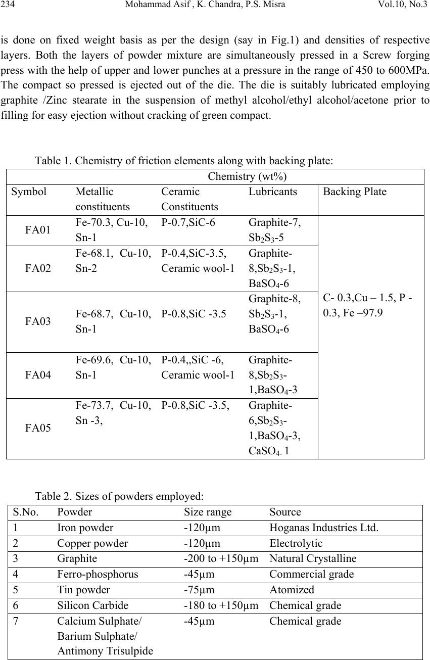 234 Mohammad Asif , K. Chandra, P.S. Misra Vol.10, No.3 is done on fixed weight basis as per the design (say in Fig.1) and densities of respective layers. Both the layers of powder mixture are simultaneously pressed in a Screw forging press with the help of upper and lower punches at a pressure in the range of 450 to 600MPa. The compact so pressed is ejected out of the die. The die is suitably lubricated employing graphite /Zinc stearate in the suspension of methyl alcohol/ethyl alcohol/acetone prior to filling for easy ejection without cracking of green compact. Table 1. Chemistry of friction elements along with backing plate: Chemistry (wt%) Symbol Metallic constituents Ceramic Constituents Lubricants Backing Plate FA01 Fe-70.3, Cu-10, Sn-1 P-0.7,SiC-6 Graphite-7, Sb2S3-5 C- 0.3,Cu – 1.5, P - 0.3, Fe –97.9 FA02 Fe-68.1, Cu-10, Sn-2 P-0.4,SiC-3.5, Ceramic wool-1 Graphite- 8,Sb2S3-1, BaSO4-6 FA03 Fe-68.7, Cu-10, Sn-1 P-0.8,SiC -3.5 Graphite-8, Sb2S3-1, BaSO4-6 FA04 Fe-69.6, Cu-10, Sn-1 P-0.4,,SiC -6, Ceramic wool-1 Graphite- 8,Sb2S3- 1,BaSO4-3 FA05 Fe-73.7, Cu-10, Sn -3, P-0.8,SiC -3.5, Graphite- 6,Sb2S3- 1,BaSO4-3, CaSO4- 1 Table 2. Sizes of powders employed: S.No. Powder Size range Source 1 Iron powder -120µm Hoganas Industries Ltd. 2 Copper powder -120µm Electrolytic 3 Graphite -200 to +150µm Natural Crystalline 4 Ferro-phosphorus -45µm Commercial grade 5 Tin powder -75µm Atomized 6 Silicon Carbide -180 to +150µm Chemical grade 7 Calcium Sulphate/ Barium Sulphate/ Antimony Trisulpide -45µm Chemical grade  Vol.10, No.3 Development of Iron Based Brake Friction Material 235 Fig.1. Die and Punch set up for Military air craft brake pad. (c) Preform coating: The green compact so produced is coated with an indigenously developed high temperature oxidation resistant ceramic coating. This is used to protect our samples from oxidation when subjected to heating. The coating is baked to remove moisture from it at a temp of 120 oC for 2 hrs in an oven. (d) Heating: The coated green compacts are heated in a furnace. The operating temperature of the furnace ranges from 1050oC for iron based brake pads, holding time 1 hr. 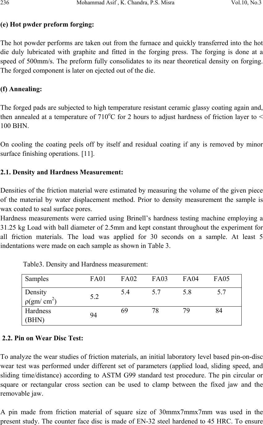 236 Mohammad Asif , K. Chandra, P.S. Misra Vol.10, No.3 (e) Hot pwder preform forging: The hot powder performs are taken out from the furnace and quickly transferred into the hot die duly lubricated with graphite and fitted in the forging press. The forging is done at a speed of 500mm/s. The preform fully consolidates to its near theoretical density on forging. The forged component is later on ejected out of the die. (f) Annealing: The forged pads are subjected to high temperature resistant ceramic glassy coating again and, then annealed at a temperature of 710oC for 2 hours to adjust hardness of friction layer to < 100 BHN. On cooling the coating peels off by itself and residual coating if any is removed by minor surface finishing operations. [11]. 2.1. Density and Hardness Measurement: Densities of the friction material were estimated by measuring the volume of the given piece of the material by water displacement method. Prior to density measurement the sample is wax coated to seal surface pores. Hardness measurements were carried using Brinell’s hardness testing machine employing a 31.25 kg Load with ball diameter of 2.5mm and kept constant throughout the experiment for all friction materials. The load was applied for 30 seconds on a sample. At least 5 indentations were made on each sample as shown in Table 3. Table3. Density and Hardness measurement: 2.2. Pin on Wear Disc Test: To analyze the wear studies of friction materials, an initial laboratory level based pin-on-disc wear test was performed under different set of parameters (applied load, sliding speed, and sliding time/distance) according to ASTM G99 standard test procedure. The pin circular or square or rectangular cross section can be used to clamp between the fixed jaw and the removable jaw. A pin made from friction material of square size of 30mmx7mmx7mm was used in the present study. The counter face disc is made of EN-32 steel hardened to 45 HRC. To ensure Samples FA01 FA02 FA03 FA04 FA05 Density ρ(gm/ cm2) 5.2 5.4 5.7 5.8 5.7 Hardness (BHN) 94 69 78 79 84  Vol.10, No.3 Development of Iron Based Brake Friction Material 237 proper contact between the test pin and the steel disc, test pin adjusting screw is provided. Normal loading on the test piece is provided by the slotted weight, which are hanged on pan. This load is transferred through the frictionless wheel to the specimen holder. Electric motor is directly connected to the steel disc and the speed of the disc can be controlled by variable regulator. It may be noted that the wear in case of GCI (Grey cast iron) is excessively high in comparison to friction materials developed in present investigation. It is justifiable since GCI does not contain wear resistant constituents in it, so we will test samples on steel disc. The pin on contact side of the disc was rubbed on polish paper of 1/0, 2/0 before clamping and counter disc is also made smooth surface finish by the polish paper of 2/0 at each cycle. The load applied is 8kg respectively. Sliding speed of 9m/s (1140 ±10 rpm at a track radius of 75mm) was kept constant for the whole experiment. Sliding time is 50 minutes. The wear loss after each cycle, the frictional force generated at every 1 minute was recorded by indigenously designed pin on disc wear testing machine. The noise generated during the wear process is also recorded by means of special microphone based noise level meter in decibels (dB). This gives an idea about the noise behavior of friction materials during the test. The density and hardness of the hot powder preform forged samples are measured; the values are given in Table 3. Measurement of rise in temperature of the wear surface as a function of time and during wear test was carried out using a thermocouple made of Chormal-Alumel wire is placed at 5mm away from the wearing surface by making hole of 2mm diameter with 3mm depth approximately. The rise in temperature is recorded till the temperature at the wear surface becomes stable. Care must be taken while brazing thermocouple bead inside the hole at friction material. Simultaneous measurement of coefficient of friction and temperature rise during the test would provide brake fading [12]. 3. RESULTS AND DISCUSSIONS Density and Hardness of Friction Materials are summarized in Table 3. Both these parameters depend on forging and annealing treatments. This also depend upon, chemistry of friction materials. The technology developed in the present investigation is capable of developing these parameters in wide ranges which is not possible in sintering technology. It is amply clear that the processing technique employed in the present investigation is superior with regard to density and hardness in comparison with the compacting and pressure sintering technology. Although hardness obtained in these brake pads are similar to the conventional brake materials, higher hardness of present materials are primarily due to higher density levels and therefore are likely to show improved performance. An initial laboratory level based pin-on-disc wear test has been performed under the parameter of applied load 8kg and the sliding speed 9m/s, as tabulated in Table 4. The noise generated during the wear process is also recorded by placing a microphone based noise level meter in decibels (dB) at a distance of 25 mm from the point of contact between friction pin and rotor disc. Rise in temperature during the wear test is also measured by placing thermocouple 5mm away from the initial wearing surface. It has been inferred that the performance of our brake pads is  238 Mohammad Asif , K. Chandra, P.S. Misra Vol.10, No.3 better than that of brake pads made by compacting and sintering technology [13]. The results of wear test are summarized in Table 4. Table 4. Pin-On-Disc Wear Test results at 8 kg Load, 9m/s Sliding speed: Area of the pin = 49mm2 samples Wear (gm) Coefficient of Friction (COF) TemperatureNoise Level, (dB) Max. Min. Avg. oCMax.Min Avg. FA01 0.63 0.38 0.35 0.365 116 38 34 36.0 FA02 0.49 0.58 0.53 0.555 168 35 32 33.5 FA03 0.61 0.39 0.38 0.385 145 30 29 29.5 FA04 0.42 0.48 0.47 0.475 169 36 30 33.0 FA05 0.64 0.46 0.45 0.455 151 32 28 30.0 Figure2 shows that the sample FA02and FA04 has the higher wear resistance than Sample FA01. FA02, and has higher coefficient of friction (COF) shown in Fig. 4, which is suitable for heavy duty applications. The range of coefficient of friction for our composites varies from about 0.16 to 0.55, which in the Aeronautical standard range except for the samples FA02 and FA04 respectively. It is noticed that the composites have better combination of solid lubricants (graphite, BaSO4, Sb2S3) with addition of SiC powder, showed better overall performance. It may be concluded that frictional characteristics can be improved with the addition of solid lubricants in bulk amount but on the other hand, its excessive amount weakens their stiffness resulting in cracks during testing. It may be inferred from the graphs that wear is within the Aeronautic standard range. In our compositions, Phosphorous (0.4-0.7) is present which develops wear resistance, but some wear resistant constituents were incorporated such as Silicon carbide. This is apparent because wear resistant materials, like silicon carbide, increase COF, then the net wear loss. The noise level during the test is not significantly altered. This is because of the fact that the noise level is related to metal content of the brake elements which in our case varies from 82% to 90%. The noise level for the samples FA03, FA05 is marginally constant; as shown in Fig 5.The temperature is also marginally increases in samples FA02 and FA04. For the friction materials developed in the present investigation, temperature rise is low due to high thermal conductivity of matrix material. The temperature rise ranges from 1010C to 168 0C. It is noticed that higher wt. % of metallic matrix improves heat transfer rate (due to higher thermal conductivity), resulting lower temperature rise.  Vol.10, No.3 Development of Iron Based Brake Friction Material 239 Fig.2. Wear (gm) for friction materials Fig.3. Temperature rise for friction materials Fig 4. Coefficient of Friction for friction material  240 Mohammad Asif , K. Chandra, P.S. Misra Vol.10, No.3 Fig.5. Noise level for friction materials 3.1. Sub Scale Dynamometer Test The test input parameters for Military transport such as AN-32 rotor aircraft applications is shown in Table 5. The required test output parameter values are shown in Table 6. The test results are tabulated in Table 7. The run down time are nearly in the specified ranges as that of output parameters (Table 6). These pads seem to be suitable for Military transport rotor aircraft applications. The test results for AN-32 aircraft for rotor application are best suitable in terms of run down time; wear in thickness, coefficient of friction. Table 5. Test input parameters: Brake pad contact area: 25.8 cm2 Applications Test Parameters Kinetic energy, kgfm Brake Speed, rpm Brake Force, kgf Heavy duty air craft Rotor 17300 1000 160 Table 6.Test output parameters: RD Time, sec COF Max. Wear for 50 cycles Min Max Min Max gm Pad thickness, mm 6 12 0.18 0.4 14 1.25  Vol.10, No.3 Development of Iron Based Brake Friction Material 241 Table 7.Test results for Heavy duty Military air craft rotor application: Sample 50 Cys. RD revl. RD time, sec. COF Mean Torque, kgfm Peak Torque, kgfm Mean Drag, kgf Peak Drag. kgf Wear Temp oC Thick.,mm Pad1 Pad2 Pad1 Pad2 FA01 Max 120 14.4 0.28 27 65 148 359 0.11 0.07 389 423 Min 96 11.6 0.22 21 43 119 240 Avg 107 12.8 0.25 24 52 133 290 FA02 Max 106 12.7 0.28 28 62 154 343 0.04 0.05 238 309 Min 94 11.2 0 0 41 0 229 Avg 101 12.1 0.28 26 51 143 282 3.2. Metallographic Analysis On the basis of detailed metallographic examination carried out and shown in Fig.6., we have observed that the microstructures of friction layer as well as backing plate are homogeneous in this hot powder preform forged sample, backing plate in this sample which is shown in Fig.6(c)., is essentially a low carbon steel but with very fine ferrite grains, and it is Widmanstattan ferrite. This is because of high speed forging employed during processing providing fast cooled fine grained structure which in turn yields high strength backing plate without resorting to higher carbon steel. It is also expected to have better toughness of backing plate due to fine ferrite grain structure which may help better engagement of brakes in actual applications. Further, friction material which is shown in Fig.6 (a) is well distributed structure. Friction layer consists of largely continuous coarse iron matrix separated by coarse graphite flakes. Yellow colored particles are clearly appearing in the friction as well as backing layer, which is probably a Copper phase. Their revelation has been highlighted by adjusting the contrast and intensity of the image and recorded pictures separately. SiC particles in friction material are embedded in the regions of graphite flake and are clearly visible like a junky particle and are recorded in microstructures [as shown in Fig.6 (a)]. The distribution of other constituents in this sample is also uniform; at interface carbon can easily diffuse towards the backing plate side leading to development of fully pearlitic structure in the adjacent backing plate. Microstructures of hot powder preform forged sample at the interface indicate strong bonding between backing plate and friction element because of enhanced diffusion of carbon from friction element side to backing plate side, and interface is clearly defined with diffusion of SiC across the interface, signifying adequate adhesion.  242 Mohammad Asif , K. Chandra, P.S. Misra Vol.10, No.3 Fig.6.(a)Friction Layer(FA05 at 100μm) (b)Interface (FA05 at 100μm) (c)Backing Layer (FA05 at 100μm) 3.3 SEM with EDAX Analysis The surface morphology of the friction material, backing plate, and interface layer are analyzed through SEM. EDAX analysis of fracture surface of different constituents present in the samples, which have been done to check homogeneity of the constituents in friction elements and backing plate as shown in Fig. 7(a) to Fig.7 (b).To identify the element wherever required was carried with the help of point/surface area analysis of EDAX analysis. QUANTA FEG 200 FEI (Netherland make) was used in the present study. 1. Elements added in the iron matrix during powder mixing are retained after powder preform forging. 2. Development of reaction/secondary phases has been arrested. 3. The fracture surfaces exhibit a ductile appearance (dimples); indicative of micro-void coalescence. 4. CONCLUSIONS 1. Hot powder preform forging (with built-in powder based backing plate) near net-shape, a process, for fabricating iron based brake pads has been successfully developed. 2. Complete elimination of H2 gas by protective high temperature oxidation resistant ceramic/glassy coating on iron based preform like paints. 3. The technology completely eliminates the problem for joining of backing plate to friction element on account of simultaneous processing. 4. Higher density levels can be achieved by hot powder pre-form forging technique. SiCParticlesCuParticles CuPart ic le s  Vol.10, No.3 Development of Iron Based Brake Friction Material 243 (a)Friction layer (FA05) 100μm (b)Interface (FA05) 100μm (c)Backing plate (FA05) 100μm Figure 7(a-c).SEM and EDAX of Fracture surface of hot powder preform forged brake pad. ACKNOWLEDGEMENT Authors are highly thankful to Foundry and Forge Division, HAL Bangalore, India for providing testing facilities to test our samples on their sub-scale dynamometer. REFERENCES [1]. Czichos H., Molgaard J., “Towards a general theory of tribological systems”,  244 Mohammad Asif , K. Chandra, P.S. Misra Vol.10, No.3 Wear,14, 1977, pp. 247-264. [2]. Lazarev G.E., 1971, “Evaluation of wear resistance of friction materials”, Powder Metallurgy and Metal Ceramics, 7, No. 10, pp 903-905. [3]. Garbar II., 1997, Wear, “The effect of load on the structure and wear of friction pair materials”., vol 5, pp205:240. [4]. Tu JP, et al. Friction and wear behavior of Cu–Fe3Al powder metallurgical composites in dry sliding., 1998 ,Wear; vol 9, pp220-272. [5]. Tyler.G.Hicks, ‘Handbook of mechanical engineering calculations-II edition’, ISBN 0071458867, 2006, McGraw-hill publications. [6]. Dixon R.H.T., Clayton A., ‘Powder Metallurgy for engineers’, Machinery Publishing Co. Ltd. London., 1971, pp166-183. [7]. Shvedkov E.L., Derkacheva G.M., Panaioti I., ‘Optimization of the manufacture of a sintered iron-phosphorus base frictional material’, Powder metallurgy and metal ceramics vol. 14, No. 4, 1975, pp304-307. [8]. Prochazka V., Navara E., Miskovic V., Kosta K., ‘The influence of copper on the properties of sintered iron-graphite friction materials’, published in ‘Perspective in Powder Metallurgy: Friction and Antifriction Materials –Vol. 4’, edited by Hausner Henery H., Roll Kempton H., Johnson Peter K. Plenum Press, New York, London. 1970, pp123-127. [9]. Dutta D., Mohan G., Chatterjee B., Krishnadas Nair C.G., ‘Development of sintered metalloceramic friction material for the wheel brakes of a military transport aircraft’, Published in, ‘Composites: Science and Technology (ISBN 81-224-1251-3)’ edited by R.C. Prasad, P. Ramakrishan, New Age International (P) Ltd., New Delhi., 2002, pp 94- 114. [10]. Kryachek, V. M., Jan., 2005, ‘Friction composites: Traditions & new solutions (review). parts2. Composites’, Powder Metallurgy & Metal Ceramics, Vol. 44, pp05-16. [11]. Misra P. S., Chandra K. “Development of High Temperature Oxidations Resistant Glassy Coating” Indian Patent, application No. 153/DEL/2010 dated Jan. 27, 2010. [12]. Chaturvedi A. K., Chandra K., Misra P. S. October 2009, Journal of Tribology, “Wear Characterization of Al/Ingredients MMFC” vol. 131 / 041601-1. [13]. Asif M., Chandra K., Misra P. S., 2010, “Tribological studies of iron-based brake pads made by P/M route used for heavy duty applications” submitted and presented in International conference organised by PMAI, Jaipur, India (held Jan.28-30, 2010). published in transaction of PMAI, Vol. 36, 2010, pp78-81. |